2007 ISUZU KB P190 engine
[x] Cancel search: enginePage 1970 of 6020
ENGINE CONTROL SYSTEM (4JK1/4JJ1) 6E-353
Description and Operation
Engine Control Module (ECM) Description
Engine Control Module (ECM) Service Precautions
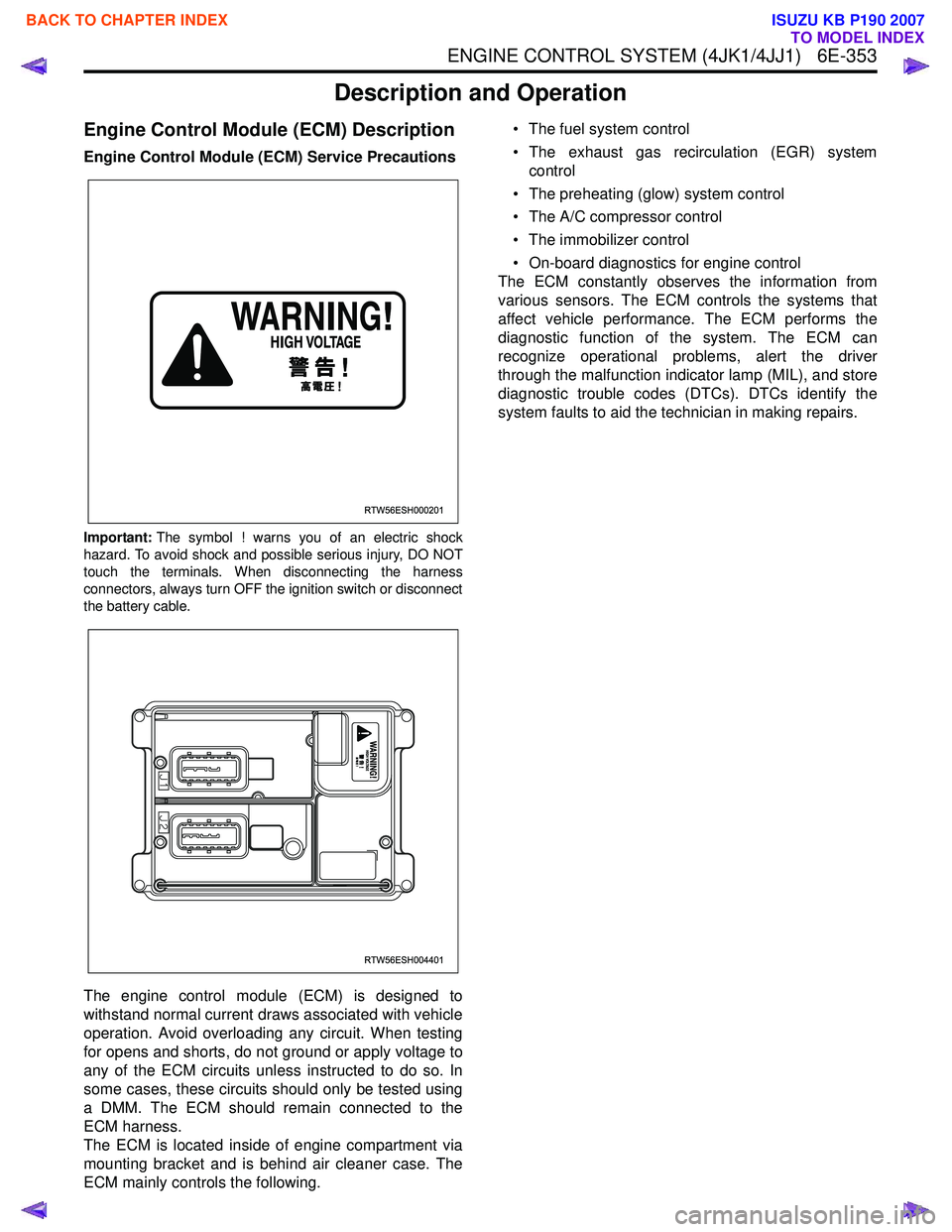
Important:The symbol ! warns you of an electric shock
hazard. To avoid shock and possible serious injury, DO NOT
touch the terminals. When disconnecting the harness
connectors, always turn OFF the ignition switch or disconnect
the battery cable.
The engine control module (ECM) is designed to
withstand normal current draws associated with vehicle
operation. Avoid overloading any circuit. When testing
for opens and shorts, do not ground or apply voltage to
any of the ECM circuits unless instructed to do so. In
some cases, these circuits should only be tested using
a DMM. The ECM should remain connected to the
ECM harness.
The ECM is located inside of engine compartment via
mounting bracket and is behind air cleaner case. The
ECM mainly controls the following. • The fuel system control
• The exhaust gas recirculation (EGR) system control
• The preheating (glow) system control
• The A/C compressor control
• The immobilizer control
• On-board diagnostics for engine control
The ECM constantly observes the information from
various sensors. The ECM controls the systems that
affect vehicle performance. The ECM performs the
diagnostic function of the system. The ECM can
recognize operational problems, alert the driver
through the malfunction indicator lamp (MIL), and store
diagnostic trouble codes (DTCs). DTCs identify the
system faults to aid the technician in making repairs.
RTW56ESH000201
RTW56ESH004401
BACK TO CHAPTER INDEX
TO MODEL INDEX
ISUZU KB P190 2007
Page 1971 of 6020
6E-354 ENGINE CONTROL SYSTEM (4JK1/4JJ1)
ECM Input & Output
ECM Voltage Description
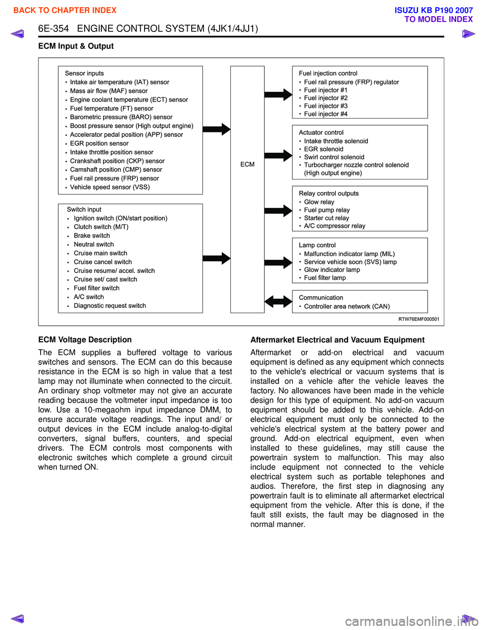
The ECM supplies a buffered voltage to various
switches and sensors. The ECM can do this because
resistance in the ECM is so high in value that a test
lamp may not illuminate when connected to the circuit.
An ordinary shop voltmeter may not give an accurate
reading because the voltmeter input impedance is too
low. Use a 10-megaohm input impedance DMM, to
ensure accurate voltage readings. The input and/ or
output devices in the ECM include analog-to-digital
converters, signal buffers, counters, and special
drivers. The ECM controls most components with
electronic switches which complete a ground circuit
when turned ON. Aftermarket Electrical and Vacuum Equipment
Aftermarket or add-on electrical and vacuum
equipment is defined as any equipment which connects
to the vehicle's electrical or vacuum systems that is
installed on a vehicle after the vehicle leaves the
factory. No allowances have been made in the vehicle
design for this type of equipment. No add-on vacuum
equipment should be added to this vehicle. Add-on
electrical equipment must only be connected to the
vehicle's electrical system at the battery power and
ground. Add-on electrical equipment, even when
installed to these guidelines, may still cause the
powertrain system to malfunction. This may also
include equipment not connected to the vehicle
electrical system such as portable telephones and
audios. Therefore, the first step in diagnosing any
powertrain fault is to eliminate all aftermarket electrical
equipment from the vehicle. After this is done, if the
fault still exists, the fault may be diagnosed in the
normal manner.
RTW76EMF000501
Sensor inputs
· Intake air temperature (IAT) sensor
· Mass air flow (MAF) sensor
· Engine coolant temperature (ECT) sensor
· Fuel temperature (FT) sensor
· Barometric pressure (BARO) sensor
· Boost pressure sensor (High output engine)
· Accelerator pedal position (APP) sensor
· EGR position sensor
· Intake throttle position sensor
· Crankshaft position (CKP) sensor
· Camshaft position (CMP) sensor
· Fuel rail pressure (FRP) sensor
· Vehicle speed sensor (VSS)
Switch input
· Ignition switch (ON/start position)
· Clutch switch (M/T)
· Brake switch
· Neutral switch
· Cruise main switch
· Cruise cancel switch
· Cruise resume/ accel. switch
· Cruise set/ cast switch
· Fuel filter switch
· A/C switch
· Diagnostic request switch
Fuel injection control
· Fuel rail pressure (FRP) regulator
· Fuel injector #1
· Fuel injector #2
· Fuel injector #3
· Fuel injector #4
Relay control outputs
· Glow relay
· Fuel pump relay
· Starter cut relay
· A/C compressor relay
Lamp control
· Malfunction indicator lamp (MIL)
· Service vehicle soon (SVS) lamp
· Glow indicator lamp
· Fuel filter lamp
Communication
· Controller area network (CAN)
Actuator control
· Intake throttle solenoid
· EGR solenoid
· Swirl control solenoid
· Turbocharger nozzle control solenoid
(High output engine)ECM
BACK TO CHAPTER INDEX
TO MODEL INDEX
ISUZU KB P190 2007
Page 1972 of 6020
ENGINE CONTROL SYSTEM (4JK1/4JJ1) 6E-355
Electrostatic Discharge Damage
Electronic components used in the ECM are often
designed to carry very low voltage. Electronic
components are susceptible to damage caused by
electrostatic discharge. By comparison, as much as
4,000 volts may be needed for a person to feel even
the zap of a static discharge. There are several ways
for a person to become statically charged. The most
common methods of charging are by friction and
induction.
• An example of charging by friction is a person sliding across a vehicle seat.
Important: To prevent possible electrostatic discharge
damage, follow these guidelines:
• Do not touch the ECM connector pins or soldered components on the ECM circuit board.
• Do not open the replacement part package until the part is ready to be installed.
• Before removing the part from the package, ground the package to a known good ground on
the vehicle.
• If the part has been handled while sliding across the seat, while sitting down from a standing
position, or while walking a distance, touch a
known good ground before installing the part.
• Charge by induction occurs when a person with well insulated shoes stands near a highly charged
object and momentarily touches ground. Charges
of the same polarity are drained off leaving the
person highly charged with opposite polarity.
Malfunction Indicator Lamp (MIL) Operation
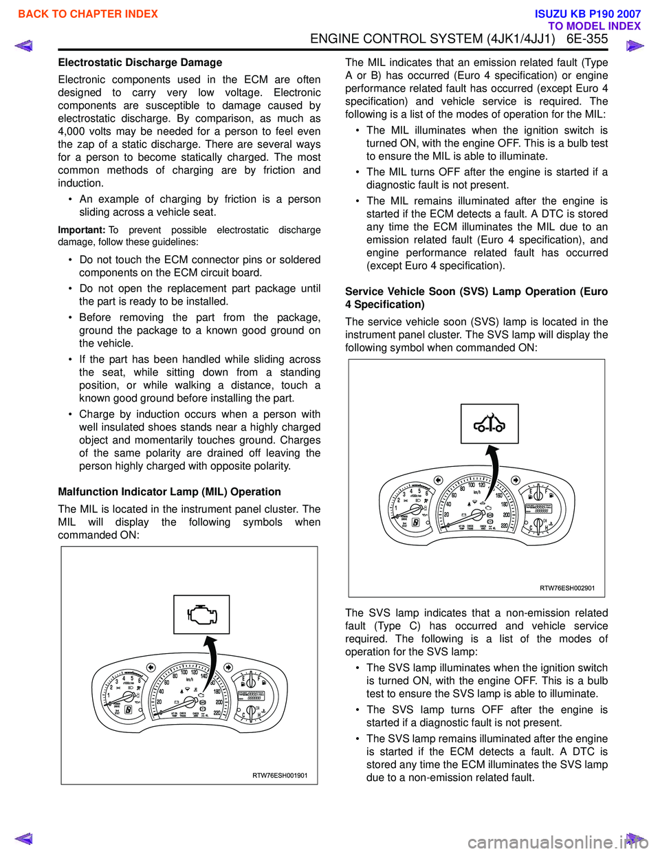
The MIL is located in the instrument panel cluster. The
MIL will display the following symbols when
commanded ON: The MIL indicates that an emission related fault (Type
A or B) has occurred (Euro 4 specification) or engine
performance related fault has occurred (except Euro 4
specification) and vehicle service is required. The
following is a list of the modes of operation for the MIL:
• The MIL illuminates when the ignition switch is turned ON, with the engine OFF. This is a bulb test
to ensure the MIL is able to illuminate.
• The MIL turns OFF after the engine is started if a diagnostic fault is not present.
• The MIL remains illuminated after the engine is started if the ECM detects a fault. A DTC is stored
any time the ECM illuminates the MIL due to an
emission related fault (Euro 4 specification), and
engine performance related fault has occurred
(except Euro 4 specification).
Service Vehicle Soon (SVS) Lamp Operation (Euro
4 Specification)
The service vehicle soon (SVS) lamp is located in the
instrument panel cluster. The SVS lamp will display the
following symbol when commanded ON:
The SVS lamp indicates that a non-emission related
fault (Type C) has occurred and vehicle service
required. The following is a list of the modes of
operation for the SVS lamp:
• The SVS lamp illuminates when the ignition switch is turned ON, with the engine OFF. This is a bulb
test to ensure the SVS lamp is able to illuminate.
• The SVS lamp turns OFF after the engine is started if a diagnostic fault is not present.
• The SVS lamp remains illuminated after the engine is started if the ECM detects a fault. A DTC is
stored any time the ECM illuminates the SVS lamp
due to a non-emission related fault.
RTW76ESH001901
RTW76ESH002901
BACK TO CHAPTER INDEX
TO MODEL INDEX
ISUZU KB P190 2007
Page 1973 of 6020
6E-356 ENGINE CONTROL SYSTEM (4JK1/4JJ1)
Engine Control Component Description
Accelerator Pedal Position (APP) Sensor
Legend1. Accelerator pedal position (APP) sensor
2. Accelerator pedal bracket
3. Nut
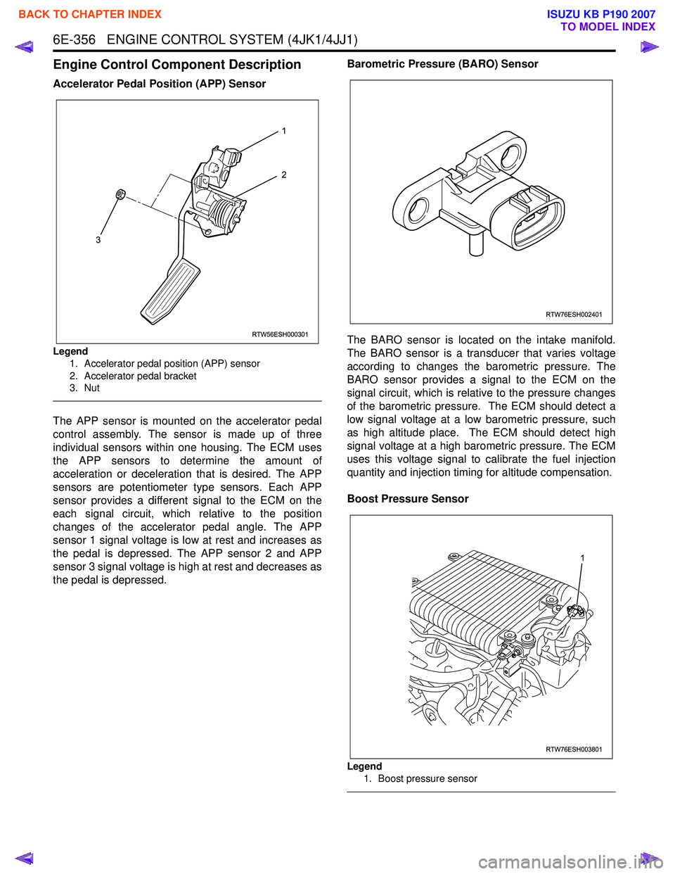
The APP sensor is mounted on the accelerator pedal
control assembly. The sensor is made up of three
individual sensors within one housing. The ECM uses
the APP sensors to determine the amount of
acceleration or deceleration that is desired. The APP
sensors are potentiometer type sensors. Each APP
sensor provides a different signal to the ECM on the
each signal circuit, which relative to the position
changes of the accelerator pedal angle. The APP
sensor 1 signal voltage is low at rest and increases as
the pedal is depressed. The APP sensor 2 and APP
sensor 3 signal voltage is high at rest and decreases as
the pedal is depressed. Barometric Pressure (BARO) Sensor
The BARO sensor is located on the intake manifold.
The BARO sensor is a transducer that varies voltage
according to changes the barometric pressure. The
BARO sensor provides a signal to the ECM on the
signal circuit, which is relative to the pressure changes
of the barometric pressure. The ECM should detect a
low signal voltage at a low barometric pressure, such
as high altitude place. The ECM should detect high
signal voltage at a high barometric pressure. The ECM
uses this voltage signal to calibrate the fuel injection
quantity and injection timing for altitude compensation.
Boost Pressure Sensor
Legend 1. Boost pressure sensor
RTW56ESH000301
1
2
3
RTW76ESH002401
RTW76ESH003801
1
BACK TO CHAPTER INDEX
TO MODEL INDEX
ISUZU KB P190 2007
Page 1974 of 6020
ENGINE CONTROL SYSTEM (4JK1/4JJ1) 6E-357
The boost pressure sensor is located in the air
induction tubing. The boost pressure sensor is a
transducer that varies voltage according to changes in
the air pressure inside the air tubing. The boost
pressure sensor provides a signal to the ECM on the
signal circuit, which is relative to the pressure changes
in the air tubing. The ECM should detect a low signal
voltage at a low boost pressure, such as low engine
load. The ECM should detect high signal voltage at a
high boost pressure, such as high engine load.
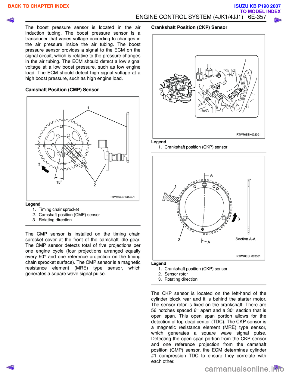
Camshaft Position (CMP) Sensor
Legend 1. Timing chair sprocket
2. Camshaft position (CMP) sensor
3. Rotating direction
The CMP sensor is installed on the timing chain
sprocket cover at the front of the camshaft idle gear.
The CMP sensor detects total of five projections per
one engine cycle (four projections arranged equally
every 90 ° and one reference projection on the timing
chain sprocket surface). The CMP sensor is a magnetic
resistance element (MRE) type sensor, which
generates a square wave signal pulse. Crankshaft Position (CKP) Sensor
Legend
1. Crankshaft position (CKP) sensor
Legend
1. Crankshaft position (CKP) sensor
2. Sensor rotor
3. Rotating direction
The CKP sensor is located on the left-hand of the
cylinder block rear and it is behind the starter motor.
The sensor rotor is fixed on the crankshaft. There are
56 notches spaced 6 ° apart and a 30 ° section that is
open span. This open span portion allows for the
detection of top dead center (TDC). The CKP sensor is
a magnetic resistance element (MRE) type sensor,
which generates a square wave signal pulse.
Detecting the open span portion from the CKP sensor
and one reference projection from the camshaft
position (CMP) sensor, the ECM determines cylinder
#1 compression TDC to ensure they correlate with
each other.
RTW56ESH000401
1
3 2
15
RTW76ESH002301
1
RTW76ESH003301
A
A Section A-A
1
2 3
BACK TO CHAPTER INDEX
TO MODEL INDEX
ISUZU KB P190 2007
Page 1975 of 6020
6E-358 ENGINE CONTROL SYSTEM (4JK1/4JJ1)
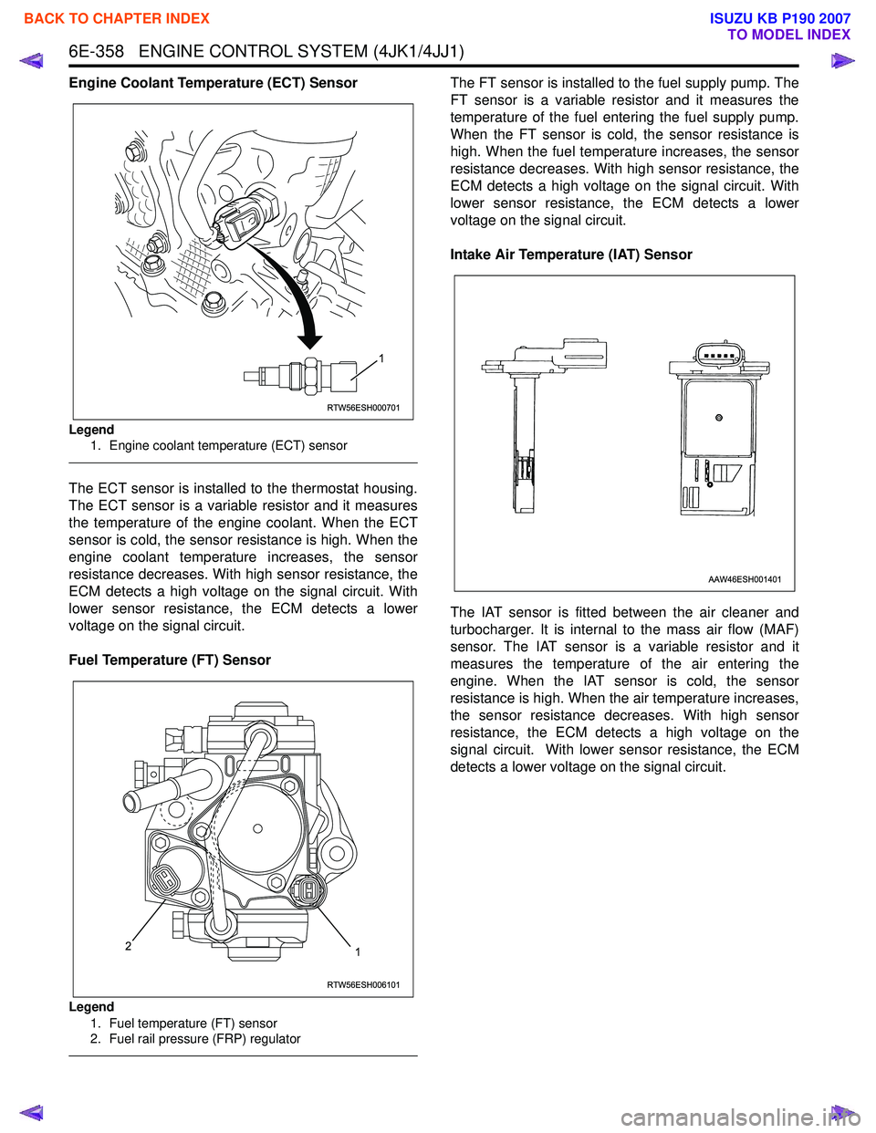
Engine Coolant Temperature (ECT) Sensor
Legend1. Engine coolant temperature (ECT) sensor
The ECT sensor is installed to the thermostat housing.
The ECT sensor is a variable resistor and it measures
the temperature of the engine coolant. When the ECT
sensor is cold, the sensor resistance is high. When the
engine coolant temperature increases, the sensor
resistance decreases. With high sensor resistance, the
ECM detects a high voltage on the signal circuit. With
lower sensor resistance, the ECM detects a lower
voltage on the signal circuit.
Fuel Temperature (FT) Sensor
Legend 1. Fuel temperature (FT) sensor
2. Fuel rail pressure (FRP) regulator
The FT sensor is installed to the fuel supply pump. The
FT sensor is a variable resistor and it measures the
temperature of the fuel entering the fuel supply pump.
When the FT sensor is cold, the sensor resistance is
high. When the fuel temperature increases, the sensor
resistance decreases. With high sensor resistance, the
ECM detects a high voltage on the signal circuit. With
lower sensor resistance, the ECM detects a lower
voltage on the signal circuit.
Intake Air Temperature (IAT) Sensor
The IAT sensor is fitted between the air cleaner and
turbocharger. It is internal to the mass air flow (MAF)
sensor. The IAT sensor is a variable resistor and it
measures the temperature of the air entering the
engine. When the IAT sensor is cold, the sensor
resistance is high. When the air temperature increases,
the sensor resistance decreases. With high sensor
resistance, the ECM detects a high voltage on the
signal circuit. With lower sensor resistance, the ECM
detects a lower voltage on the signal circuit.
RTW56ESH000701
1
RTW56ESH006101
12
AAW46ESH001401
BACK TO CHAPTER INDEX
TO MODEL INDEX
ISUZU KB P190 2007
Page 1976 of 6020
ENGINE CONTROL SYSTEM (4JK1/4JJ1) 6E-359
Mass Air Flow (MAF) SensorThe MAF sensor is an air flow meter that measures the
amount of air that enters the engine. It is fitted between
the air cleaner and turbocharger. A small quantity of air
that enters the engine indicates deceleration or idle
speed. A large quantity of air that enters the engine
indicates acceleration or a high load condition. The
MAF sensor assembly consists of a MAF sensor
element and an intake air temperature (IAT) sensor that
are both exposed to the air flow to be measured. The
MAF sensor element measures the partial air mass
through a measurement duct on the sensor housing.
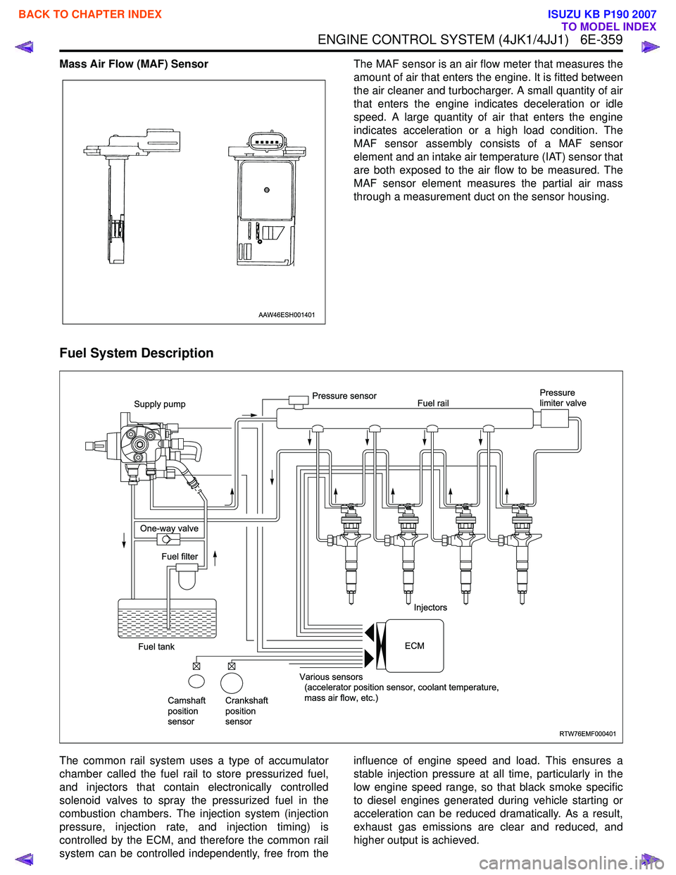
Fuel System Description
The common rail system uses a type of accumulator
chamber called the fuel rail to store pressurized fuel,
and injectors that contain electronically controlled
solenoid valves to spray the pressurized fuel in the
combustion chambers. The injection system (injection
pressure, injection rate, and injection timing) is
controlled by the ECM, and therefore the common rail
system can be controlled independently, free from the influence of engine speed and load. This ensures a
stable injection pressure at all time, particularly in the
low engine speed range, so that black smoke specific
to diesel engines generated during vehicle starting or
acceleration can be reduced dramatically. As a result,
exhaust gas emissions are clear and reduced, and
higher output is achieved.
AAW46ESH001401
RTW76EMF000401
Supply pump
One-way valve
Fuel tank Fuel filter
Camshaft
position
sensor Crankshaft
position
sensor Various sensors
(accelerator position sensor, coolant temperature,
mass air flow, etc.) Injectors
Pressure sensor
Fuel rail Pressure
limiter valve
ECM
BACK TO CHAPTER INDEX
TO MODEL INDEX
ISUZU KB P190 2007
Page 1977 of 6020
6E-360 ENGINE CONTROL SYSTEM (4JK1/4JJ1)
1. High Pressure Control• Enables high pressure injection from low engine speed range.
• Optimizes control to minimize particulate matter and NOx emissions.
2. Injection Timing Control
• Enables finely tuned optimized control in accordance with running conditions.
3. Injection Rate Control
• Pilot injection control that performs a small amount of injection before main injection.
The fuel rail system consists primarily of a fuel supply
pump, fuel rail, injectors, and ECM.
Fuel System Component Description
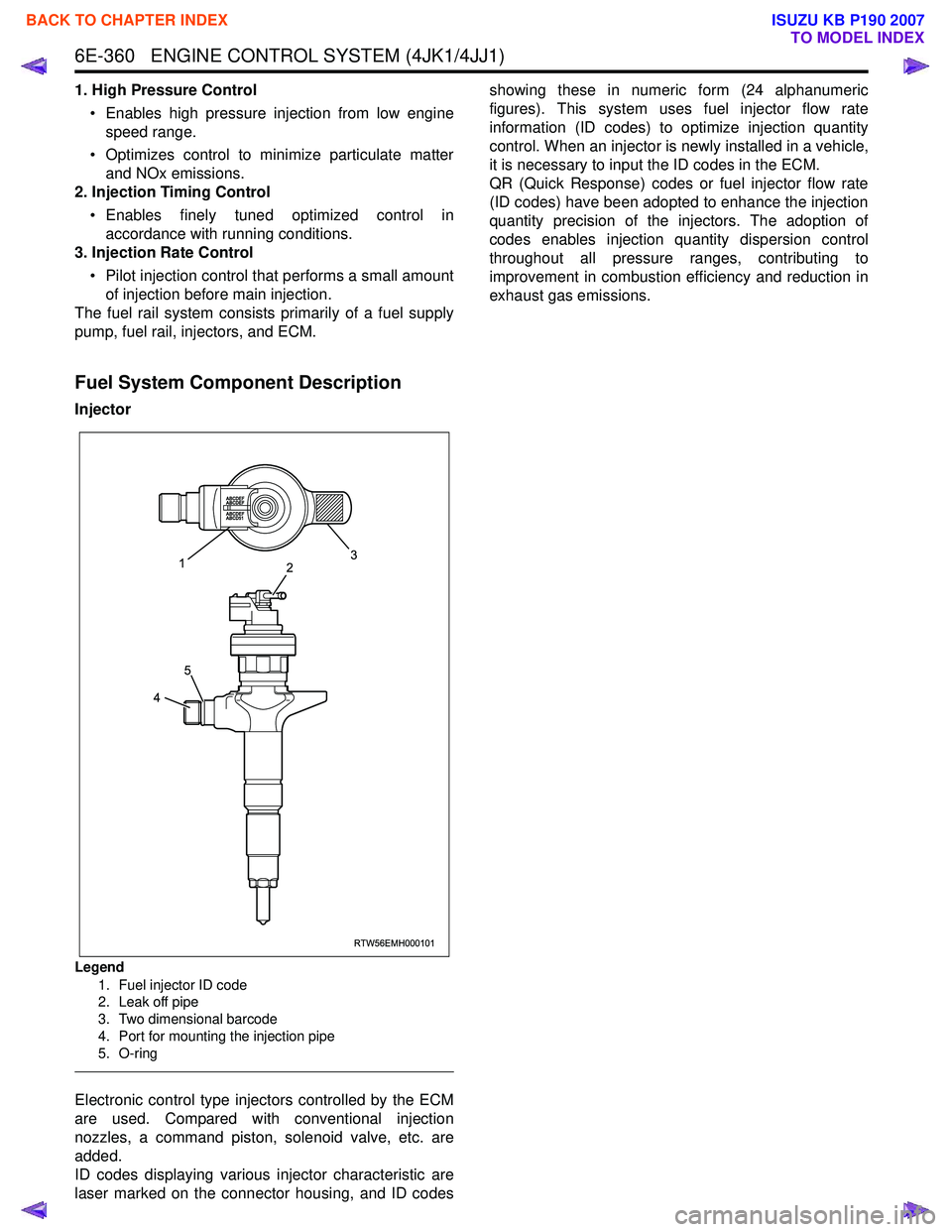
Injector
Legend
1. Fuel injector ID code
2. Leak off pipe
3. Two dimensional barcode
4. Port for mounting the injection pipe
5. O-ring
Electronic control type injectors controlled by the ECM
are used. Compared with conventional injection
nozzles, a command piston, solenoid valve, etc. are
added.
ID codes displaying various injector characteristic are
laser marked on the connector housing, and ID codes showing these in numeric form (24 alphanumeric
figures). This system uses fuel injector flow rate
information (ID codes) to optimize injection quantity
control. When an injector is newly installed in a vehicle,
it is necessary to input the ID codes in the ECM.
QR (Quick Response) codes or fuel injector flow rate
(ID codes) have been adopted to enhance the injection
quantity precision of the injectors. The adoption of
codes enables injection quantity dispersion control
throughout all pressure ranges, contributing to
improvement in combustion efficiency and reduction in
exhaust gas emissions.
RTW56EMH000101
23
1
4
5
BACK TO CHAPTER INDEX
TO MODEL INDEX
ISUZU KB P190 2007