Page 1994 of 6020
EXHAUST SYSTEM (4JK1/4JJ1) 6F-9
Removal
1. Drain the coolant.
2. Remove the intercooler.
3. Remove the heat protector.
4. Disconnect the water hoses from the EGR coole
r
water pipes.
5. Remove the EGR cooler.
Installation (Standard Output)
1. Gasket
2. EGR Cooler
3. Nuts and Bolts
RTW 56FSH000201
• Temporary tightening order
1 – 2 – 4 – 5 - 3
• Fully tightening order
4 – 5 – 1 – 2 - 3
Tighten the nuts and bolts to the specified torque.
Tightening torque: 27 N ⋅
⋅⋅
⋅
m (2.8 kg ⋅
⋅⋅
⋅
m / 20 lb ft)
4. W ater hose
5. Heat protector • Tighten the bolts to the specified torque.
Tightening torque: 10 N ⋅
⋅⋅
⋅
m (1.0 kg ⋅
⋅⋅
⋅
m / 87 lb in)
RTW 56ASH014601
6. Replenish the engine coolant.
BACK TO CHAPTER INDEX
TO MODEL INDEX
ISUZU KB P190 2007
Page 1995 of 6020
6F-10 EXHAUST SYSTEM (4JK1/4JJ1)
Installation (High Output)
1. Gasket
2. EGR Cooler
3. Nuts and Bolts
6
543
1
2
RTW 76FSH000201
• Temporary tightening order
1 →2→ 3→ 4→ 5→ 6
• Fully tightening order
3 →4→ 5→ 1→ 2→ 6
Tighten the nuts and bolts to the specified torque.
Tightening torque: Nuts and bolts 1-5: 27 N ⋅
⋅⋅
⋅
m (2.8 kg ⋅
⋅⋅
⋅
m / 20 lb ft)
Bolt 6: 52 N⋅
⋅⋅
⋅
m (5.3 kg ⋅
⋅⋅
⋅
m / 38 lb ft)
4. W ater hose
5. Heat protector • Tighten the bolts to the specified torque.
Tightening torque: 25 N ⋅
⋅⋅
⋅
m (2.5 kg ⋅
⋅⋅
⋅
m / 18 lb ft)
RTW 76FSH000101
6. Replenish the engine coolant.
BACK TO CHAPTER INDEX
TO MODEL INDEX
ISUZU KB P190 2007
Page 1998 of 6020
ENGINE SPEED CONTROL SYSTEM (4JK1/4JJ1) 6H-1
SECTION 6H
ENGINE SPEED CONTROL SYSTEM
CONTENTS
Accelerator Pedal Position (APP) Sensor ......... 6H-2
Removal .......................................................... 6H-2
Installation ....................................................... 6H-2
How to adjust for APP Sensor......................... 6H-2
BACK TO CHAPTER INDEX
TO MODEL INDEX
ISUZU KB P190 2007
Page 1999 of 6020
6H-2 ENGINE SPEED CONTROL SYSTEM (4JK1/4JJ1)
Accelerator Pedal Position (APP) Sensor
Removal
1. Turn OFF the ignition.
2. Disconnect the APP sensor harness connector.
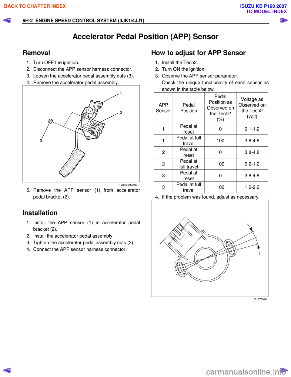
3. Loosen the accelerator pedal assembly nuts (3).
4. Remove the accelerator pedal assembly.
RTW 56ESH000301
5. Remove the APP sensor (1) from accelerator
pedal bracket (2).
Installation
1. Install the APP sensor (1) in accelerator pedal
bracket (2).
2. Install the accelerator pedal assembly.
3. Tighten the accelerator pedal assembly nuts (3).
4. Connect the APP sensor harness connector.
How to adjust for APP Sensor
1. Install the Tech2.
2. Turn ON the ignition.
3. Observe the APP sensor parameter.
Check the unique functionality of each sensor as shown in the table below.
APP
Sensor Pedal
Position Pedal
Position as
Observed on the Tech2 (%) Voltage as
Observed on the Tech2 (volt)
1 Pedal at
reset 0 0.1-1.2
1 Pedal at full
travel 100 3.8-4.8
2 Pedal at
reset 0 3.8-4.8
2 Pedal at
full travel 100 0.2-1.2
3 Pedal at
reset 0 3.8-4.8
3 Pedal at full
travel 100 1.2-2.2
4. If the problem was found, adjust as necessary.
101RY00011
BACK TO CHAPTER INDEX
TO MODEL INDEX
ISUZU KB P190 2007
Page 2000 of 6020
Section 6 Engine Diagnosis .......................................................................................... 2001 PAGE
Section 6A Engine Mechanical .................................................................................... 2015
Section 6B Engine Cooling .......................................................................................... 2105
Section 6C Fuel System .......................................................................... ..................... 2119
Section 6D Engine Electrical ....................................................................................... 2137
Section 6E Engine Driveability and Emissions .......................................................... 2171
Section 6F Exhaust System ........................................................................................ 2450
SECTION 6
ENGINE
TA BLE OF CONTENTS
C24SE MODEL
EN G IN E (C 24SE) 6
Section 6 G En gine L ubri ca tio n.................................................................................... 24 65
Section 6H Engine Speed Control System ................................................................ 2472
Section 6J Induction ................................................................................................... 2476
BACK TO CHAPTER INDEX
TO MODEL INDEX
ISUZU KB P190 2007
Page 2001 of 6020
ENGINE DIAGNOSIS (C24SE) 6-1
SECTION 6
ENGINE DIAGNOSIS
TABLE OF CONTENTS
PAGE
Engine Diagnosis .............................................................................................................. 6- 2
Hard Starting ................................................................................................................. 6- 2
Engine Compression Test Procedure ......................................................................... 6- 3
Rough Engine Idling or Engine Stalling...................................................................... 6- 4
Rough Engine Running ................................................................................................ 6- 5
Hesitation ..................................................................................................................... . 6- 6
Engine Lacks Power ..................................................................................................... 6- 7
Engine Noisy ................................................................................................................. 6 - 8
Abnormal Noise Due to Hydraulic Lash Adjustor ...................................................... 6- 9
Troubleshooting Procedure ......................................................................................... 6- 9
Abnormal Combustion ................................................................................................. 6-11
Engine Oil Consumption Excessive............................................................................ 6-12
Fuel Consumption Excessive ...................................................................................... 6-13
Oil Problems.................................................................................................................. 6-13
Engine Oil Pressure Check .......................................................................................... 6-13
Malfunction Indicator Lamp ......................................................................................... 6-14
BACK TO CHAPTER INDEX
TO MODEL INDEX
ISUZU KB P190 2007
Page 2002 of 6020
6-2 ENGINE DIAGNOSIS (C24SE)
Engine Diagnosis
Hard Starting
1.Starting Motor Does Not Turn Over
Trouble Shooting Procedure
Turn on headlights and starter switch.
Condition Possible cause Correction
Headlights go out or dim
considerably Battery run down or under
charged Recharge or replace battery
Terminals poorly connected Clean battery posts and terminals
and connect properly
Starting motor coil circuit shorted Overhaul or replace
Starting motor defective Overhaul or replace
2.Ignition Trouble - Starting Motor Turns Over But Engine Does Not Start
Spark Test Disconnect a high tension cable from any spark plug.
Connect the spark plug tester (use commercially
available tool), crank the engine, and check if a spark is
generated in the spark plug tester. Before cranking the
engine, make sure that the spark plug tester is properly
grounded. To avoid electrical shock, do not touch the
high tension cable while the engine is running.
Condition Possible cause Correction
Spark jumps across gap Spark plug defective Clean, adjust spark gap or replace
Spark plug wire in correct Connect properly or replace
Ignition timing incorrect Refer to Ignition System
Fuel not reaching fuel injector(s)
or engine Refer to item 3 (Trouble in fuel
system)
Valve timing incorrect Adjust
Engine lacks compression Refer to item 4 (Engine lacks
compression)
No sparking takes place Ignition coil disconnected or
broken Connect properly or replace
Electronic Ignition System with
module Replace
Poor connections in engine
harness Correct
Engine Control Module cable
disconnected or defective Correct or replace
BACK TO CHAPTER INDEX
TO MODEL INDEX
ISUZU KB P190 2007
Page 2003 of 6020
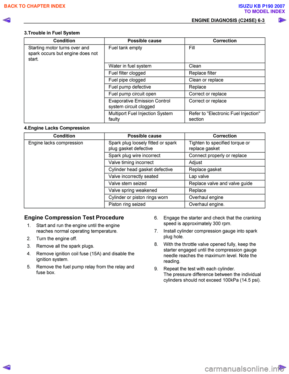
ENGINE DIAGNOSIS (C24SE) 6-3
3.Trouble in Fuel System Condition Possible cause Correction
Starting motor turns over and
spark occurs but engine does not
start. Fuel tank empty Fill
Water in fuel system Clean
Fuel filter clogged Replace filter
Fuel pipe clogged Clean or replace
Fuel pump defective Replace
Fuel pump circuit open Correct or replace
Evaporative Emission Control
system circuit clogged Correct or replace
Multiport Fuel Injection System
faulty Refer to "Electronic Fuel Injection"
section
4.Engine Lacks Compression
Condition Possible cause Correction
Engine lacks compression Spark plug loosely fitted or spark
plug gasket defective Tighten to specified torque or
replace gasket
Spark plug wire incorrect Connect properly or replace
Valve timing incorrect Adjust
Cylinder head gasket defective Replace gasket
Valve incorrectly seated Lap valve
Valve stem seized Replace valve and valve guide
Valve spring weakened Replace
Cylinder or piston rings worn Overhaul engine
Piston ring seized Overhaul engine.
Engine Compression Test Procedure
1. Start and run the engine until the engine
reaches normal operating temperature.
2. Turn the engine off.
3. Remove all the spark plugs.
4. Remove ignition coil fuse (15A) and disable the ignition system.
5. Remove the fuel pump relay from the relay and fuse box. 6. Engage the starter and check that the cranking
speed is approximately 300 rpm.
7. Install cylinder compression gauge into spark plug hole.
8. With the throttle valve opened fully, keep the starter engaged until the compression gauge
needle reaches the maximum level. Note the
reading.
9. Repeat the test with each cylinder. The pressure difference between the individual
cylinders should not exceed 100kPa (14.5 psi).
BACK TO CHAPTER INDEX
TO MODEL INDEX
ISUZU KB P190 2007