2007 ISUZU KB P190 cooling
[x] Cancel search: coolingPage 1541 of 6020
6B-18 ENGINE COOLING (4JK1/4JJ1)
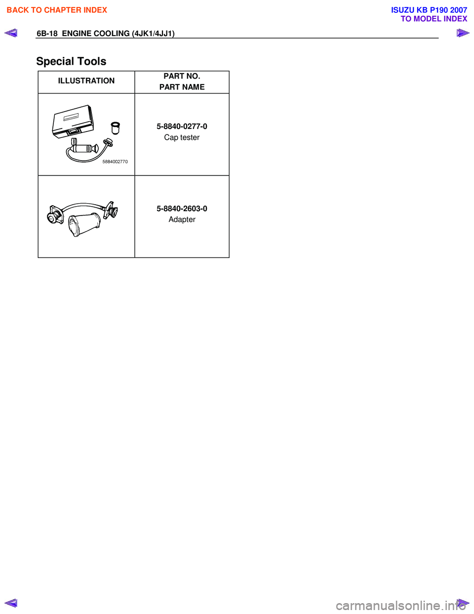
Special Tools
ILLUSTRATION PART NO.
PART NAME
5-8840-0277-0
Cap tester
5-8840-2603-0
Adapter
BACK TO CHAPTER INDEX
TO MODEL INDEX
ISUZU KB P190 2007
Page 1569 of 6020
6C-28 FUEL SYSTEM (4JK1/4JJ1)
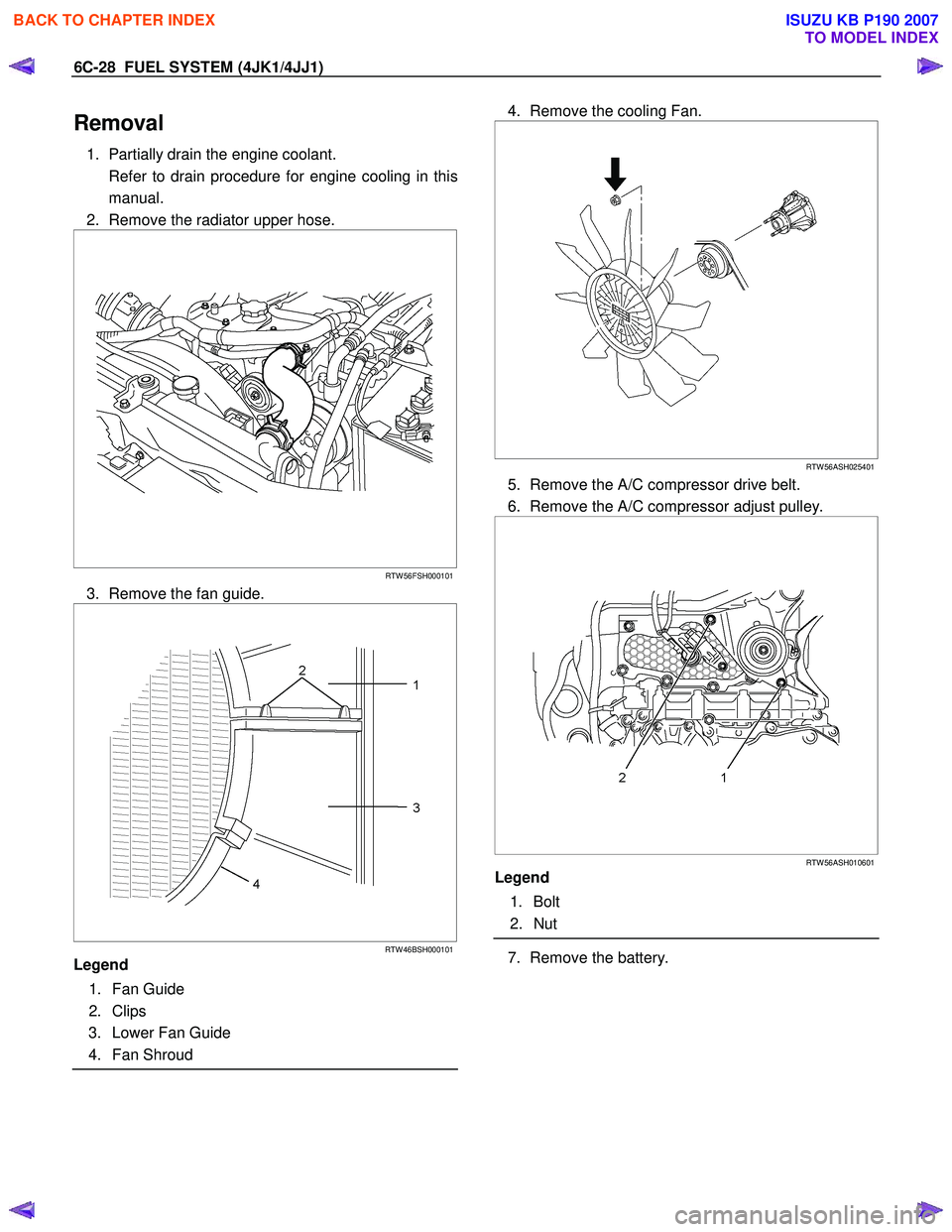
Removal
1. Partially drain the engine coolant.
Refer to drain procedure for engine cooling in this manual.
2. Remove the radiator upper hose.
RTW 56FSH000101
3. Remove the fan guide.
RTW 46BSH000101
Legend
1. Fan Guide
2. Clips
3. Lower Fan Guide
4. Fan Shroud
4. Remove the cooling Fan.
RTW 56ASH025401
5. Remove the A/C compressor drive belt.
6. Remove the A/C compressor adjust pulley.
RTW 56ASH010601
Legend
1. Bolt
2. Nut
7. Remove the battery.
BACK TO CHAPTER INDEX
TO MODEL INDEX
ISUZU KB P190 2007
Page 1578 of 6020

FUEL SYSTEM (4JK1/4JJ1) 6C-37
24. Install the A/C compressor.
RTW 56ASH004201
Legend
1. A/C Compressor Bracket
2. Intake Duct
3. A/C Compressor
Tighten the bolts to the specified torque.
Tightening torque: 44 N ⋅
⋅⋅
⋅
m (4.5 kg ⋅
⋅⋅
⋅
m / 33 lb ft)
25. Install the battery.
26. Install the A/C compressor adjust pulley.
RTW 56ASH010601
Legend
1. Bolt
2. Nut
Tighten the nut and bolt to the specified torque.
Bolt Tightening torque: 25 N ⋅
⋅⋅
⋅
m (2.5 kg ⋅
⋅⋅
⋅
m/18 lb ft)
Nut Tightening torque: 25 N ⋅
⋅⋅
⋅
m (2.5 kg ⋅
⋅⋅
⋅
m/18 lb ft)
27. Install the A/C compressor drive belt.
Refer to the drive belt tension check procedure fo
r
Heating and air conditioning in this manual.
28. Install the cooling fan.
29. Install the fan guide.
30. Install the radiator upper hose.
31. Replenish the engine coolant.
Fuel Supply Pump Relearn Procedure
The ECM goes through a fuel supply pump learn
procedure to fine tune the current supplied to the fuel
rail pressure (FRP) regulator. This learning process in
only performed when the engine is idling.
1. Install the scan tool.
2. Turn ON the ignition, with the engine OFF.
3. Command the Supply Pump Learn Reset with the scan tool.
4. Observe the Supply Pump Status parameter with the scan tool. Confirm the scan tool indicates Not
Learn.
5. Start the engine and let idle until engine coolant temperature (ECT) reads 149°F (65°C) or highe
r
while observing Supply Pump Status parameter
with the scant tool. The scan tool changes status
Not Learn > Learning > Learned.
6. If the ECM has correctly learned the fuel supply pump current adjustment, the Supply Pump Status
parameter on the scan tool will repeatedly indicate
Learning and Learned.
BACK TO CHAPTER INDEX
TO MODEL INDEX
ISUZU KB P190 2007
Page 1727 of 6020
6E-110 ENGINE CONTROL SYSTEM (4JK1/4JJ1)
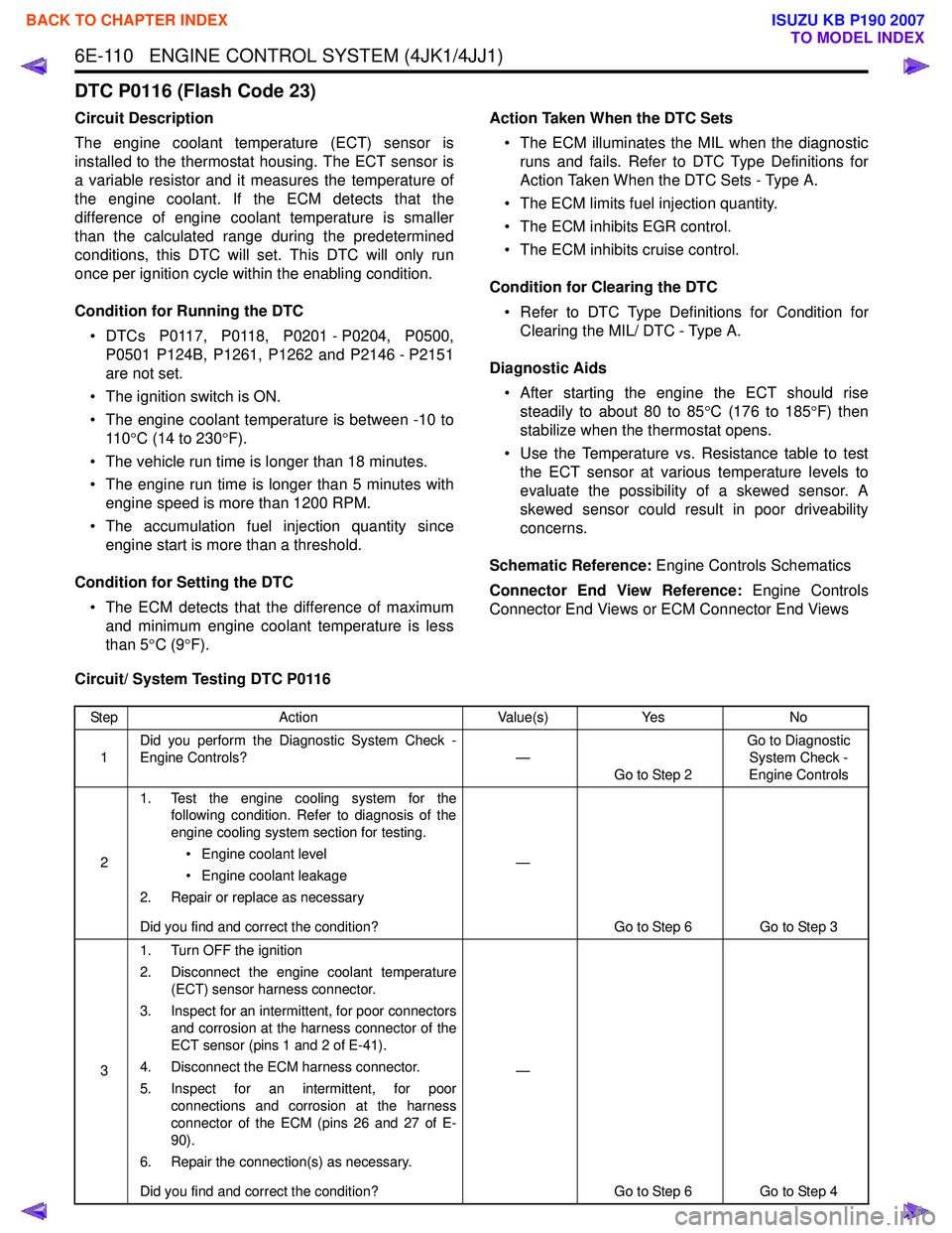
DTC P0116 (Flash Code 23)
Circuit Description
The engine coolant temperature (ECT) sensor is
installed to the thermostat housing. The ECT sensor is
a variable resistor and it measures the temperature of
the engine coolant. If the ECM detects that the
difference of engine coolant temperature is smaller
than the calculated range during the predetermined
conditions, this DTC will set. This DTC will only run
once per ignition cycle within the enabling condition.
Condition for Running the DTC • DTCs P0117, P0118, P0201 - P0204, P0500, P0501 P124B, P1261, P1262 and P2146 - P2151
are not set.
• The ignition switch is ON.
• The engine coolant temperature is between -10 to 11 0 °C (14 to 230 °F).
• The vehicle run time is longer than 18 minutes.
• The engine run time is longer than 5 minutes with engine speed is more than 1200 RPM.
• The accumulation fuel injection quantity since engine start is more than a threshold.
Condition for Setting the DTC • The ECM detects that the difference of maximum and minimum engine coolant temperature is less
than 5 °C (9 °F). Action Taken When the DTC Sets
• The ECM illuminates the MIL when the diagnostic runs and fails. Refer to DTC Type Definitions for
Action Taken When the DTC Sets - Type A.
• The ECM limits fuel injection quantity.
• The ECM inhibits EGR control.
• The ECM inhibits cruise control.
Condition for Clearing the DTC • Refer to DTC Type Definitions for Condition for Clearing the MIL/ DTC - Type A.
Diagnostic Aids • After starting the engine the ECT should rise steadily to about 80 to 85 °C (176 to 185 °F) then
stabilize when the thermostat opens.
• Use the Temperature vs. Resistance table to test the ECT sensor at various temperature levels to
evaluate the possibility of a skewed sensor. A
skewed sensor could result in poor driveability
concerns.
Schematic Reference: Engine Controls Schematics
Connector End View Reference: Engine Controls
Connector End Views or ECM Connector End Views
Circuit/ System Testing DTC P0116
Step Action Value(s)Yes No
1 Did you perform the Diagnostic System Check -
Engine Controls? —
Go to Step 2 Go to Diagnostic
System Check -
Engine Controls
2 1. Test the engine cooling system for the
following condition. Refer to diagnosis of the
engine cooling system section for testing.
• Engine coolant level
• Engine coolant leakage
2. Repair or replace as necessary
Did you find and correct the condition? —
Go to Step 6 Go to Step 3
3 1. Turn OFF the ignition
2. Disconnect the engine coolant temperature (ECT) sensor harness connector.
3. Inspect for an intermittent, for poor connectors and corrosion at the harness connector of the
ECT sensor (pins 1 and 2 of E-41).
4. Disconnect the ECM harness connector.
5. Inspect for an intermittent, for poor connections and corrosion at the harness
connector of the ECM (pins 26 and 27 of E-
90).
6. Repair the connection(s) as necessary.
Did you find and correct the condition? —
Go to Step 6 Go to Step 4
BACK TO CHAPTER INDEX
TO MODEL INDEX
ISUZU KB P190 2007
Page 1752 of 6020
ENGINE CONTROL SYSTEM (4JK1/4JJ1) 6E-135
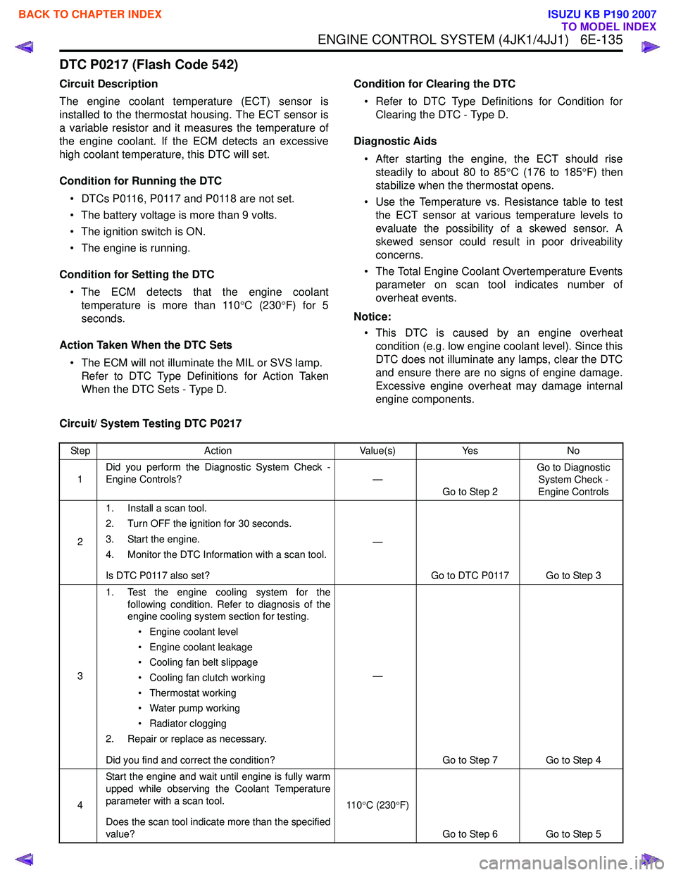
DTC P0217 (Flash Code 542)
Circuit Description
The engine coolant temperature (ECT) sensor is
installed to the thermostat housing. The ECT sensor is
a variable resistor and it measures the temperature of
the engine coolant. If the ECM detects an excessive
high coolant temperature, this DTC will set.
Condition for Running the DTC • DTCs P0116, P0117 and P0118 are not set.
• The battery voltage is more than 9 volts.
• The ignition switch is ON.
• The engine is running.
Condition for Setting the DTC • The ECM detects that the engine coolant temperature is more than 110 °C (230 °F) for 5
seconds.
Action Taken When the DTC Sets • The ECM will not illuminate the MIL or SVS lamp. Refer to DTC Type Definitions for Action Taken
When the DTC Sets - Type D. Condition for Clearing the DTC
• Refer to DTC Type Definitions for Condition for Clearing the DTC - Type D.
Diagnostic Aids • After starting the engine, the ECT should rise steadily to about 80 to 85 °C (176 to 185 °F) then
stabilize when the thermostat opens.
• Use the Temperature vs. Resistance table to test the ECT sensor at various temperature levels to
evaluate the possibility of a skewed sensor. A
skewed sensor could result in poor driveability
concerns.
• The Total Engine Coolant Overtemperature Events parameter on scan tool indicates number of
overheat events.
Notice: • This DTC is caused by an engine overheat condition (e.g. low engine coolant level). Since this
DTC does not illuminate any lamps, clear the DTC
and ensure there are no signs of engine damage.
Excessive engine overheat may damage internal
engine components.
Circuit/ System Testing DTC P0217
Step Action Value(s)Yes No
1 Did you perform the Diagnostic System Check -
Engine Controls? —
Go to Step 2 Go to Diagnostic
System Check -
Engine Controls
2 1. Install a scan tool.
2. Turn OFF the ignition for 30 seconds.
3. Start the engine.
4. Monitor the DTC Information with a scan tool.
Is DTC P0117 also set? —
Go to DTC P0117 Go to Step 3
3 1. Test the engine cooling system for the
following condition. Refer to diagnosis of the
engine cooling system section for testing.
• Engine coolant level
• Engine coolant leakage
• Cooling fan belt slippage
• Cooling fan clutch working
• Thermostat working
• Water pump working
• Radiator clogging
2. Repair or replace as necessary.
Did you find and correct the condition? —
Go to Step 7 Go to Step 4
4 Start the engine and wait until engine is fully warm
upped while observing the Coolant Temperature
parameter with a scan tool.
Does the scan tool indicate more than the specified
value? 11 0
°C (230 °F)
Go to Step 6 Go to Step 5
BACK TO CHAPTER INDEX
TO MODEL INDEX
ISUZU KB P190 2007
Page 1954 of 6020
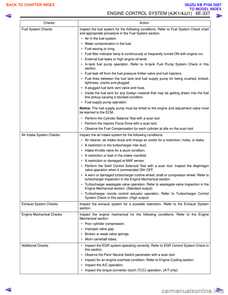
ENGINE CONTROL SYSTEM (4JK1/4JJ1) 6E-337
Fuel System ChecksInspect the fuel system for the following conditions. Refer to Fuel System Check chart
and appropriate procedure in the Fuel System section.
• Air in the fuel system.
• Water contamination in the fuel.
• Fuel waxing or icing.
• Fuel filter indicator lamp is continuously or frequently turned ON with engine run.
• External fuel leaks or high engine oil level.
• In-tank fuel pump operation. Refer to In-tank Fuel Pump System Check in this section.
• Fuel leak off from the fuel pressure limiter valve and fuel injectors.
• Fuel lines between the fuel tank and fuel supply pump for being crushed, kinked, tightness, cracks and plugged.
• A plugged fuel tank vent valve and hose.
• Inside the fuel tank for any foreign material that may be getting drawn into the fuel line pickup causing a blocked condition.
• Fuel supply pump operation.
Notice: The fuel supply pump must be timed to the engine and adjustment value must
be learned to the ECM.
• Perform the Cylinder Balance Test with a scan tool.
• Perform the Injector Force Drive with a scan tool.
• Observe the Fuel Compensation for each cylinder at idle on the scan tool.
Air Intake System Checks Inspect the air intake system for the following conditions.
• Air cleaner, air intake ducts and charge air cooler for a restriction, holes, or leaks.
• A restriction in the turbocharger inlet duct.
• Intake throttle valve for a stuck condition.
• A restriction or leak in the intake manifold.
• A restriction or damaged at MAF sensor.
• Perform the Swirl Control Solenoid Test with a scan tool. Inspect the diaphragm valve operation when it commanded ON/ OFF.
• A worn or damaged turbocharger turbine wheel, shaft or compressor wheel. Refer to turbocharger inspection in the Engine Mechanical section.
• Turbocharger wastegate valve operation. Refer to wastegate valve inspection in the Engine Mechanical section. (Standard output)
• Turbocharger nozzle control actuator operation. Refer to Turbocharger Control System Check in this section. (High output)
Exhaust System Checks Inspect the exhaust system for a possible restriction. Refer to the Exhaust System
section.
Engine Mechanical Checks Inspect the engine mechanical for the following conditions. Refer to the Engine
Mechanical section.
• Poor cylinder compression.
• Improper valve gap.
• Broken or weak valve springs.
• Worn camshaft lobes.
Additional Checks • Inspect the EGR system operating correctly. Refer to EGR Control System Check in
this section.
• Observe the Park/ Neutral Switch parameter with a scan tool.
• Inspect for an engine overheat condition. Refer to Engine Cooling section.
• Inspect the A/C operation.
• Inspect the torque converter clutch (TCC) operation. (A/T only).
Checks
Action
BACK TO CHAPTER INDEX
TO MODEL INDEX
ISUZU KB P190 2007
Page 1956 of 6020
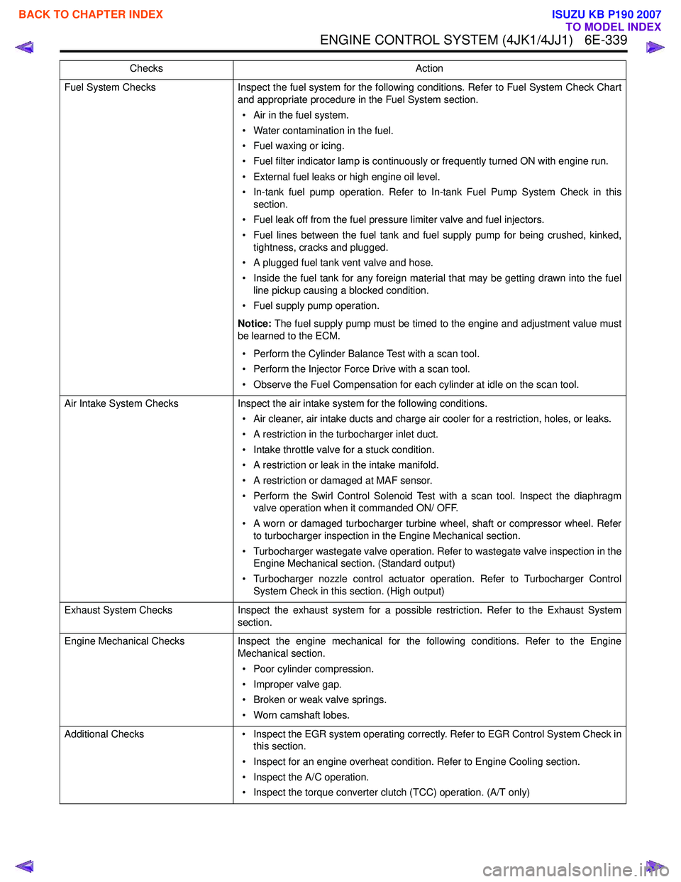
ENGINE CONTROL SYSTEM (4JK1/4JJ1) 6E-339
Fuel System ChecksInspect the fuel system for the following conditions. Refer to Fuel System Check Chart
and appropriate procedure in the Fuel System section.
• Air in the fuel system.
• Water contamination in the fuel.
• Fuel waxing or icing.
• Fuel filter indicator lamp is continuously or frequently turned ON with engine run.
• External fuel leaks or high engine oil level.
• In-tank fuel pump operation. Refer to In-tank Fuel Pump System Check in this section.
• Fuel leak off from the fuel pressure limiter valve and fuel injectors.
• Fuel lines between the fuel tank and fuel supply pump for being crushed, kinked, tightness, cracks and plugged.
• A plugged fuel tank vent valve and hose.
• Inside the fuel tank for any foreign material that may be getting drawn into the fuel line pickup causing a blocked condition.
• Fuel supply pump operation.
Notice: The fuel supply pump must be timed to the engine and adjustment value must
be learned to the ECM.
• Perform the Cylinder Balance Test with a scan tool.
• Perform the Injector Force Drive with a scan tool.
• Observe the Fuel Compensation for each cylinder at idle on the scan tool.
Air Intake System Checks Inspect the air intake system for the following conditions.
• Air cleaner, air intake ducts and charge air cooler for a restriction, holes, or leaks.
• A restriction in the turbocharger inlet duct.
• Intake throttle valve for a stuck condition.
• A restriction or leak in the intake manifold.
• A restriction or damaged at MAF sensor.
• Perform the Swirl Control Solenoid Test with a scan tool. Inspect the diaphragm valve operation when it commanded ON/ OFF.
• A worn or damaged turbocharger turbine wheel, shaft or compressor wheel. Refer to turbocharger inspection in the Engine Mechanical section.
• Turbocharger wastegate valve operation. Refer to wastegate valve inspection in the Engine Mechanical section. (Standard output)
• Turbocharger nozzle control actuator operation. Refer to Turbocharger Control System Check in this section. (High output)
Exhaust System Checks Inspect the exhaust system for a possible restriction. Refer to the Exhaust System
section.
Engine Mechanical Checks Inspect the engine mechanical for the following conditions. Refer to the Engine
Mechanical section.
• Poor cylinder compression.
• Improper valve gap.
• Broken or weak valve springs.
• Worn camshaft lobes.
Additional Checks • Inspect the EGR system operating correctly. Refer to EGR Control System Check in
this section.
• Inspect for an engine overheat condition. Refer to Engine Cooling section.
• Inspect the A/C operation.
• Inspect the torque converter clutch (TCC) operation. (A/T only)
Checks
Action
BACK TO CHAPTER INDEX
TO MODEL INDEX
ISUZU KB P190 2007
Page 1958 of 6020
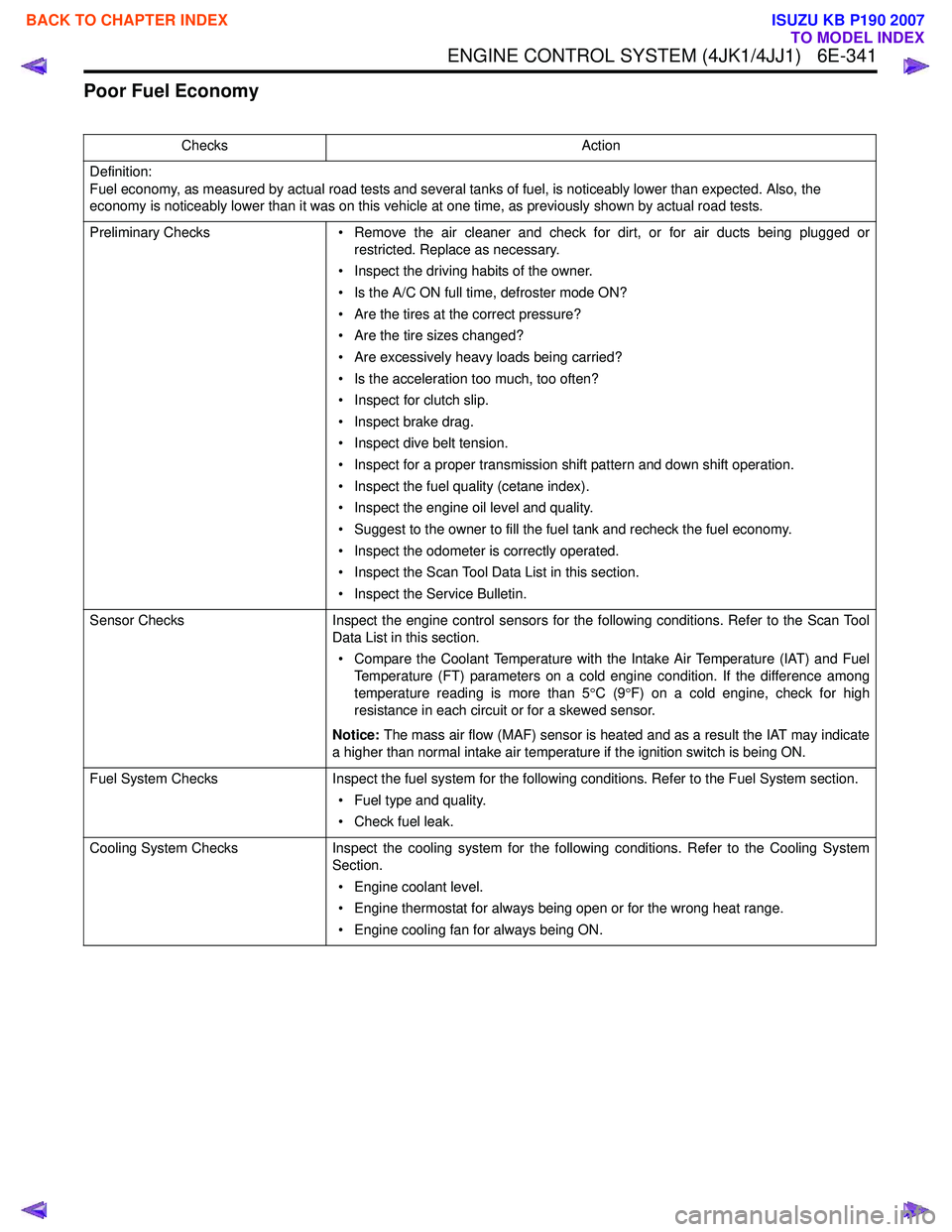
ENGINE CONTROL SYSTEM (4JK1/4JJ1) 6E-341
Poor Fuel Economy
ChecksAction
Definition:
Fuel economy, as measured by actual road tests and several tanks of fuel, is noticeably lower than expected. Also, the
economy is noticeably lower than it was on this vehicle at one time, as previously shown by actual road tests.
Preliminary Checks • Remove the air cleaner and check for dirt, or for air ducts being plugged or
restricted. Replace as necessary.
• Inspect the driving habits of the owner.
• Is the A/C ON full time, defroster mode ON?
• Are the tires at the correct pressure?
• Are the tire sizes changed?
• Are excessively heavy loads being carried?
• Is the acceleration too much, too often?
• Inspect for clutch slip.
• Inspect brake drag.
• Inspect dive belt tension.
• Inspect for a proper transmission shift pattern and down shift operation.
• Inspect the fuel quality (cetane index).
• Inspect the engine oil level and quality.
• Suggest to the owner to fill the fuel tank and recheck the fuel economy.
• Inspect the odometer is correctly operated.
• Inspect the Scan Tool Data List in this section.
• Inspect the Service Bulletin.
Sensor Checks Inspect the engine control sensors for the following conditions. Refer to the Scan Tool
Data List in this section.
• Compare the Coolant Temperature with the Intake Air Temperature (IAT) and Fuel Temperature (FT) parameters on a cold engine condition. If the difference among
temperature reading is more than 5 °C (9 °F) on a cold engine, check for high
resistance in each circuit or for a skewed sensor.
Notice: The mass air flow (MAF) sensor is heated and as a result the IAT may indicate
a higher than normal intake air temperature if the ignition switch is being ON.
Fuel System Checks Inspect the fuel system for the following conditions. Refer to the Fuel System section.
• Fuel type and quality.
• Check fuel leak.
Cooling System Checks Inspect the cooling system for the following conditions. Refer to the Cooling System
Section.
• Engine coolant level.
• Engine thermostat for always being open or for the wrong heat range.
• Engine cooling fan for always being ON.
BACK TO CHAPTER INDEX
TO MODEL INDEX
ISUZU KB P190 2007