Page 1360 of 6020
PAGE
Section 6A Engine Mechanical .................................................................................... 1361
Section 6B Engine Cooling .......................................................................................... 1524
Section 6C Fuel System ............................................................................................... 1542
Section 6D Engine Electrical ....................................................................................... 1589
Section 6E Engine Control System ............................................................................ 1618
Section 6F Exhaust System ........................................................................................ 1986
Section 6H Engine Speed Control System ................................................................ 1998
SECTION 6
ENGINE
TA BLE OF CONTENTS
ENGINE 6
4JK
1/4J J1 MODELS
BACK TO CHAPTER INDEX
TO MODEL INDEX
ISUZU KB P190 2007
Page 1372 of 6020
6A-12 ENGINE MECHANICAL (4JK1/4JJ1)
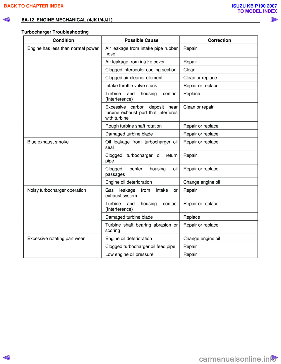
Turbocharger Troubleshooting
Condition Possible Cause Correction
Air leakage from intake pipe rubber
hose Repair
Air leakage from intake cover Repair
Clogged intercooler cooling section Clean
Clogged air cleaner element Clean or replace
Intake throttle valve stuck
Repair or replace
Turbine and housing contact
(Interference) Replace
Excessive carbon deposit near
turbine exhaust port that interferes
with turbine Clean or repair
Rough turbine shaft rotation Repair or replace
Engine has less than normal power
Damaged turbine blade Repair or replace
Oil leakage from turbocharger oil
seal Repair or replace
Clogged turbocharger oil return
pipe Repair
Clogged center housing oil
passages Repair or replace
Blue exhaust smoke
Engine oil deterioration Change engine oil
Gas leakage from intake or
exhaust system Repair
Turbine and housing contact
(Interference) Repair or replace
Damaged turbine blade
Replace
Noisy turbocharger operation
Turbine shaft bearing abrasion or
scoring Repair or replace
Engine oil deterioration
Change engine oil
Clogged turbocharger oil feed pipe Repair
Excessive rotating part wear
Low engine oil pressure Repair
BACK TO CHAPTER INDEX
TO MODEL INDEX
ISUZU KB P190 2007
Page 1373 of 6020
ENGINE MECHANICAL (4JK1/4JJ1) 6A-13
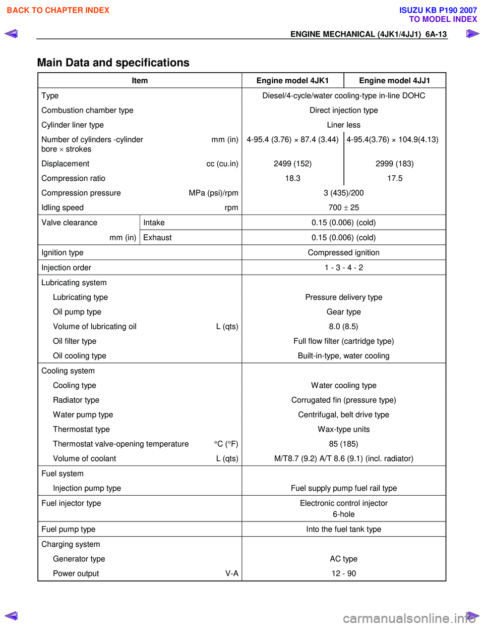
Main Data and specifications
Item Engine model 4JK1 Engine model 4JJ1
Type Diesel/4-cycle/water cooling-type in-line DOHC
Combustion chamber type Direct injection type
Cylinder liner type Liner less
Number of cylinders -cylinder
bore × strokes mm (in) 4-95.4 (3.76) × 87.4 (3.44) 4-95.4(3.76) × 104.9(4.13)
Displacement
cc (cu.in) 2499 (152) 2999 (183)
Compression ratio 18.3 17.5
Compression pressure MPa (psi)/rpm 3 (435)/200
Idling speed rpm 700 ± 25
Valve clearance Intake 0.15 (0.006) (cold)
mm (in) Exhaust 0.15 (0.006) (cold)
Ignition type Compressed ignition
Injection order 1 - 3 - 4 - 2
Lubricating system
Lubricating type Pressure delivery type
Oil pump type Gear type
Volume of lubricating oil L (qts) 8.0 (8.5)
Oil filter type Full flow filter (cartridge type)
Oil cooling type Built-in-type, water cooling
Cooling system
Cooling type W ater cooling type
Radiator type Corrugated fin (pressure type)
W ater pump type Centrifugal, belt drive type
Thermostat type W ax-type units
Thermostat valve-opening temperature °C ( °F) 85 (185)
Volume of coolant L (qts) M/T8.7 (9.2) A/T 8.6 (9.1) (incl. radiator)
Fuel system
Injection pump type Fuel supply pump fuel rail type
Fuel injector type Electronic control injector
6-hole
Fuel pump type Into the fuel tank type
Charging system
Generator type AC type
Power output V-A 12 - 90
BACK TO CHAPTER INDEX
TO MODEL INDEX
ISUZU KB P190 2007
Page 1411 of 6020
ENGINE MECHANICAL (4JK1/4JJ1) 6A-51
Removal
1. Partially drain the engine coolant.
2. Remove the radiator upper hose.
RTW 56FSH000101
3. Remove the fan guide.
RTW 46BSH000101
Legend
1. Fan Guide
2. Clips
3. Lower Fan Guide
4. Fan Shroud
4. Remove the cooling fan and fan pulley.
RTW 56ASH025401
5. Remove the A/C compressor drive belt and fan
belt.
6. Remove the crank pulley.
7. Remove the power steering pump with hose.
RTW 56ASH021101
Legend
1. Power Steering Pump
2. Nut
• Disconnect the bracket (1) of power steering oil
hose.
BACK TO CHAPTER INDEX
TO MODEL INDEX
ISUZU KB P190 2007
Page 1417 of 6020
ENGINE MECHANICAL (4JK1/4JJ1) 6A-57
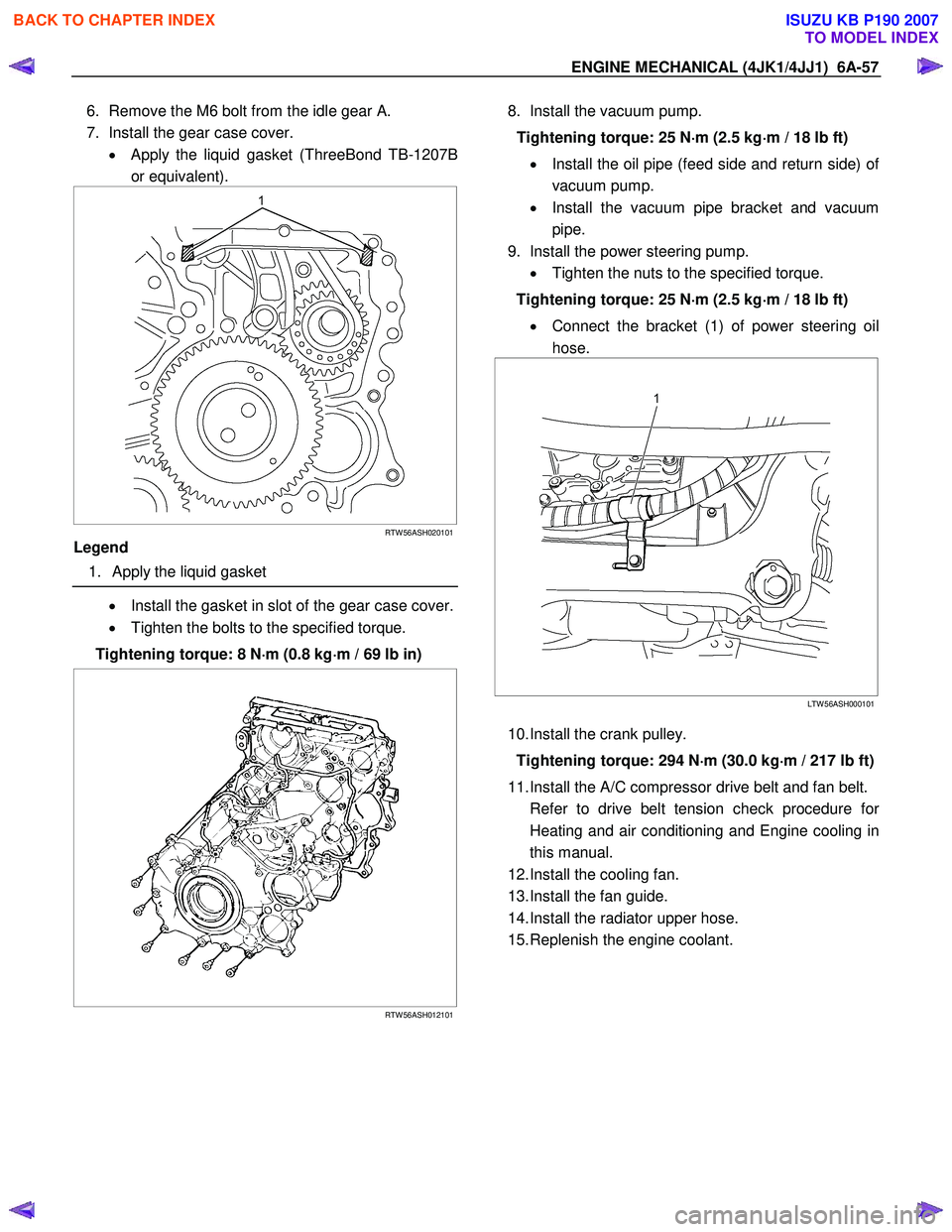
6. Remove the M6 bolt from the idle gear A.
7. Install the gear case cover. • Apply the liquid gasket (ThreeBond TB-1207B
or equivalent).
RTW 56ASH020101
Legend
1. Apply the liquid gasket
• Install the gasket in slot of the gear case cover.
• Tighten the bolts to the specified torque.
Tightening torque: 8 N ⋅
⋅⋅
⋅
m (0.8 kg ⋅
⋅⋅
⋅
m / 69 lb in)
RTW 56ASH012101
8. Install the vacuum pump.
Tightening torque: 25 N ⋅
⋅⋅
⋅
m (2.5 kg ⋅
⋅⋅
⋅
m / 18 lb ft)
• Install the oil pipe (feed side and return side) o
f
vacuum pump.
• Install the vacuum pipe bracket and vacuum
pipe.
9. Install the power steering pump. • Tighten the nuts to the specified torque.
Tightening torque: 25 N ⋅
⋅⋅
⋅
m (2.5 kg ⋅
⋅⋅
⋅
m / 18 lb ft)
• Connect the bracket (1) of power steering oil
hose.
LTW 56ASH000101
10. Install the crank pulley.
Tightening torque: 294 N ⋅
⋅⋅
⋅
m (30.0 kg ⋅
⋅⋅
⋅
m / 217 lb ft)
11. Install the A/C compressor drive belt and fan belt.
Refer to drive belt tension check procedure fo
r
Heating and air conditioning and Engine cooling in
this manual.
12. Install the cooling fan.
13. Install the fan guide.
14. Install the radiator upper hose.
15. Replenish the engine coolant.
BACK TO CHAPTER INDEX
TO MODEL INDEX
ISUZU KB P190 2007
Page 1433 of 6020
ENGINE MECHANICAL (4JK1/4JJ1) 6A-73
3. Remove the radiator upper hose.
RTW 56FSH000101
4. Remove the fan guide.
RTW 46BSH000101
Legend
1. Fan Guide
2. Clips
3. Lower Fan guide
4. Fan Shroud
5. Remove the cooling Fan.
RTW 56ASH025401
6. Rotate the crankshaft to make the No.1 cylinder
meet the compression top dead center (TDC).
RTW 76ASH001301
Legend
1. TDC
7. Remove the A/C compressor drive belt.
BACK TO CHAPTER INDEX
TO MODEL INDEX
ISUZU KB P190 2007
Page 1447 of 6020
ENGINE MECHANICAL (4JK1/4JJ1) 6A-87
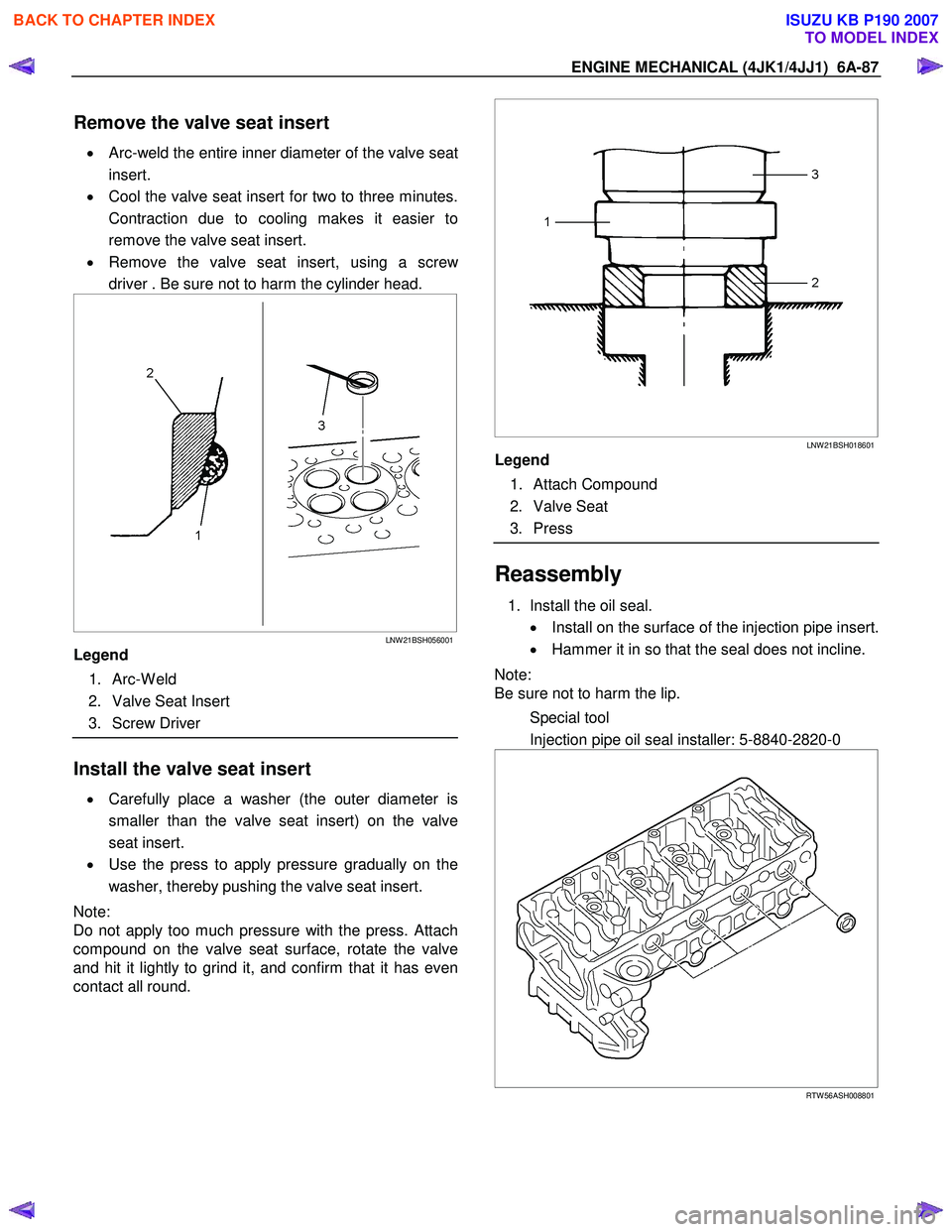
Remove the valve seat insert
• Arc-weld the entire inner diameter of the valve seat
insert.
• Cool the valve seat insert for two to three minutes.
Contraction due to cooling makes it easier to
remove the valve seat insert.
• Remove the valve seat insert, using a scre
w
driver . Be sure not to harm the cylinder head.
LNW 21BSH056001
Legend
1. Arc-W eld
2. Valve Seat Insert
3. Screw Driver
Install the valve seat insert
• Carefully place a washer (the outer diameter is
smaller than the valve seat insert) on the valve
seat insert.
• Use the press to apply pressure gradually on the
washer, thereby pushing the valve seat insert.
Note:
Do not apply too much pressure with the press. Attach
compound on the valve seat surface, rotate the valve
and hit it lightly to grind it, and confirm that it has even
contact all round.
LNW 21BSH018601
Legend
1. Attach Compound
2. Valve Seat
3. Press
Reassembly
1. Install the oil seal.
• Install on the surface of the injection pipe insert.
• Hammer it in so that the seal does not incline.
Note:
Be sure not to harm the lip.
Special tool
Injection pipe oil seal installer: 5-8840-2820-0
RTW 56ASH008801
BACK TO CHAPTER INDEX
TO MODEL INDEX
ISUZU KB P190 2007
Page 1458 of 6020
6A-98 ENGINE MECHANICAL (4JK1/4JJ1)
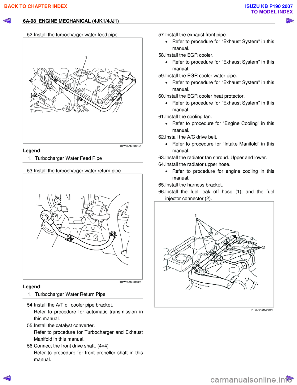
52. Install the turbocharger water feed pipe.
RTW 56ASH019101
Legend
1. Turbocharger W ater Feed Pipe
53. Install the turbocharger water return pipe.
RTW 56ASH019001
Legend
1. Turbocharger W ater Return Pipe
54 Install the A/T oil cooler pipe bracket.
Refer to procedure for automatic transmission in this manual.
55. Install the catalyst converter.
Refer to procedure for Turbocharger and Exhaust Manifold in this manual.
56. Connect the front drive shaft. (4 ×4)
Refer to procedure for front propeller shaft in this manual.
57. Install the exhaust front pipe.
• Refer to procedure for “Exhaust System” in this
manual.
58. Install the EGR cooler. • Refer to procedure for “Exhaust System” in this
manual.
59. Install the EGR cooler water pipe. • Refer to procedure for “Exhaust System” in this
manual.
60. Install the EGR cooler heat protector. • Refer to procedure for “Exhaust System” in this
manual.
61. Install the cooling fan. • Refer to procedure for “Engine Cooling” in this
manual.
62.Install the A/C drive belt. • Refer to procedure for “Intake Manifold” in this
manual.
63. Install the radiator fan shroud. Upper and lower.
64. Install the radiator upper hose. • Refer to procedure for engine cooling in this
manual.
65. Install the harness bracket.
66. Install the fuel leak off hose (1), and the fuel injector connector (2).
RTW 76ASH000101
BACK TO CHAPTER INDEX
TO MODEL INDEX
ISUZU KB P190 2007