2007 ISUZU KB P190 air condition
[x] Cancel search: air conditionPage 4338 of 6020
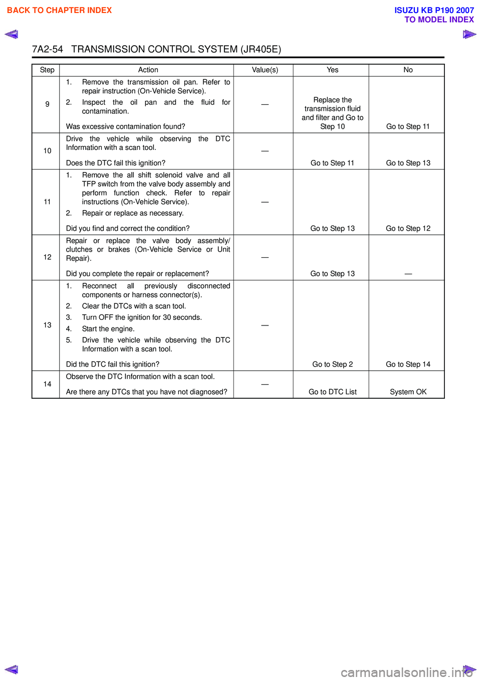
7A2-54 TRANSMISSION CONTROL SYSTEM (JR405E)
91. Remove the transmission oil pan. Refer to
repair instruction (On-Vehicle Service).
2. Inspect the oil pan and the fluid for contamination.
Was excessive contamination found? —
Replace the
transmission fluid
and filter and Go to Step 10 Go to Step 11
10 Drive the vehicle while observing the DTC
Information with a scan tool.
Does the DTC fail this ignition? —
Go to Step 11 Go to Step 13
11 1. Remove the all shift solenoid valve and all
TFP switch from the valve body assembly and
perform function check. Refer to repair
instructions (On-Vehicle Service).
2. Repair or replace as necessary.
Did you find and correct the condition? —
Go to Step 13 Go to Step 12
12 Repair or replace the valve body assembly/
clutches or brakes (On-Vehicle Service or Unit
Repair).
Did you complete the repair or replacement? —
Go to Step 13 —
13 1. Reconnect all previously disconnected
components or harness connector(s).
2. Clear the DTCs with a scan tool.
3. Turn OFF the ignition for 30 seconds.
4. Start the engine.
5. Drive the vehicle while observing the DTC Information with a scan tool.
Did the DTC fail this ignition? —
Go to Step 2 Go to Step 14
14 Observe the DTC Information with a scan tool.
Are there any DTCs that you have not diagnosed? —
Go to DTC List System OK
Step
Action Value(s)Yes No
BACK TO CHAPTER INDEX
TO MODEL INDEX
ISUZU KB P190 2007
Page 4340 of 6020
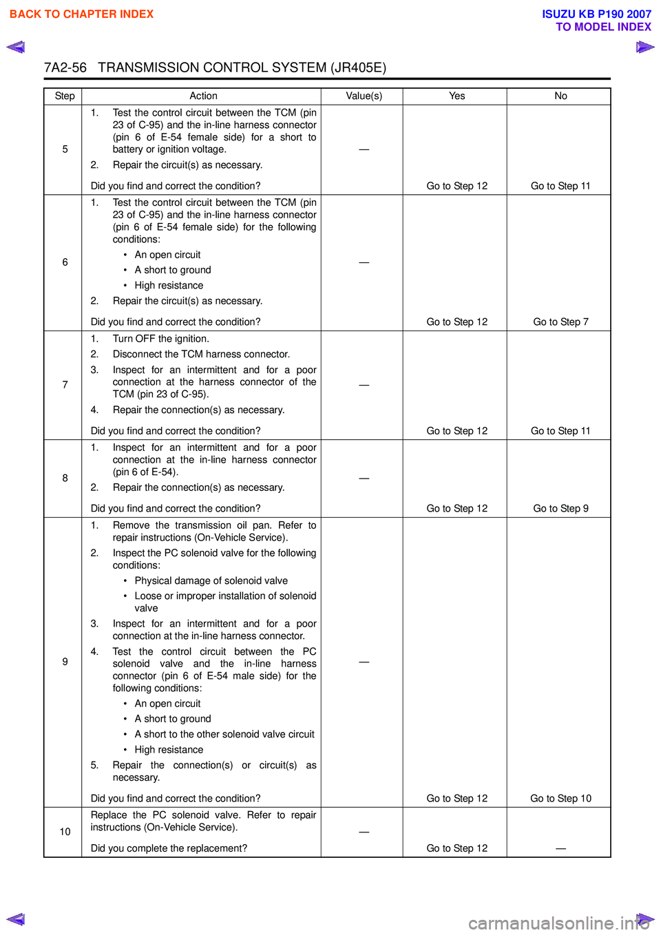
7A2-56 TRANSMISSION CONTROL SYSTEM (JR405E)
51. Test the control circuit between the TCM (pin
23 of C-95) and the in-line harness connector
(pin 6 of E-54 female side) for a short to
battery or ignition voltage.
2. Repair the circuit(s) as necessary.
Did you find and correct the condition? —
Go to Step 12 Go to Step 11
6 1. Test the control circuit between the TCM (pin
23 of C-95) and the in-line harness connector
(pin 6 of E-54 female side) for the following
conditions:
• An open circuit
• A short to ground
• High resistance
2. Repair the circuit(s) as necessary.
Did you find and correct the condition? —
Go to Step 12 Go to Step 7
7 1. Turn OFF the ignition.
2. Disconnect the TCM harness connector.
3. Inspect for an intermittent and for a poor connection at the harness connector of the
TCM (pin 23 of C-95).
4. Repair the connection(s) as necessary.
Did you find and correct the condition? —
Go to Step 12 Go to Step 11
8 1. Inspect for an intermittent and for a poor
connection at the in-line harness connector
(pin 6 of E-54).
2. Repair the connection(s) as necessary.
Did you find and correct the condition? —
Go to Step 12 Go to Step 9
9 1. Remove the transmission oil pan. Refer to
repair instructions (On-Vehicle Service).
2. Inspect the PC solenoid valve for the following conditions:
• Physical damage of solenoid valve
• Loose or improper installation of solenoid valve
3. Inspect for an intermittent and for a poor connection at the in-line harness connector.
4. Test the control circuit between the PC solenoid valve and the in-line harness
connector (pin 6 of E-54 male side) for the
following conditions:
• An open circuit
• A short to ground
• A short to the other solenoid valve circuit
• High resistance
5. Repair the connection(s) or circuit(s) as necessary.
Did you find and correct the condition? —
Go to Step 12 Go to Step 10
10 Replace the PC solenoid valve. Refer to repair
instructions (On-Vehicle Service).
Did you complete the replacement? —
Go to Step 12 —
Step
Action Value(s)Yes No
BACK TO CHAPTER INDEX
TO MODEL INDEX
ISUZU KB P190 2007
Page 4343 of 6020
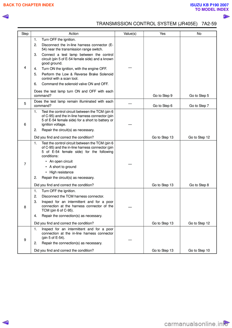
TRANSMISSION CONTROL SYSTEM (JR405E) 7A2-59
41. Turn OFF the ignition.
2. Disconnect the in-line harness connector (E- 54) near the transmission range switch.
3. Connect a test lamp between the control circuit (pin 5 of E-54 female side) and a known
good ground.
4. Turn ON the ignition, with the engine OFF.
5. Perform the Low & Reverse Brake Solenoid control with a scan tool.
6. Command the solenoid valve ON and OFF.
Does the test lamp turn ON and OFF with each
command? —
Go to Step 9 Go to Step 5
5 Does the test lamp remain illuminated with each
command? —
Go to Step 6 Go to Step 7
6 1. Test the control circuit between the TCM (pin 6
of C-95) and the in-line harness connector (pin
5 of E-54 female side) for a short to battery or
ignition voltage.
2. Repair the circuit(s) as necessary.
Did you find and correct the condition? —
Go to Step 13 Go to Step 12
7 1. Test the control circuit between the TCM (pin 6
of C-95) and the in-line harness connector (pin
5 of E-54 female side) for the following
conditions:
• An open circuit
• A short to ground
• High resistance
2. Repair the circuit(s) as necessary.
Did you find and correct the condition? —
Go to Step 13 Go to Step 8
8 1. Turn OFF the ignition.
2. Disconnect the TCM harness connector.
3. Inspect for an intermittent and for a poor connection at the harness connector of the
TCM (pin 6 of C-95).
4. Repair the connection(s) as necessary.
Did you find and correct the condition? —
Go to Step 13 Go to Step 12
9 1. Inspect for an intermittent and for a poor
connection at the in-line harness connector
(pin 5 of E-54).
2. Repair the connection(s) as necessary.
Did you find and correct the condition? —
Go to Step 13 Go to Step 10
Step
Action Value(s)Yes No
BACK TO CHAPTER INDEX
TO MODEL INDEX
ISUZU KB P190 2007
Page 4344 of 6020
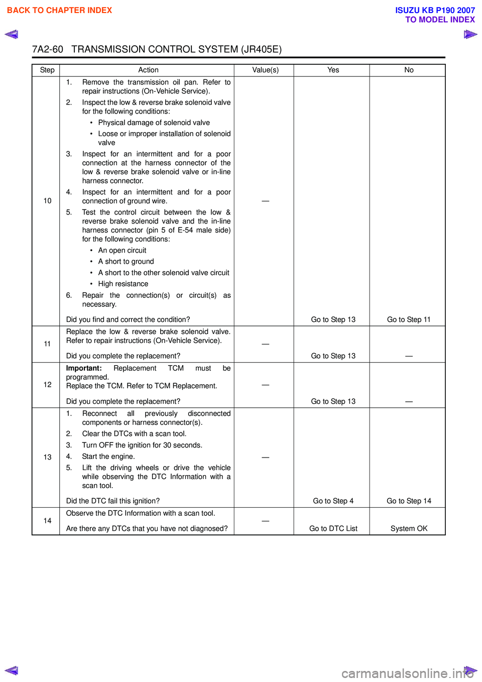
7A2-60 TRANSMISSION CONTROL SYSTEM (JR405E)
101. Remove the transmission oil pan. Refer to
repair instructions (On-Vehicle Service).
2. Inspect the low & reverse brake solenoid valve for the following conditions:
• Physical damage of solenoid valve
• Loose or improper installation of solenoid valve
3. Inspect for an intermittent and for a poor connection at the harness connector of the
low & reverse brake solenoid valve or in-line
harness connector.
4. Inspect for an intermittent and for a poor connection of ground wire.
5. Test the control circuit between the low & reverse brake solenoid valve and the in-line
harness connector (pin 5 of E-54 male side)
for the following conditions:
• An open circuit
• A short to ground
• A short to the other solenoid valve circuit
• High resistance
6. Repair the connection(s) or circuit(s) as necessary.
Did you find and correct the condition? —
Go to Step 13 Go to Step 11
11 Replace the low & reverse brake solenoid valve.
Refer to repair instructions (On-Vehicle Service).
Did you complete the replacement? —
Go to Step 13 —
12 Important:
Replacement TCM must be
programmed.
Replace the TCM. Refer to TCM Replacement.
Did you complete the replacement? —
Go to Step 13 —
13 1. Reconnect all previously disconnected
components or harness connector(s).
2. Clear the DTCs with a scan tool.
3. Turn OFF the ignition for 30 seconds.
4. Start the engine.
5. Lift the driving wheels or drive the vehicle while observing the DTC Information with a
scan tool.
Did the DTC fail this ignition? —
Go to Step 4 Go to Step 14
14 Observe the DTC Information with a scan tool.
Are there any DTCs that you have not diagnosed? —
Go to DTC List System OK
Step
Action Value(s)Yes No
BACK TO CHAPTER INDEX
TO MODEL INDEX
ISUZU KB P190 2007
Page 4346 of 6020
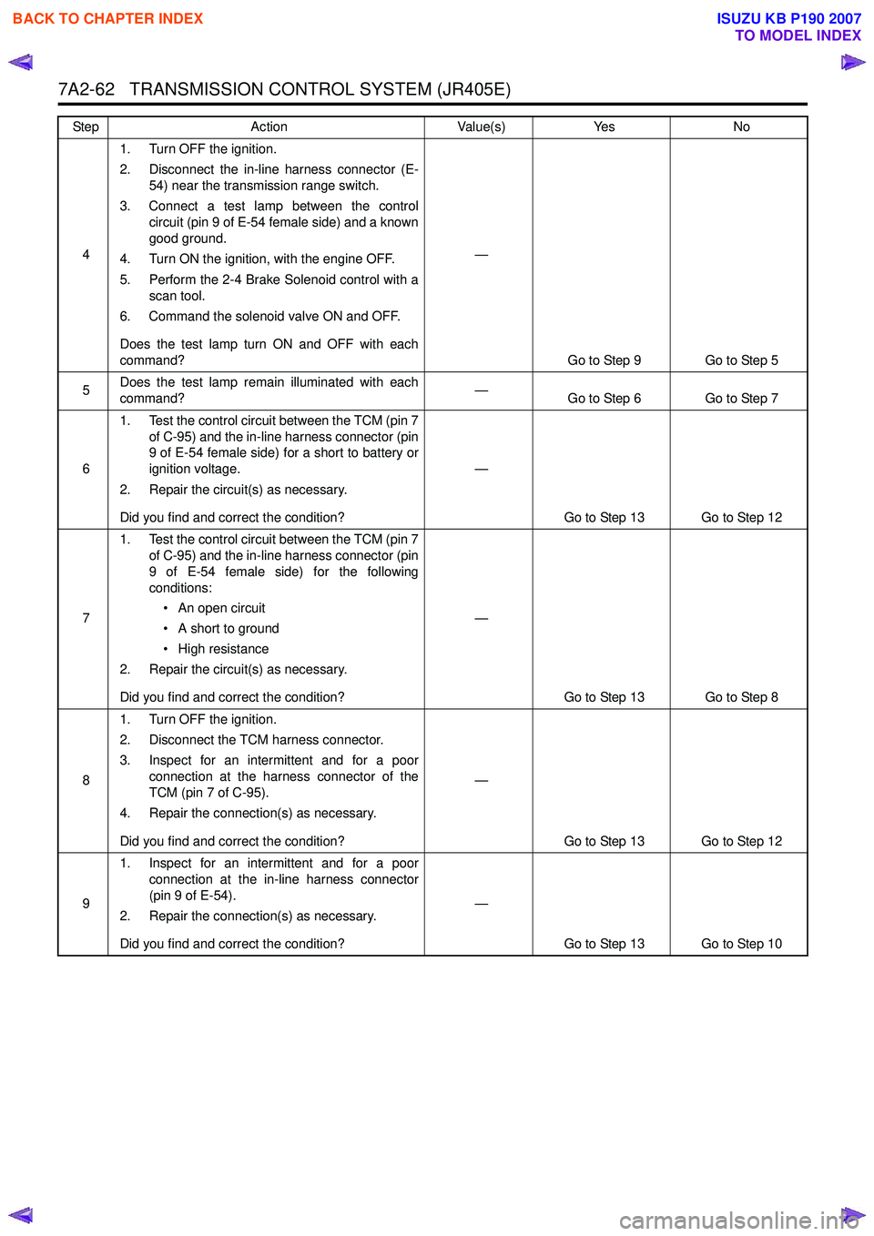
7A2-62 TRANSMISSION CONTROL SYSTEM (JR405E)
41. Turn OFF the ignition.
2. Disconnect the in-line harness connector (E- 54) near the transmission range switch.
3. Connect a test lamp between the control circuit (pin 9 of E-54 female side) and a known
good ground.
4. Turn ON the ignition, with the engine OFF.
5. Perform the 2-4 Brake Solenoid control with a scan tool.
6. Command the solenoid valve ON and OFF.
Does the test lamp turn ON and OFF with each
command? —
Go to Step 9 Go to Step 5
5 Does the test lamp remain illuminated with each
command? —
Go to Step 6 Go to Step 7
6 1. Test the control circuit between the TCM (pin 7
of C-95) and the in-line harness connector (pin
9 of E-54 female side) for a short to battery or
ignition voltage.
2. Repair the circuit(s) as necessary.
Did you find and correct the condition? —
Go to Step 13 Go to Step 12
7 1. Test the control circuit between the TCM (pin 7
of C-95) and the in-line harness connector (pin
9 of E-54 female side) for the following
conditions:
• An open circuit
• A short to ground
• High resistance
2. Repair the circuit(s) as necessary.
Did you find and correct the condition? —
Go to Step 13 Go to Step 8
8 1. Turn OFF the ignition.
2. Disconnect the TCM harness connector.
3. Inspect for an intermittent and for a poor connection at the harness connector of the
TCM (pin 7 of C-95).
4. Repair the connection(s) as necessary.
Did you find and correct the condition? —
Go to Step 13 Go to Step 12
9 1. Inspect for an intermittent and for a poor
connection at the in-line harness connector
(pin 9 of E-54).
2. Repair the connection(s) as necessary.
Did you find and correct the condition? —
Go to Step 13 Go to Step 10
Step
Action Value(s)Yes No
BACK TO CHAPTER INDEX
TO MODEL INDEX
ISUZU KB P190 2007
Page 4347 of 6020
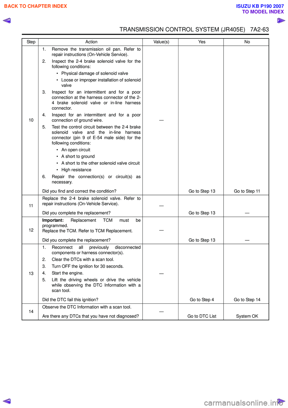
TRANSMISSION CONTROL SYSTEM (JR405E) 7A2-63
101. Remove the transmission oil pan. Refer to
repair instructions (On-Vehicle Service).
2. Inspect the 2-4 brake solenoid valve for the following conditions:
• Physical damage of solenoid valve
• Loose or improper installation of solenoid valve
3. Inspect for an intermittent and for a poor connection at the harness connector of the 2-
4 brake solenoid valve or in-line harness
connector.
4. Inspect for an intermittent and for a poor connection of ground wire.
5. Test the control circuit between the 2-4 brake solenoid valve and the in-line harness
connector (pin 9 of E-54 male side) for the
following conditions:
• An open circuit
• A short to ground
• A short to the other solenoid valve circuit
• High resistance
6. Repair the connection(s) or circuit(s) as necessary.
Did you find and correct the condition? —
Go to Step 13 Go to Step 11
11 Replace the 2-4 brake solenoid valve. Refer to
repair instructions (On-Vehicle Service).
Did you complete the replacement? —
Go to Step 13 —
12 Important:
Replacement TCM must be
programmed.
Replace the TCM. Refer to TCM Replacement.
Did you complete the replacement? —
Go to Step 13 —
13 1. Reconnect all previously disconnected
components or harness connector(s).
2. Clear the DTCs with a scan tool.
3. Turn OFF the ignition for 30 seconds.
4. Start the engine.
5. Lift the driving wheels or drive the vehicle while observing the DTC Information with a
scan tool.
Did the DTC fail this ignition? —
Go to Step 4 Go to Step 14
14 Observe the DTC Information with a scan tool.
Are there any DTCs that you have not diagnosed? —
Go to DTC List System OK
Step
Action Value(s)Yes No
BACK TO CHAPTER INDEX
TO MODEL INDEX
ISUZU KB P190 2007
Page 4349 of 6020
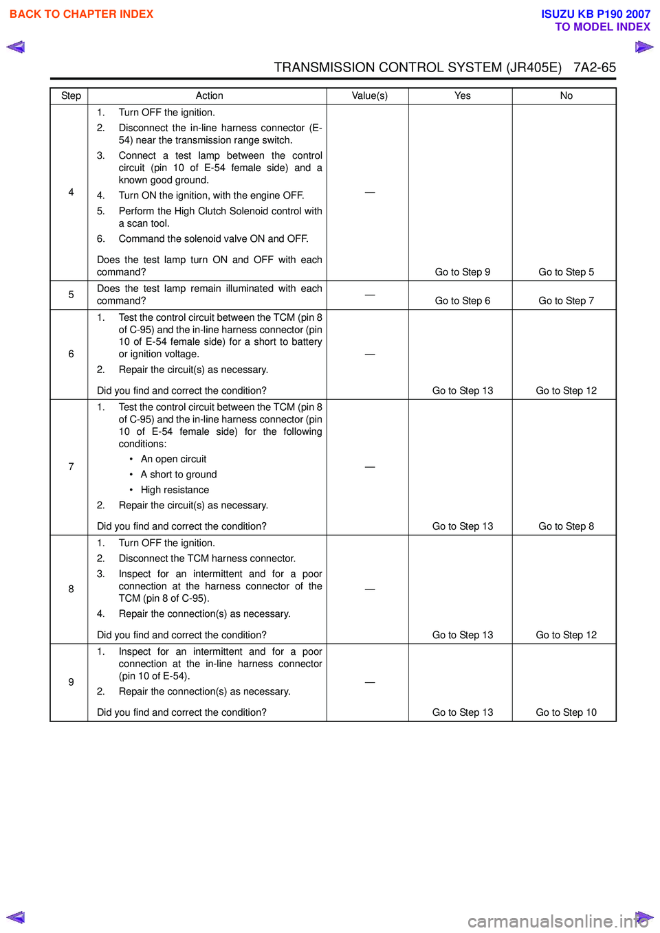
TRANSMISSION CONTROL SYSTEM (JR405E) 7A2-65
41. Turn OFF the ignition.
2. Disconnect the in-line harness connector (E- 54) near the transmission range switch.
3. Connect a test lamp between the control circuit (pin 10 of E-54 female side) and a
known good ground.
4. Turn ON the ignition, with the engine OFF.
5. Perform the High Clutch Solenoid control with a scan tool.
6. Command the solenoid valve ON and OFF.
Does the test lamp turn ON and OFF with each
command? —
Go to Step 9 Go to Step 5
5 Does the test lamp remain illuminated with each
command? —
Go to Step 6 Go to Step 7
6 1. Test the control circuit between the TCM (pin 8
of C-95) and the in-line harness connector (pin
10 of E-54 female side) for a short to battery
or ignition voltage.
2. Repair the circuit(s) as necessary.
Did you find and correct the condition? —
Go to Step 13 Go to Step 12
7 1. Test the control circuit between the TCM (pin 8
of C-95) and the in-line harness connector (pin
10 of E-54 female side) for the following
conditions:
• An open circuit
• A short to ground
• High resistance
2. Repair the circuit(s) as necessary.
Did you find and correct the condition? —
Go to Step 13 Go to Step 8
8 1. Turn OFF the ignition.
2. Disconnect the TCM harness connector.
3. Inspect for an intermittent and for a poor connection at the harness connector of the
TCM (pin 8 of C-95).
4. Repair the connection(s) as necessary.
Did you find and correct the condition? —
Go to Step 13 Go to Step 12
9 1. Inspect for an intermittent and for a poor
connection at the in-line harness connector
(pin 10 of E-54).
2. Repair the connection(s) as necessary.
Did you find and correct the condition? —
Go to Step 13 Go to Step 10
Step
Action Value(s)Yes No
BACK TO CHAPTER INDEX
TO MODEL INDEX
ISUZU KB P190 2007
Page 4350 of 6020
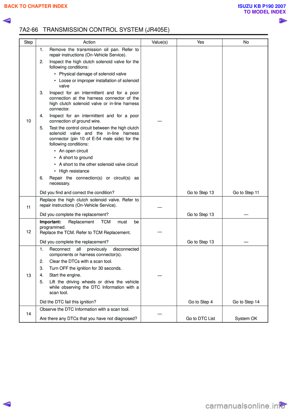
7A2-66 TRANSMISSION CONTROL SYSTEM (JR405E)
101. Remove the transmission oil pan. Refer to
repair instructions (On-Vehicle Service).
2. Inspect the high clutch solenoid valve for the following conditions:
• Physical damage of solenoid valve
• Loose or improper installation of solenoid valve
3. Inspect for an intermittent and for a poor connection at the harness connector of the
high clutch solenoid valve or in-line harness
connector.
4. Inspect for an intermittent and for a poor connection of ground wire.
5. Test the control circuit between the high clutch solenoid valve and the in-line harness
connector (pin 10 of E-54 male side) for the
following conditions:
• An open circuit
• A short to ground
• A short to the other solenoid valve circuit
• High resistance
6. Repair the connection(s) or circuit(s) as necessary.
Did you find and correct the condition? —
Go to Step 13 Go to Step 11
11 Replace the high clutch solenoid valve. Refer to
repair instructions (On-Vehicle Service).
Did you complete the replacement? —
Go to Step 13 —
12 Important:
Replacement TCM must be
programmed.
Replace the TCM. Refer to TCM Replacement.
Did you complete the replacement? —
Go to Step 13 —
13 1. Reconnect all previously disconnected
components or harness connector(s).
2. Clear the DTCs with a scan tool.
3. Turn OFF the ignition for 30 seconds.
4. Start the engine.
5. Lift the driving wheels or drive the vehicle while observing the DTC Information with a
scan tool.
Did the DTC fail this ignition? —
Go to Step 4 Go to Step 14
14 Observe the DTC Information with a scan tool.
Are there any DTCs that you have not diagnosed? —
Go to DTC List System OK
Step
Action Value(s)Yes No
BACK TO CHAPTER INDEX
TO MODEL INDEX
ISUZU KB P190 2007