2007 ISUZU KB P190 air condition
[x] Cancel search: air conditionPage 4378 of 6020
7A2-94 TRANSMISSION CONTROL SYSTEM (JR405E)
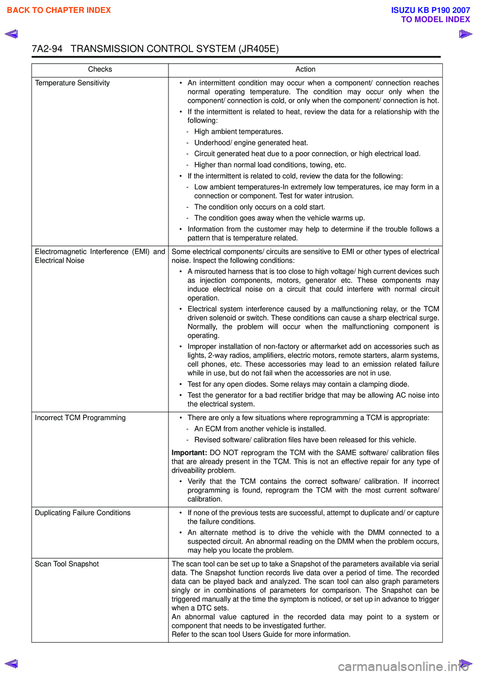
Temperature Sensitivity• An intermittent condition may occur when a component/ connection reaches
normal operating temperature. The condition may occur only when the
component/ connection is cold, or only when the component/ connection is hot.
• If the intermittent is related to heat, review the data for a relationship with the following:
- High ambient temperatures.
- Underhood/ engine generated heat.
- Circuit generated heat due to a poor connection, or high electrical load.
- Higher than normal load conditions, towing, etc.
• If the intermittent is related to cold, review the data for the following: - Low ambient temperatures-In extremely low temperatures, ice may form in a connection or component. Test for water intrusion.
- The condition only occurs on a cold start.
- The condition goes away when the vehicle warms up.
• Information from the customer may help to determine if the trouble follows a pattern that is temperature related.
Electromagnetic Interference (EMI) and
Electrical Noise Some electrical components/ circuits are sensitive to EMI or other types of electrical
noise. Inspect the following conditions:
• A misrouted harness that is too close to high voltage/ high current devices such as injection components, motors, generator etc. These components may
induce electrical noise on a circuit that could interfere with normal circuit
operation.
• Electrical system interference caused by a malfunctioning relay, or the TCM driven solenoid or switch. These conditions can cause a sharp electrical surge.
Normally, the problem will occur when the malfunctioning component is
operating.
• Improper installation of non-factory or aftermarket add on accessories such as lights, 2-way radios, amplifiers, electric motors, remote starters, alarm systems,
cell phones, etc. These accessories may lead to an emission related failure
while in use, but do not fail when the accessories are not in use.
• Test for any open diodes. Some relays may contain a clamping diode.
• Test the generator for a bad rectifier bridge that may be allowing AC noise into the electrical system.
Incorrect TCM Programming • There are only a few situations where reprogramming a TCM is appropriate:
- An ECM from another vehicle is installed.
- Revised software/ calibration files have been released for this vehicle.
Important: DO NOT reprogram the TCM with the SAME software/ calibration files
that are already present in the TCM. This is not an effective repair for any type of
driveability problem.
• Verify that the TCM contains the correct software/ calibration. If incorrect programming is found, reprogram the TCM with the most current software/
calibration.
Duplicating Failure Conditions • If none of the previous tests are successful, attempt to duplicate and/ or capture
the failure conditions.
• An alternate method is to drive the vehicle with the DMM connected to a suspected circuit. An abnormal reading on the DMM when the problem occurs,
may help you locate the problem.
Scan Tool Snapshot The scan tool can be set up to take a Snapshot of the parameters available via serial
data. The Snapshot function records live data over a period of time. The recorded
data can be played back and analyzed. The scan tool can also graph parameters
singly or in combinations of parameters for comparison. The Snapshot can be
triggered manually at the time the symptom is noticed, or set up in advance to trigger
when a DTC sets.
An abnormal value captured in the recorded data may point to a system or
component that needs to be investigated further.
Refer to the scan tool Users Guide for more information.
Checks
Action
BACK TO CHAPTER INDEX
TO MODEL INDEX
ISUZU KB P190 2007
Page 4424 of 6020
7A2-140 TRANSMISSION CONTROL SYSTEM (JR405E)
• Electrically Erasable Programmable Read OnlyMemory (EEPROM)
This type of memory allows selected portions of
memory to be programmed while other portions
remain unchanged.
Certain learned values reside in the EEPROM,
such as:
- The vehicle identification number (VIN)
- The software/ calibrations identification numbers
- The control module security information
• Flash Read Only Memory-Flash Memory
Flash memory has increased memory storage capacity.
During programming, all information within this type of
memory is erased, and then replaced with entirely new
information.
Service Programming Methods
The two methods of programming a TCM are listed
below:
• Remote Programming
• Pass Thru Programming
For information on programming a TCM using one of
the methods listed above, refer to Service
Programming System (SPS) (Remote Procedure) or
Service Programming System (SPS) (Pass-Thru
Procedure).
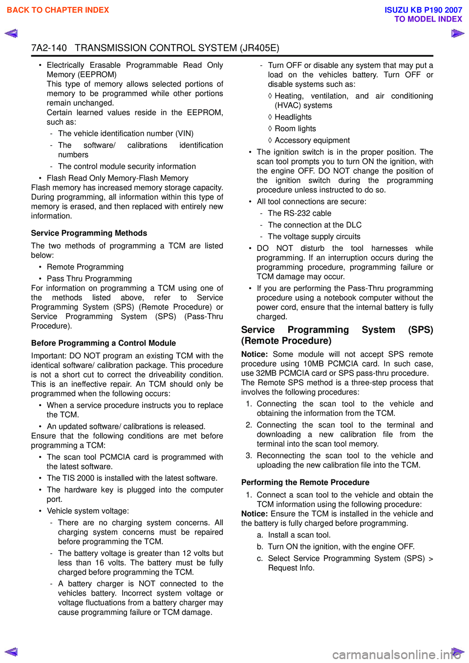
Before Programming a Control Module
Important: DO NOT program an existing TCM with the
identical software/ calibration package. This procedure
is not a short cut to correct the driveability condition.
This is an ineffective repair. An TCM should only be
programmed when the following occurs:
• When a service procedure instructs you to replace the TCM.
• An updated software/ calibrations is released.
Ensure that the following conditions are met before
programming a TCM:
• The scan tool PCMCIA card is programmed with the latest software.
• The TIS 2000 is installed with the latest software.
• The hardware key is plugged into the computer port.
• Vehicle system voltage:
- There are no charging system concerns. Allcharging system concerns must be repaired
before programming the TCM.
- The battery voltage is greater than 12 volts but less than 16 volts. The battery must be fully
charged before programming the TCM.
- A battery charger is NOT connected to the vehicles battery. Incorrect system voltage or
voltage fluctuations from a battery charger may
cause programming failure or TCM damage. - Turn OFF or disable any system that may put a
load on the vehicles battery. Turn OFF or
disable systems such as:
◊ Heating, ventilation, and air conditioning
(HVAC) systems
◊ Headlights
◊ Room lights
◊ Accessory equipment
• The ignition switch is in the proper position. The scan tool prompts you to turn ON the ignition, with
the engine OFF. DO NOT change the position of
the ignition switch during the programming
procedure unless instructed to do so.
• All tool connections are secure:
- The RS-232 cable
- The connection at the DLC
- The voltage supply circuits
• DO NOT disturb the tool harnesses while programming. If an interruption occurs during the
programming procedure, programming failure or
TCM damage may occur.
• If you are performing the Pass-Thru programming procedure using a notebook computer without the
power cord, ensure that the internal battery is fully
charged.
Service Programming System (SPS)
(Remote Procedure)
Notice: Some module will not accept SPS remote
procedure using 10MB PCMCIA card. In such case,
use 32MB PCMCIA card or SPS pass-thru procedure.
The Remote SPS method is a three-step process that
involves the following procedures:
1. Connecting the scan tool to the vehicle and obtaining the information from the TCM.
2. Connecting the scan tool to the terminal and downloading a new calibration file from the
terminal into the scan tool memory.
3. Reconnecting the scan tool to the vehicle and uploading the new calibration file into the TCM.
Performing the Remote Procedure 1. Connect a scan tool to the vehicle and obtain the TCM information using the following procedure:
Notice: Ensure the TCM is installed in the vehicle and
the battery is fully charged before programming.
a. Install a scan tool.
b. Turn ON the ignition, with the engine OFF.
c. Select Service Programming System (SPS) > Request Info.
BACK TO CHAPTER INDEX
TO MODEL INDEX
ISUZU KB P190 2007
Page 4473 of 6020
ON-VEHICLE SERVICE (JR405E) 7A3-19
Install or Connect
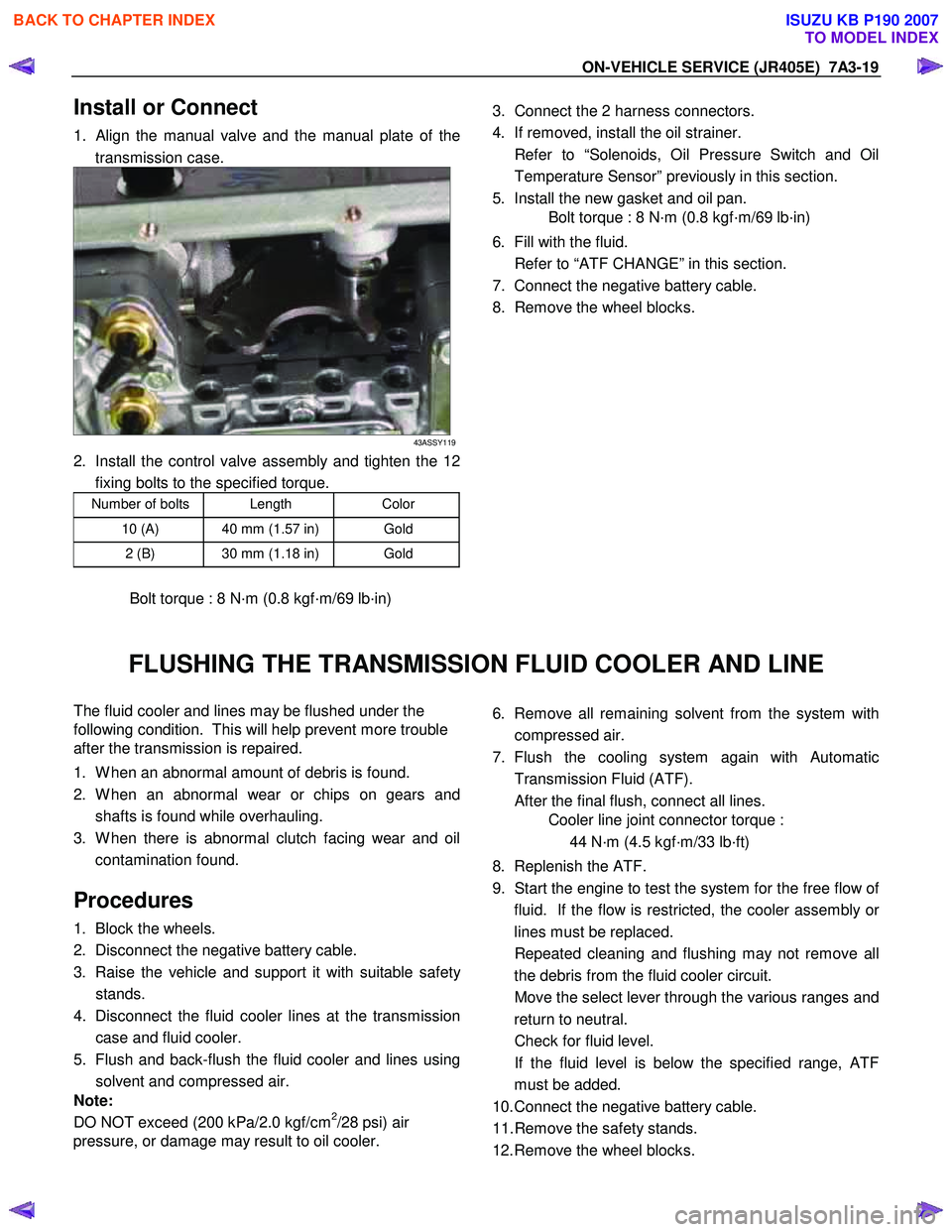
1. Align the manual valve and the manual plate of the
transmission case.
43ASSY119
2. Install the control valve assembly and tighten the 12 fixing bolts to the specified torque.
Number of bolts Length Color
10 (A) 40 mm (1.57 in) Gold
2 (B) 30 mm (1.18 in) Gold
Bolt torque : 8 N·m (0.8 kgf·m/69 lb·in)
3. Connect the 2 harness connectors.
4. If removed, install the oil strainer.
Refer to “Solenoids, Oil Pressure Switch and Oil Temperature Sensor” previously in this section.
5. Install the new gasket and oil pan.
Bolt torque : 8 N·m (0.8 kgf·m/69 lb·in)
6. Fill with the fluid.
Refer to “ATF CHANGE” in this section.
7. Connect the negative battery cable.
8. Remove the wheel blocks.
FLUSHING THE TRANSMISSION FLUID COOLER AND LINE
The fluid cooler and lines may be flushed under the
following condition. This will help prevent more trouble
after the transmission is repaired.
1. W hen an abnormal amount of debris is found.
2. W hen an abnormal wear or chips on gears and shafts is found while overhauling.
3. W hen there is abnormal clutch facing wear and oil contamination found.
Procedures
1. Block the wheels.
2. Disconnect the negative battery cable.
3. Raise the vehicle and support it with suitable safet
y
stands.
4. Disconnect the fluid cooler lines at the transmission case and fluid cooler.
5. Flush and back-flush the fluid cooler and lines using solvent and compressed air.
Note:
DO NOT exceed (200 kPa/2.0 kgf/cm
2/28 psi) air
pressure, or damage may result to oil cooler.
6. Remove all remaining solvent from the system with
compressed air.
7. Flush the cooling system again with Automatic Transmission Fluid (ATF).
After the final flush, connect all lines.
Cooler line joint connector torque :
44 N·m (4.5 kgf·m/33 lb·ft)
8. Replenish the ATF.
9. Start the engine to test the system for the free flow o
f
fluid. If the flow is restricted, the cooler assembly o
r
lines must be replaced.
Repeated cleaning and flushing may not remove all the debris from the fluid cooler circuit.
Move the select lever through the various ranges and return to neutral.
Check for fluid level.
If the fluid level is below the specified range, ATF must be added.
10. Connect the negative battery cable.
11. Remove the safety stands.
12. Remove the wheel blocks.
BACK TO CHAPTER INDEX
TO MODEL INDEX
ISUZU KB P190 2007
Page 4475 of 6020
ON-VEHICLE SERVICE (JR405E) 7A3-21
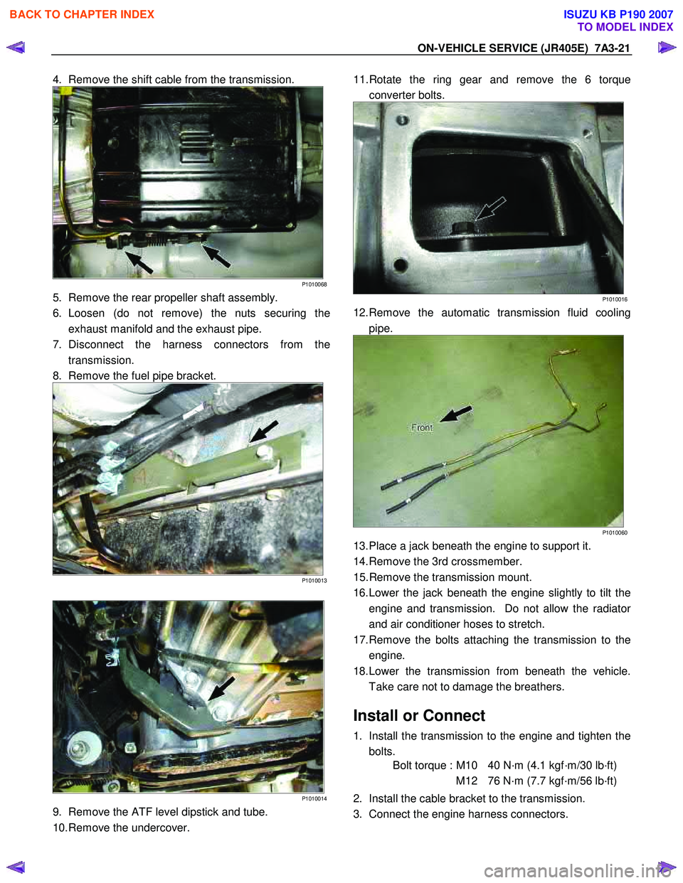
4. Remove the shift cable from the transmission.
P1010068
5. Remove the rear propeller shaft assembly.
6. Loosen (do not remove) the nuts securing the exhaust manifold and the exhaust pipe.
7. Disconnect the harness connectors from the transmission.
8. Remove the fuel pipe bracket.
P1010013
P1010014
9. Remove the ATF level dipstick and tube.
10. Remove the undercover.
11. Rotate the ring gear and remove the 6 torque
converter bolts.
P1010016
12. Remove the automatic transmission fluid cooling pipe.
P1010060
13. Place a jack beneath the engine to support it.
14. Remove the 3rd crossmember.
15. Remove the transmission mount.
16. Lower the jack beneath the engine slightly to tilt the engine and transmission. Do not allow the radiato
r
and air conditioner hoses to stretch.
17. Remove the bolts attaching the transmission to the engine.
18. Lower the transmission from beneath the vehicle. Take care not to damage the breathers.
Install or Connect
1. Install the transmission to the engine and tighten the bolts.
Bolt torque : M10 40 N·m (4.1 kgf·m/30 lb·ft)
M12 76 N·m (7.7 kgf·m/56 lb·ft)
2. Install the cable bracket to the transmission.
3. Connect the engine harness connectors.
BACK TO CHAPTER INDEX
TO MODEL INDEX
ISUZU KB P190 2007
Page 4479 of 6020
7A4-2 UNIT REPAIR (JR405E)
AUTOMATIC TRANSMISSION
DISASSEMBLY
Cleaning the automatic transmission
1. Use compressed steam and /or cleaning oil to thoroughly
clean the outside of the transmission before disassembly.
CAUTION:
Steam under high pressure may cause dirt particles
adhering to the transmission to fly through the air at great
speed. These particles can cause serious eye injury. Wear
protective goggles when steam-cleaning the outside of
the transmission.
2. During disassembly, clean the removed parts with cleaning oil. Dry the parts with compressed air.
Use Compressed air to clean the transmission oil holes
and oil passages.
Automatic transmission disassembly cautions
• Perform the disassembly procedure in a dust-free
environment to prevent the entry of foreign material into
the transmission.
• Inspect each transmission part as you remove it.
• Carefully check the oil pan and the magnet for foreign
material. This is a good way to estimate the transmission
condition.
• Use your bare hands or vinyl gloves to disassemble the
transmission. Do not use ordinary work gloves (loose
threads from the gloves may fall into the transmission and
cause problems).
• Use a plastic hammer to loosen the transmission case
and other aluminum parts during disassembly. Strike
around the parts lightly with the hammer. Do not pry
aluminum parts away from each other with a screwdriver
or similar object.
• Arrange the disassembled parts neatly in the order they
were removed. Cover the parts with a plastic sheet or
similar object to protect them from dust.
BACK TO CHAPTER INDEX
TO MODEL INDEX
ISUZU KB P190 2007
Page 4723 of 6020

7B1-4 Manual Transmission (MUX)
Troubleshooting
ConditionPossible Cause Correction
Abnormal Noise (Noisy in Neutral) Insufficient or improper lubricant Replenish or replace lubricant Flywheel pilot bearing worn or
broken Replace flywheel pilot bearing
Bearing(s) worn or broken (Input
shaft, counter shaft, and output
shaft) Replace bearing(s)
Gear tooth contact surfaces worn or
scuffed (Input shaft, counter shaft,
output shaft, and reverse idler gear) Replace gear(s)
Spline worn (Input shaft, output
shaft, counter shaft, and
synchronizer clutch hub) Replace worn parts
Transmission misalignment Realign transmission
Abnormal Noise (Noisy Operation) Insufficient or improper lubricant (Metallic rattling) Replenish or replace lubricant
Bearing(s) worn or broken (Hissing,
thumping, or bumping) Replace bearing(s)
Gear(s) worn, chipped, or cracked
(Growling, humming, or grinding) Replace gear(s)
Gears seizing on thrust face or
inner face free running (Squealing
at high speeds) Replace gear(s)
Gears lack of backlash between
meshing (Gear whining) Replace gear(s)
Hard Shifting Insufficient or improper lubricant Replenish or replace lubricant
Improper clutch pedal free play Readjust clutch pedal free play
Hard operating of change lever
caused insufficient grease Repair or regrease change lever
assembly
Change lever sliding portions worn Repair or replace applicable parts and regrease
Shift block sleeve movement failure Repair or replace sleeve
Shift rod and/or quadrant box
sliding face worn Replace worn parts
Shift arm and/or synchronizer
sleeve groove worn Replace worn parts
Collar, and/or gear thrust faces
worn (Input shaft and counter shaft
thrust play) Replace worn parts
Synchronizer parts worn Replace worn parts
BACK TO CHAPTER INDEX
TO MODEL INDEX
ISUZU KB P190 2007
Page 4741 of 6020
7B1-22 Manual Transmission (MUX)
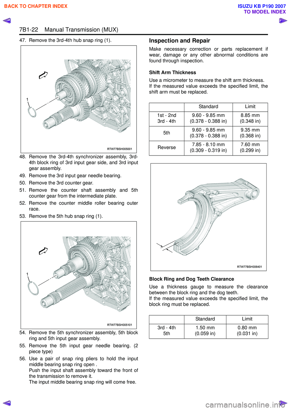
47. Remove the 3rd-4th hub snap ring (1).
48. Remove the 3rd-4th synchronizer assembly, 3rd-4th block ring of 3rd input gear side, and 3rd input
gear assembly.
49. Remove the 3rd input gear needle bearing.
50. Remove the 3rd counter gear.
51. Remove the counter shaft assembly and 5th counter gear from the intermediate plate.
52. Remove the counter middle roller bearing outer race.
53. Remove the 5th hub snap ring (1).
54. Remove the 5th synchronizer assembly, 5th block ring and 5th input gear assembly.
55. Remove the 5th input gear needle bearing. (2 piece type)
56. Use a pair of snap ring pliers to hold the input middle bearing snap ring open .
Push the input shaft assembly toward the front of
the transmission to remove it.
The input middle bearing snap ring will come free.Inspection and Repair
Make necessary correction or parts replacement if
wear, damage or any other abnormal conditions are
found through inspection.
Shift Arm Thickness
Use a micrometer to measure the shift arm thickness.
If the measured value exceeds the specified limit, the
shift arm must be replaced.
Block Ring and Dog Teeth Clearance
Use a thickness gauge to measure the clearance
between the block ring and the dog teeth.
If the measured value exceeds the specified limit, the
block ring must be replaced.
RTW77BSH005001
1
RTW77BSH005101
1
Standard Limit
1st - 2nd 3rd - 4th 9.60 - 9.85 mm
(0.378 - 0.388 in) 8.85 mm
(0.348 in)
5th 9.60 - 9.85 mm
(0.378 - 0.388 in) 9.35 mm
(0.368 in)
Reverse 7.85 - 8.10 mm
(0.309 - 0.319 in) 7.60 mm
(0.299 in)
Standard Limit
3rd - 4th 5th 1.50 mm
(0.059 in) 0.80 mm
(0.031 in)
RTW77BSH006401
BACK TO CHAPTER INDEX
TO MODEL INDEX
ISUZU KB P190 2007
Page 4760 of 6020
Manual Transmission (MUX) 7B1-41
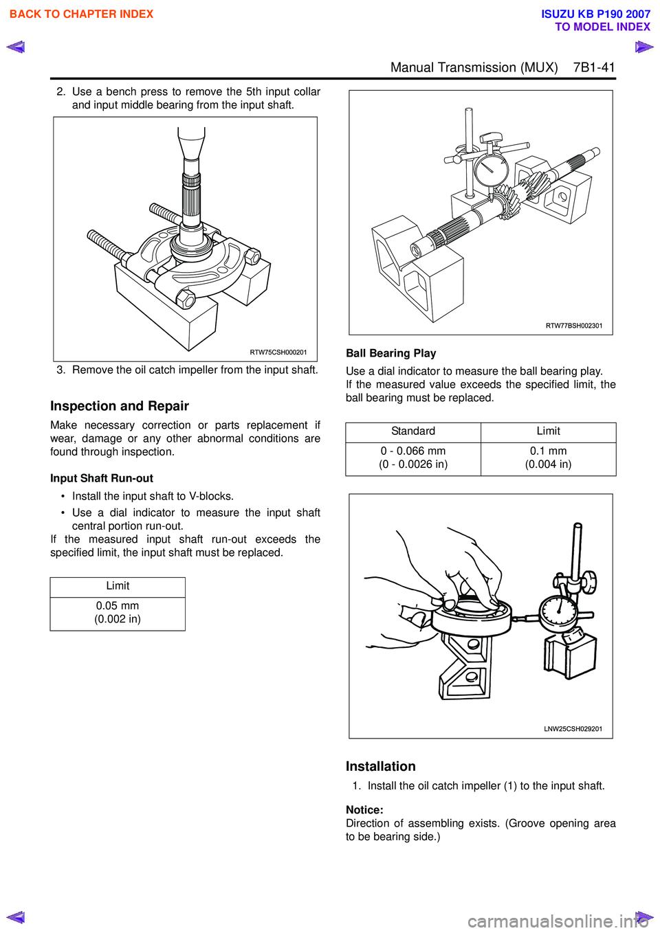
2. Use a bench press to remove the 5th input collarand input middle bearing from the input shaft.
3. Remove the oil catch impeller from the input shaft.
Inspection and Repair
Make necessary correction or parts replacement if
wear, damage or any other abnormal conditions are
found through inspection.
Input Shaft Run-out • Install the input shaft to V-blocks.
• Use a dial indicator to measure the input shaft central portion run-out.
If the measured input shaft run-out exceeds the
specified limit, the input shaft must be replaced. Ball Bearing Play
Use a dial indicator to measure the ball bearing play.
If the measured value exceeds the specified limit, the
ball bearing must be replaced.
Installation
1. Install the oil catch impeller (1) to the input shaft.
Notice:
Direction of assembling exists. (Groove opening area
to be bearing side.)
Limit
0.05 mm
(0.002 in)
RTW75CSH000201
Standard Limit
0 - 0.066 mm
(0 - 0.0026 in) 0.1 mm
(0.004 in)
RTW77BSH002301
LNW25CSH029201
BACK TO CHAPTER INDEX
TO MODEL INDEX
ISUZU KB P190 2007