Page 5214 of 6020
8A-276 ELECTRICAL-BODY AND CHASSIS
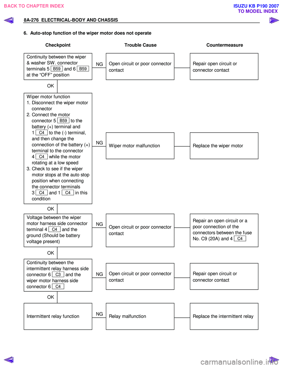
6. Auto-stop function of the wiper motor does not operate
Checkpoint Trouble Cause Countermeasure
Repair open circuit or
connector contact
Open circuit or poor connector
contact
NG
Repair open circuit or
connector contact
Open circuit or poor connector
contact
NG Continuity between the
intermittent relay harness side
connector 6
C3 and the
wiper motor harness side
connector 6
C4
Replace the intermittent relay
Relay malfunction
NG
Intermittent relay function
W iper motor function
1. Disconnect the wiper motor connector
2. Connect the motor connector 5
B59 to the
battery (+) terminal and
1
C4 to the (-) terminal,
and then change the
connection of the battery (+)
terminal to the connector
4
C4 while the motor
rotating at a low speed
3. Check to see if the wiper motor stops at the auto stop
position when connecting
the connector terminals
3
C4 and 1 C4 in this
condition
Continuity between the wiper
& washer SW . connector
terminals 5
B59 and 6 B59
at the “OFF” position
OK
Replace the wiper motor
W iper motor malfunction
NG
Repair an open circuit or a
poor connection of the
connectors between the fuse
No. C9 (20A) and 4
C4
Voltage between the wiper
motor harness side connector
terminal 4
C4 and the
ground (Should be battery
v oltage present)
Open circuit or poor connector
contact
NG
OK
OK
OK
BACK TO CHAPTER INDEX
TO MODEL INDEXISUZU KB P190 2007
Page 5309 of 6020
ELECTRICAL-BODY AND CHASSIS 8A-371
HEATER AND AIR CONDITIONING
PARTS LOCATION (RHD)
RTW 78AXF039101& RTW 78AXF045301
BACK TO CHAPTER INDEX TO MODEL INDEXISUZU KB P190 2007
Page 5350 of 6020
8A-412 ELECTRICAL-BODY AND CHASSIS
INSPECTION AND REPAIR
Harness side
D20 D5
Driver’s Side Power Window & Door Lock
Switch
1. Harness Side Connector Circuit
Check voltage and continuity between the switch harness side connector terminals as shown in the following table.
Terminal No. Wire
color Connecting to Check item Connectin
g terminal Check condition
Standard
Door lock SW
Driver’s Lock Continuity
(Lock) side door
Unlock No continuity
Door lock SW
Driver’s Lock No continuity
(Unlock) side door
Unlock Continuity
3 (D5) L/R Ground Continuity 3-Ground
- Continuity
4 (D5)
L/R Door lock
actuator (Lock) (Resistance)
4-5
- Continuity
There is some
resistance
5 (D5)
L Door lock
actuator
(Unlock)
5-4
- Continuity
There is some
resistance
1 (D5) LG/W Fuse
C21 (20A) Voltage 1- Ground
- Battery voltage
(Approx. 12V)
14-Ground
L/R
14 (D20)
13-Ground
L/Y
13 (D20)
BACK TO CHAPTER INDEX
TO MODEL INDEXISUZU KB P190 2007
Page 5372 of 6020
8A-434 ELECTRICAL-BODY AND CHASSIS
INSPECTION AND REPAIR
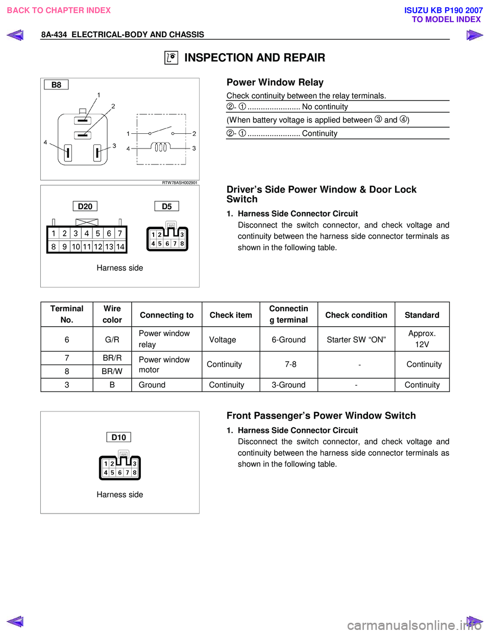
B8
RTW 78ASH002901
Power Window Relay
Check continuity between the relay terminals.
2- 1........................ No continuity
(W hen battery voltage is applied between
3 and 4)
2- 1........................ Continuity
Harness side
D20 D5
Driver’s Side Power Window & Door Lock
Switch
1. Harness Side Connector Circuit
Disconnect the switch connector, and check voltage and continuity between the harness side connector terminals as
shown in the following table.
Terminal No. Wire
color Connecting to Check item Connectin
g terminal Check condition Standard
6 G/R Power window
relay Voltage 6-Ground Starter SW “ON” Approx.
12V
7 BR/R Power window
8 BR/W motor
3 B Ground Continuity 3-Ground - Continuity
Harness side
D10
Front Passenger’s Power Window Switch
1. Harness Side Connector Circuit
Disconnect the switch connector, and check voltage and continuity between the harness side connector terminals as
shown in the following table.
Continuity
-
7-8
Continuity
BACK TO CHAPTER INDEX
TO MODEL INDEXISUZU KB P190 2007
Page 5478 of 6020
8A-540 ELECTRICAL-BODY AND CHASSIS
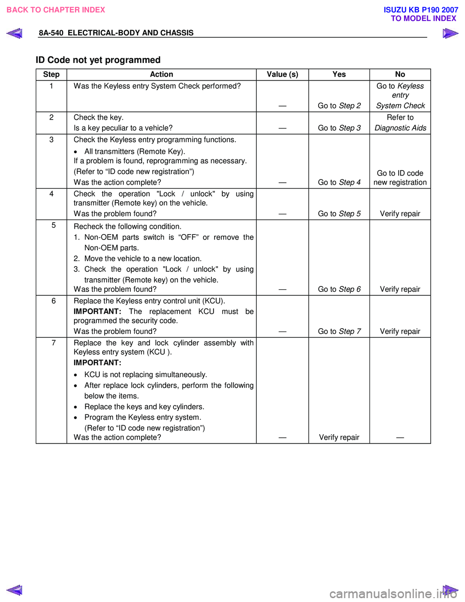
ID Code not yet programmed
Step Action Value (s) Yes No
1 W as the Keyless entry System Check performed?
— Go to Step 2 Go to
Keyless
entry
System Check
2 Check the key. Is a key peculiar to a vehicle? — Go to Step 3 Refer to
Diagnostic Aids
3 Check the Keyless entry programming functions.
• All transmitters (Remote Key).
If a problem is found, reprogramming as necessary.
(Refer to “ID code new registration”)
W as the action complete? — Go to Step 4 Go to ID code
new registration
4 Check the operation "Lock / unlock" by using transmitter (Remote key) on the vehicle.
W as the problem found? — Go to Step 5 Verify repair
5
Recheck the following condition.
1. Non-OEM parts switch is “OFF” or remove the Non-OEM parts.
2. Move the vehicle to a new location.
3. Check the operation "Lock / unlock" by using transmitter (Remote key) on the vehicle.
W as the problem found? — Go to Step 6 Verify repair
6 Replace the Keyless entry control unit (KCU).
IMPORTANT: The replacement KCU must be
programmed the security code.
W as the problem found? — Go to Step 7 Verify repair
7 Replace the key and lock cylinder assembly with
Keyless entry system (KCU ).
IMPORTANT:
• KCU is not replacing simultaneously.
• After replace lock cylinders, perform the following
below the items.
• Replace the keys and key cylinders.
• Program the Keyless entry system.
(Refer to “ID code new registration”)
W as the action complete? — Verify repair —
BACK TO CHAPTER INDEX
TO MODEL INDEXISUZU KB P190 2007
Page 5582 of 6020
Cruise Control – HFV6 Page 8C–4
NOTE Defined
A NOTE statement immediately precedes or follows an operating procedure, maintenance practice or condition that
requires highlighting. A NOTE statement also emphasises necessary characteristics of a diagnostic or repair procedure.
A NOTE statement is designed to:
• Clarify a procedure,
• Present additional information for accomplishing a procedure,
• Give insight into the reasons for performing a procedure in the recommended manner, and / or
• Present information that gives the technician the benefit of past experience in accomplishing a procedure with
greater ease.
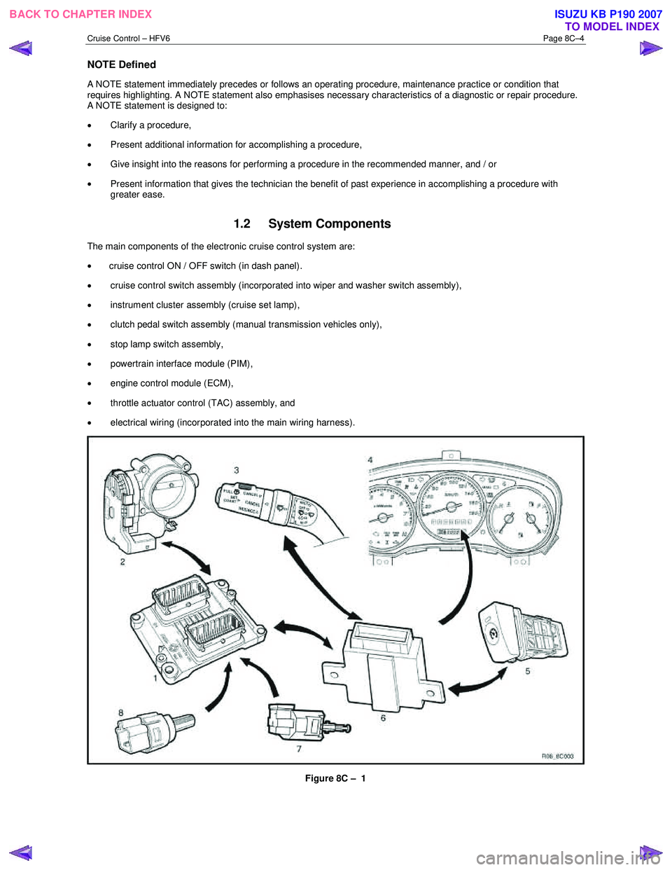
1.2 System Components
The main components of the electronic cruise control system are:
• cruise control ON / OFF switch (in dash panel).
• cruise control switch assembly (incorporated into wiper and washer switch assembly),
• instrument cluster assembly (cruise set lamp),
• clutch pedal switch assembly (manual transmission vehicles only),
• stop lamp switch assembly,
• powertrain interface module (PIM),
• engine control module (ECM),
• throttle actuator control (TAC) assembly, and
• electrical wiring (incorporated into the main wiring harness).
Figure 8C – 1
BACK TO CHAPTER INDEX TO MODEL INDEXISUZU KB P190 2007
Page 5597 of 6020
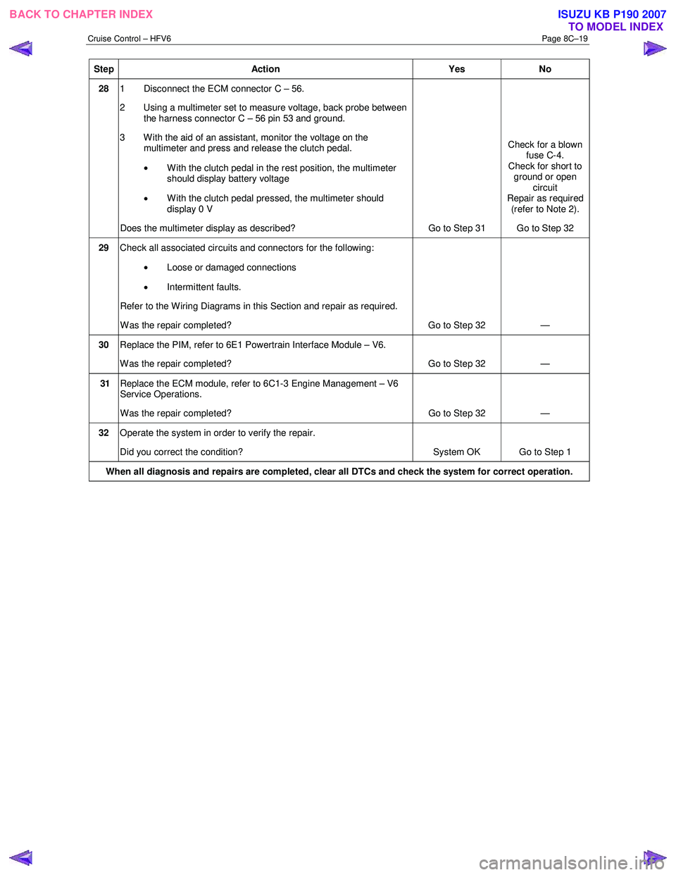
Cruise Control – HFV6 Page 8C–19
Step Action Yes No
28 1 Disconnect the ECM connector C – 56.
2 Using a multimeter set to measure voltage, back probe between the harness connector C – 56 pin 53 and ground.
3 W ith the aid of an assistant, monitor the voltage on the multimeter and press and release the clutch pedal.
• With the clutch pedal in the rest position, the multimeter
should display battery voltage
• W ith the clutch pedal pressed, the multimeter should
display 0 V
Does the multimeter display as described? Go to Step 31 Check for a blown
fuse C-4.
Check for short to ground or open circuit
Repair as required (refer to Note 2).
Go to Step 32
29 Check all associated circuits and connectors for the following:
• Loose or damaged connections
• Intermittent faults.
Refer to the Wiring Diagrams in this Section and repair as required.
W as the repair completed? Go to Step 32 —
30 Replace the PIM, refer to 6E1 Powertrain Interface Module – V6.
W as the repair completed? Go to Step 32 —
31 Replace the ECM module, refer to 6C1-3 Engine Management – V6
Service Operations.
W as the repair completed? Go to Step 32 —
32 Operate the system in order to verify the repair.
Did you correct the condition? System OK Go to Step 1
When all diagnosis and repairs are completed, clear all DTCs and check the system for correct operation.
BACK TO CHAPTER INDEX
TO MODEL INDEXISUZU KB P190 2007
Page 5639 of 6020
9A-4 SUPPLEMENTAL RESTRAINT SYSTEM
Service Precaution
WARNING: THIS VEHICLE HAS A SUPPLEMENTAL
RESTRAINT SYSTEM (SRS). REFER TO THE SRS
COMPONENT AND WIRING LOCATION VIEW IN
ORDER TO DETERMINE WHETHER YOU ARE
PERFORMING A SERVICE ON, OR NEAR, THE SRS
COMPONENTS OR THE SRS WIRING. WHEN YOU
ARE PERFORMING A SERVICE ON OR NEAR THE
SRS COMPONENTS OR THE SRS WIRING, REFER
TO THE SRS SERVICE INFORMATION. FAILURE
TO FOLLOW WARNINGS COULD RESULT IN
POSSIBLE AIR BAG DEPLOYMENT, PERSONAL
INJURY, OR OTHERWISE UNNECESSARY SRS
SYSTEM REPAIRS.
CAUTION: Always use the correct fastener in the
proper location. When you replace a fastener, use
ONLY the exact part number for that application.
ISUZU/GM will call out those fasteners that require
a replacement after removal. ISUZU/GM will also
call out the fasteners that require thread lockers o
r
thread sealant. UNLESS OTHERWISE SPECIFIED,
do not use supplemental coatings (paints,
greases, or other corrosion inhibitors) on threaded
fasteners or fastener joint interfaces. Generally,
such coatings adversely affect the fastener torque
and the joint clamping force, and may damage the
fastener. When you install fasteners, use the
correct tightening sequence and specifications.
Following these instructions can help you avoid
damage to parts and systems.
General Description
CAUTION: When fasteners are removed, always
reinstall them at the same location from which
they were removed. If a fastener needs to be
replaced, use the correct part number fastener fo
r
that application. If the correct part numbe
r
fastener is not available, a fastener of equal size
and strength (or stronger) may be used.
Fasteners that are not reused, and those requiring
thread locking compound will be called out. The
correct torque value must be used when installing
fasteners that require it. If the above conditions
are not followed, parts or system damage could
result.
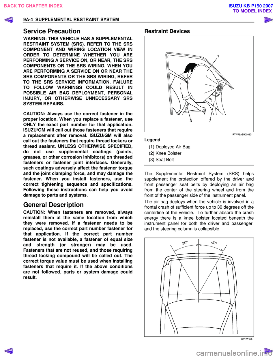
Restraint Devices
RTW 79ASH000801
Legend
(1) Deployed Air Bag
(2) Knee Bolster
(3) Seat Belt
The Supplemental Restraint System (SRS) helps
supplement the protection offered by the driver and
front passenger seat belts by deploying an air bag
from the center of the steering wheel and from the
front of the passenger side of the instrument panel.
The air bag deploys when the vehicle is involved in a
frontal crash of sufficient force up to 30 degrees off the
centerline of the vehicle. To further absorb the crash
energy there is a knee bolster located beneath the
instrument panel for both the driver and passenger,
and the steering column is collapsible.
827RW 005
BACK TO CHAPTER INDEX TO MODEL INDEXISUZU KB P190 2007