2007 ISUZU KB P190 air condition
[x] Cancel search: air conditionPage 4763 of 6020
7B1-44 Manual Transmission (MUX)
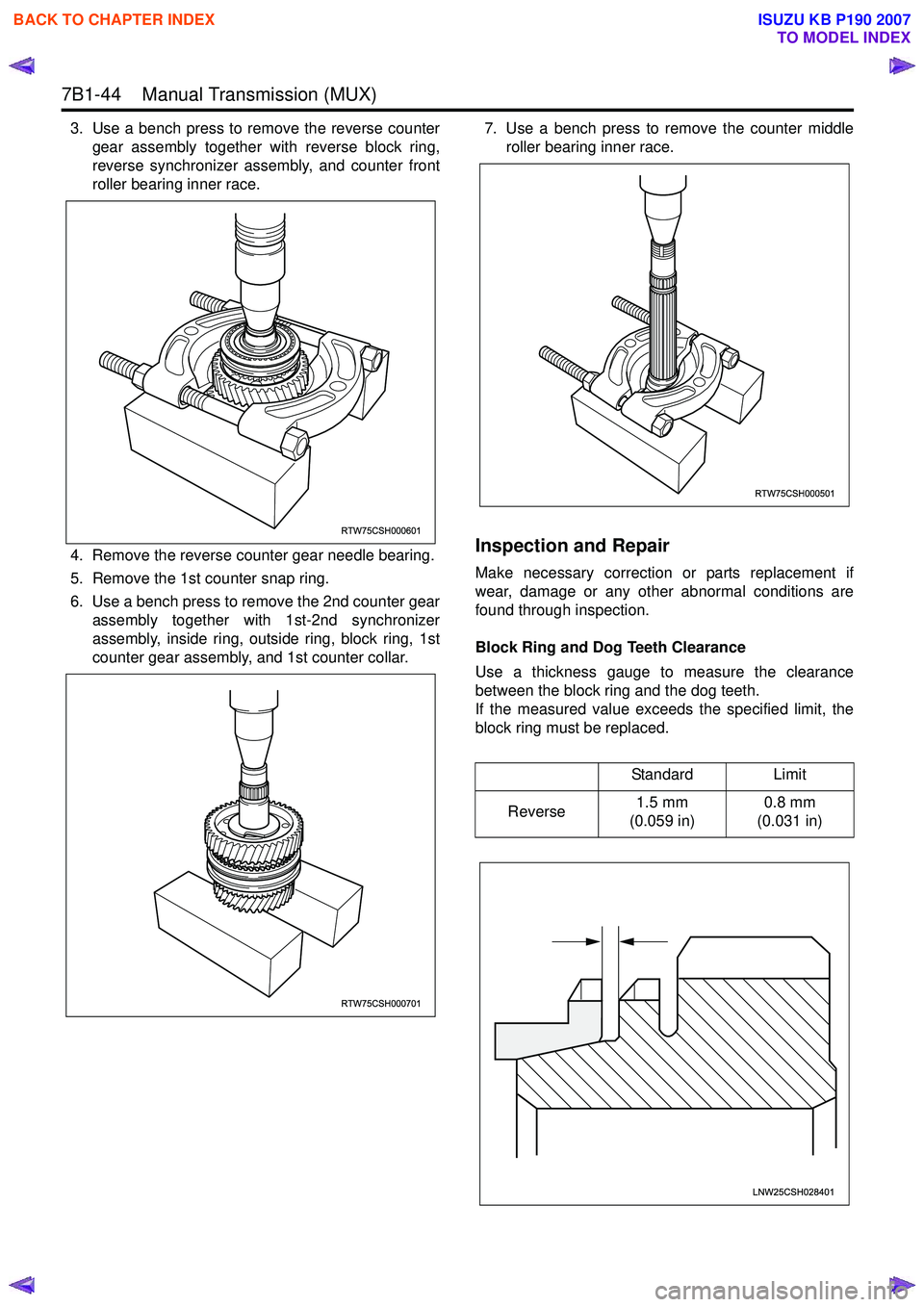
3. Use a bench press to remove the reverse countergear assembly together with reverse block ring,
reverse synchronizer assembly, and counter front
roller bearing inner race.
4. Remove the reverse counter gear needle bearing.
5. Remove the 1st counter snap ring.
6. Use a bench press to remove the 2nd counter gear assembly together with 1st-2nd synchronizer
assembly, inside ring, outside ring, block ring, 1st
counter gear assembly, and 1st counter collar. 7. Use a bench press to remove the counter middle
roller bearing inner race.
Inspection and Repair
Make necessary correction or parts replacement if
wear, damage or any other abnormal conditions are
found through inspection.
Block Ring and Dog Teeth Clearance
Use a thickness gauge to measure the clearance
between the block ring and the dog teeth.
If the measured value exceeds the specified limit, the
block ring must be replaced.
RTW75CSH000601
RTW75CSH000701
Standard Limit
Reverse 1.5 mm
(0.059 in) 0.8 mm
(0.031 in)
RTW75CSH000501
LNW25CSH028401
BACK TO CHAPTER INDEX
TO MODEL INDEX
ISUZU KB P190 2007
Page 4804 of 6020
7C-26 CLUTCH
INSPECTION AND REPAIR
Make the necessary adjustments, repairs, and part replacements if excessive wear or damage is discovered during
inspection.
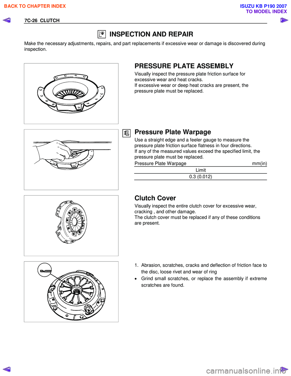
PRESSURE PLATE ASSEMBLY
Visually inspect the pressure plate friction surface for
excessive wear and heat cracks.
If excessive wear or deep heat cracks are present, the
pressure plate must be replaced.
Pressure Plate Warpage
Use a straight edge and a feeler gauge to measure the
pressure plate friction surface flatness in four directions.
If any of the measured values exceed the specified limit, the
pressure plate must be replaced.
Pressure Plate W arpage mm(in)
Limit
0.3 (0.012)
Clutch Cover
Visually inspect the entire clutch cover for excessive wear,
cracking , and other damage.
The clutch cover must be replaced if any of these conditions
are present.
1. Abrasion, scratches, cracks and deflection of friction face to
the disc, loose rivet and wear of ring
• Grind small scratches, or replace the assembly if extreme
scratches are found.
BACK TO CHAPTER INDEX
TO MODEL INDEX
ISUZU KB P190 2007
Page 4817 of 6020
CLUTCH 7C-39
INSPECTION AND REPAIR
Make the necessary adjustments, repairs, and part replacements if excessive wear or damage is discovered during
inspection.
RTW 77CSH000901
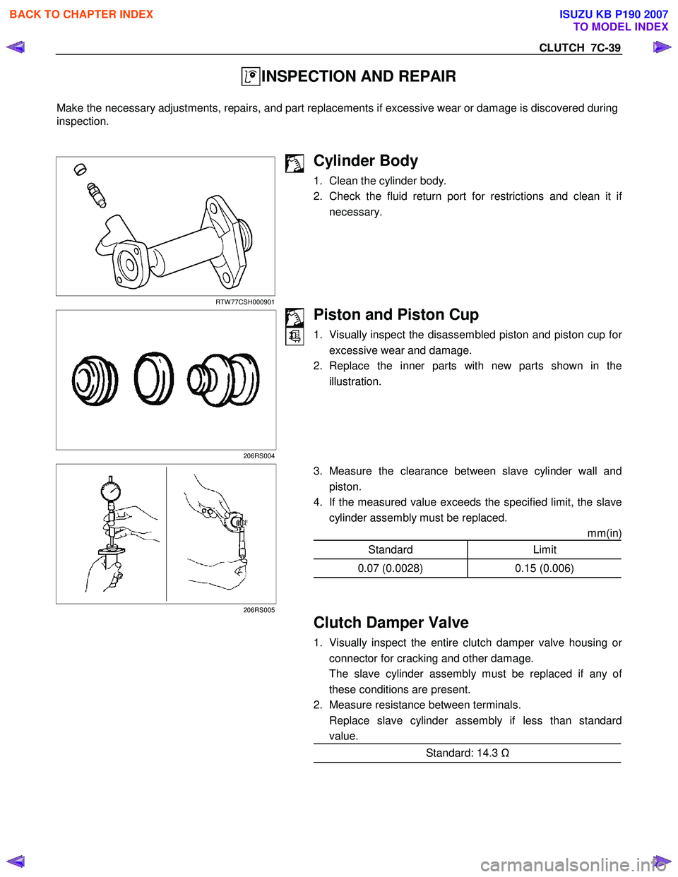
Cylinder Body
1. Clean the cylinder body.
2. Check the fluid return port for restrictions and clean it i
f
necessary.
206RS004
Piston and Piston Cup
1. Visually inspect the disassembled piston and piston cup for
excessive wear and damage.
2. Replace the inner parts with new parts shown in the illustration.
206RS005
3. Measure the clearance between slave cylinder wall and
piston.
4. If the measured value exceeds the specified limit, the slave cylinder assembly must be replaced.
mm(in)
Standard Limit
0.07 (0.0028) 0.15 (0.006)
Clutch Damper Valve
1. Visually inspect the entire clutch damper valve housing or
connector for cracking and other damage.
The slave cylinder assembly must be replaced if any o
f
these conditions are present.
2. Measure resistance between terminals.
Replace slave cylinder assembly if less than standard value.
Standard: 14.3 Ω
BACK TO CHAPTER INDEX
TO MODEL INDEX
ISUZU KB P190 2007
Page 4857 of 6020
TRANSFER CASE 7D-27
Inspection and Repair
1. Make the necessary repair or parts replacement if
wear, damage or any other abnormal conditions are
found during inspection.
2. W ash all parts thoroughly in clean solvent. Be sure all
old lubricant, metallic particles, dirt, or foreign material
are removed from the surfaces of every part. Appl
y
compressed air to each oil feed port and channel in
each case half to remove any obstructions or cleaning
solvent residue.
Inspection and Repair (Transfer Case
Assembly)
W hen wear, damage, or any other defects are observed
during the inspection, the part or parts must be repaired
or replaced. W ash all the parts with clean detergent, and
check that old oil, metallic particles, dirt, or foreign
materials are completely removed. Blow the air into oil
holes and grooves to remove foreign materials or
residual detergent.
Chain
• Check whether the face that contacts the sprocket is
free from excessive wear or damage. If defects are
observed, replace the part.
• If the chain interference mark is found on the inside
wall of the transfer cover or the chain is so slack that a
skipped engagement occurs between the chain and
sprocket, replace the chain.
Sprocket
• Check whether the sprocket tooth surface is
excessively worn or damaged, and there is evidence
of burrs, chipping, wear, or damage on the gear
spline. Remove minor flaws or scratches with oil
stone. If excessive wear or damage is observed,
replace the part.
• If excessive wear or damage is observed on the
sprocket inside sliding surface, replace the part.
Gear
• Check whether the gear tooth surface is excessively
worn or damaged, and there is evidence of burrs,
chipping, wear, or damage on the gear spline.
• Remove minor flaws or scratches with oil stone. I
f
excessive wear or damage is observed, replace the
part.
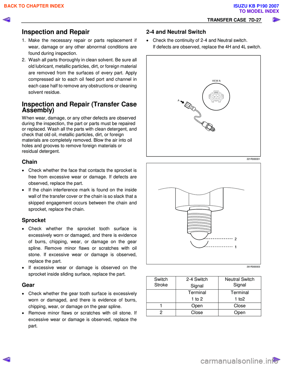
2-4 and Neutral Switch
• Check the continuity of 2-4 and Neutral switch.
If defects are observed, replace the 4H and 4L switch.
221R300001
261R300003
Switch
Stroke 2-4 Switch
Signal Neutral Switch
Signal
Terminal
1 to 2 Terminal
1 to2
1 Open Close
2 Close Open
BACK TO CHAPTER INDEX
TO MODEL INDEX
ISUZU KB P190 2007
Page 4858 of 6020
7D-28 TRANSFER CASE
Oil Pump
• Remove foreign materials from the strainer. If the
strainer is damaged, replace it.
If the area into which the shaft is inserted is excessively
worn or damaged, replace the oil pump assembly.
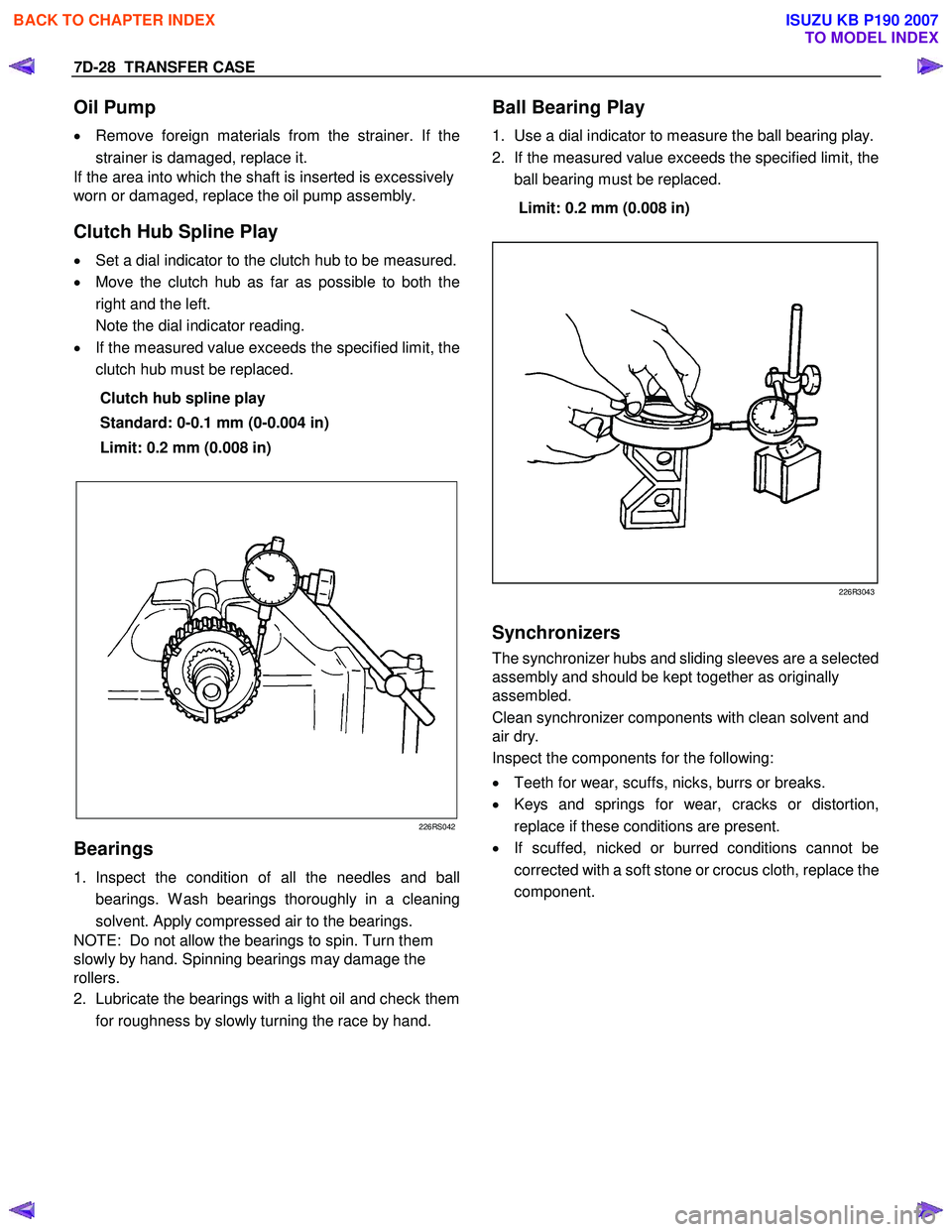
Clutch Hub Spline Play
• Set a dial indicator to the clutch hub to be measured.
• Move the clutch hub as far as possible to both the
right and the left.
Note the dial indicator reading.
• If the measured value exceeds the specified limit, the
clutch hub must be replaced.
Clutch hub spline play
Standard: 0-0.1 mm (0-0.004 in)
Limit: 0.2 mm (0.008 in)
226RS042
Bearings
1. Inspect the condition of all the needles and ball
bearings. W ash bearings thoroughly in a cleaning
solvent. Apply compressed air to the bearings.
NOTE: Do not allow the bearings to spin. Turn them
slowly by hand. Spinning bearings may damage the
rollers.
2. Lubricate the bearings with a light oil and check them
for roughness by slowly turning the race by hand.
Ball Bearing Play
1. Use a dial indicator to measure the ball bearing play.
2. If the measured value exceeds the specified limit, the
ball bearing must be replaced.
Limit: 0.2 mm (0.008 in)
226R3043
Synchronizers
The synchronizer hubs and sliding sleeves are a selected
assembly and should be kept together as originally
assembled.
Clean synchronizer components with clean solvent and
air dry.
Inspect the components for the following:
• Teeth for wear, scuffs, nicks, burrs or breaks.
• Keys and springs for wear, cracks or distortion,
replace if these conditions are present.
• If scuffed, nicked or burred conditions cannot be
corrected with a soft stone or crocus cloth, replace the
component.
BACK TO CHAPTER INDEX
TO MODEL INDEX
ISUZU KB P190 2007
Page 4928 of 6020
7D1-54 TRANSFER CONTROL SYSTEM
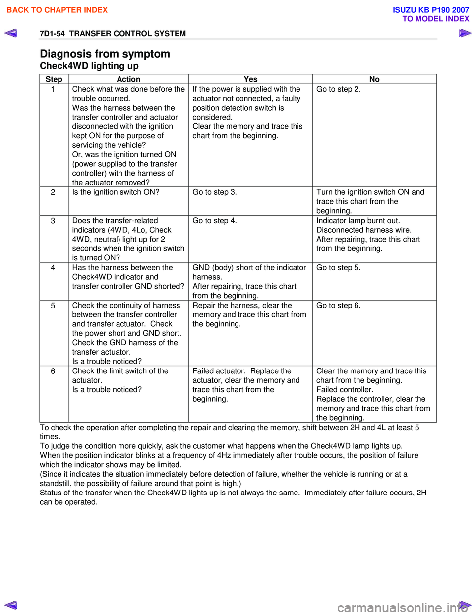
Diagnosis from symptom
Check4WD lighting up
Step Action Yes No
1 Check what was done before the
trouble occurred.
W as the harness between the
transfer controller and actuator
disconnected with the ignition
kept ON for the purpose of
servicing the vehicle?
Or, was the ignition turned ON
(power supplied to the transfer
controller) with the harness of
the actuator removed? If the power is supplied with the
actuator not connected, a faulty
position detection switch is
considered.
Clear the memory and trace this
chart from the beginning. Go to step 2.
2
Is the ignition switch ON? Go to step 3.
Turn the ignition switch ON and
trace this chart from the
beginning.
3 Does the transfer-related
indicators (4W D, 4Lo, Check
4W D, neutral) light up for 2
seconds when the ignition switch
is turned ON? Go to step 4.
Indicator lamp burnt out.
Disconnected harness wire.
After repairing, trace this chart
from the beginning.
4 Has the harness between the
Check4W D indicator and
transfer controller GND shorted? GND (body) short of the indicator
harness.
After repairing, trace this chart
from the beginning. Go to step 5.
5
Check the continuity of harness
between the transfer controller
and transfer actuator. Check
the power short and GND short.
Check the GND harness of the
transfer actuator.
Is a trouble noticed? Repair the harness, clear the
memory and trace this chart from
the beginning. Go to step 6.
6
Check the limit switch of the
actuator.
Is a trouble noticed? Failed actuator. Replace the
actuator, clear the memory and
trace this chart from the
beginning. Clear the memory and trace this
chart from the beginning.
Failed controller.
Replace the controller, clear the
memory and trace this chart from
the beginning.
To check the operation after completing the repair and clearing the memory, shift between 2H and 4L at least 5
times.
To judge the condition more quickly, ask the customer what happens when the Check4W D lamp lights up.
W hen the position indicator blinks at a frequency of 4Hz immediately after trouble occurs, the position of failure
which the indicator shows may be limited.
(Since it indicates the situation immediately before detection of failure, whether the vehicle is running or at a
standstill, the possibility of failure around that point is high.)
Status of the transfer when the Check4W D lights up is not always the same. Immediately after failure occurs, 2H
can be operated.
BACK TO CHAPTER INDEX
TO MODEL INDEX
ISUZU KB P190 2007
Page 4931 of 6020
TRANSFER CONTROL SYSTEM 7D1-57
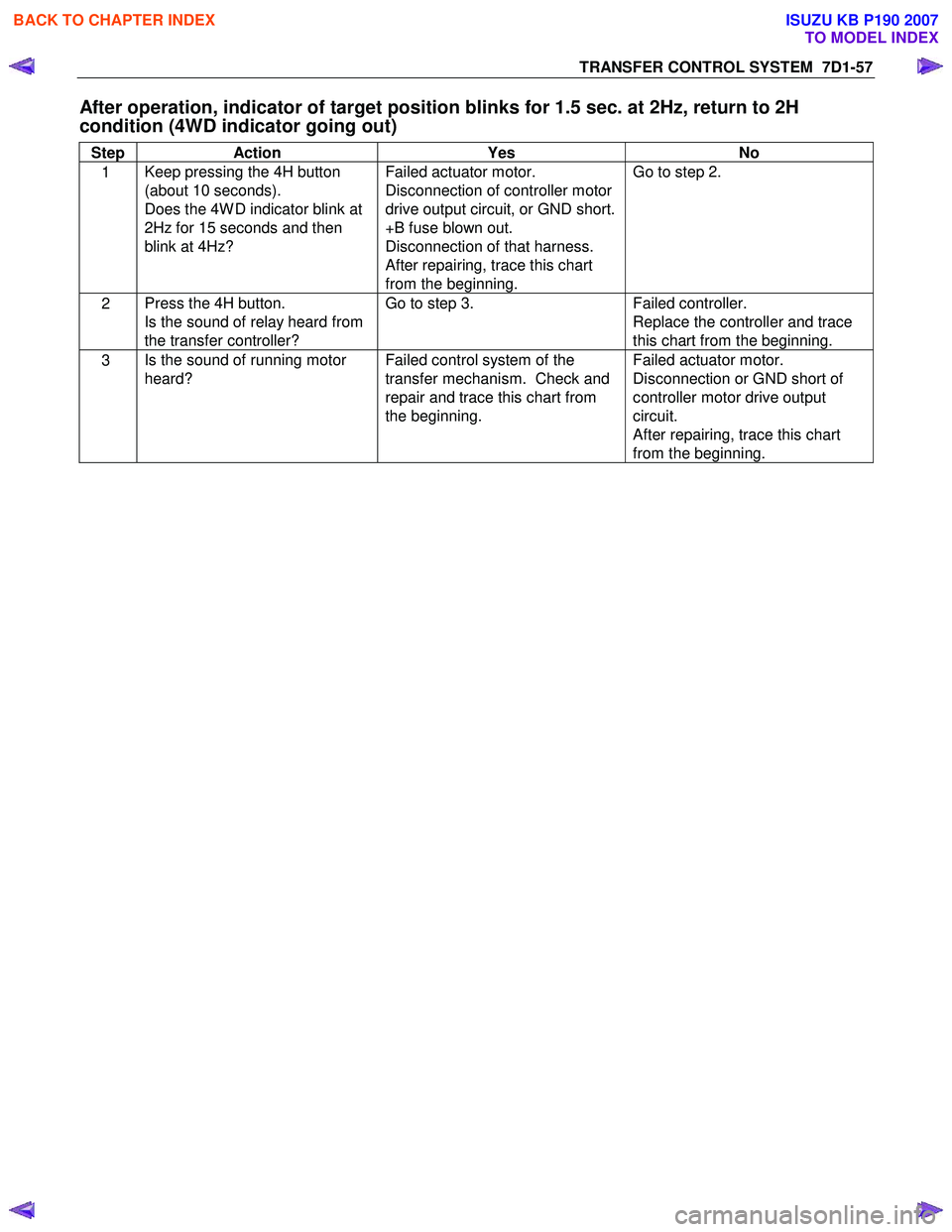
After operation, indicator of target position blinks for 1.5 sec. at 2Hz, return to 2H
condition (4WD indicator going out)
Step Action Yes No
1 Keep pressing the 4H button
(about 10 seconds).
Does the 4W D indicator blink at
2Hz for 15 seconds and then
blink at 4Hz? Failed actuator motor.
Disconnection of controller motor
drive output circuit, or GND short.
+B fuse blown out.
Disconnection of that harness.
After repairing, trace this chart
from the beginning. Go to step 2.
2
Press the 4H button.
Is the sound of relay heard from
the transfer controller? Go to step 3.
Failed controller.
Replace the controller and trace
this chart from the beginning.
3 Is the sound of running motor
heard? Failed control system of the
transfer mechanism. Check and
repair and trace this chart from
the beginning. Failed actuator motor.
Disconnection or GND short of
controller motor drive output
circuit.
After repairing, trace this chart
from the beginning.
BACK TO CHAPTER INDEX
TO MODEL INDEX
ISUZU KB P190 2007
Page 4932 of 6020
7D1-58 TRANSFER CONTROL SYSTEM
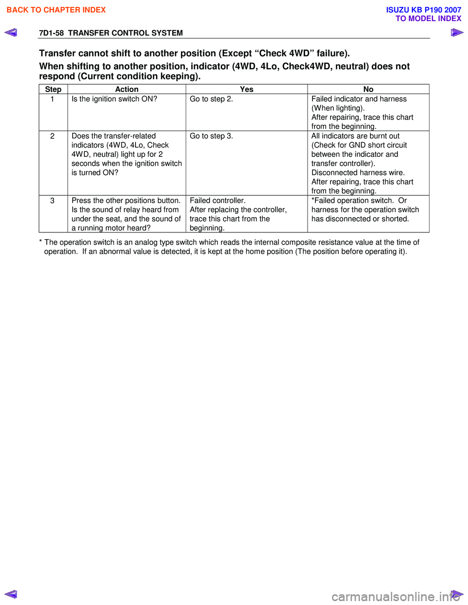
Transfer cannot shift to another position (Except “Check 4WD” failure).
When shifting to another position, indicator (4WD, 4Lo, Check4WD, neutral) does not
respond (Current condition keeping).
Step Action Yes No
1 Is the ignition switch ON? Go to step 2.
Failed indicator and harness
(W hen lighting).
After repairing, trace this chart
from the beginning.
2 Does the transfer-related
indicators (4W D, 4Lo, Check
4W D, neutral) light up for 2
seconds when the ignition switch
is turned ON? Go to step 3.
All indicators are burnt out
(Check for GND short circuit
between the indicator and
transfer controller).
Disconnected harness wire.
After repairing, trace this chart
from the beginning.
3 Press the other positions button.
Is the sound of relay heard from
under the seat, and the sound of
a running motor heard? Failed controller.
After replacing the controller,
trace this chart from the
beginning. *Failed operation switch. Or
harness for the operation switch
has disconnected or shorted.
* The operation switch is an analog type switch which reads the internal composite resistance value at the time of operation. If an abnormal value is detected, it is kept at the home position (The position before operating it).
BACK TO CHAPTER INDEX
TO MODEL INDEX
ISUZU KB P190 2007