2007 ISUZU KB P190 air condition
[x] Cancel search: air conditionPage 4312 of 6020
7A2-28 TRANSMISSION CONTROL SYSTEM (JR405E)
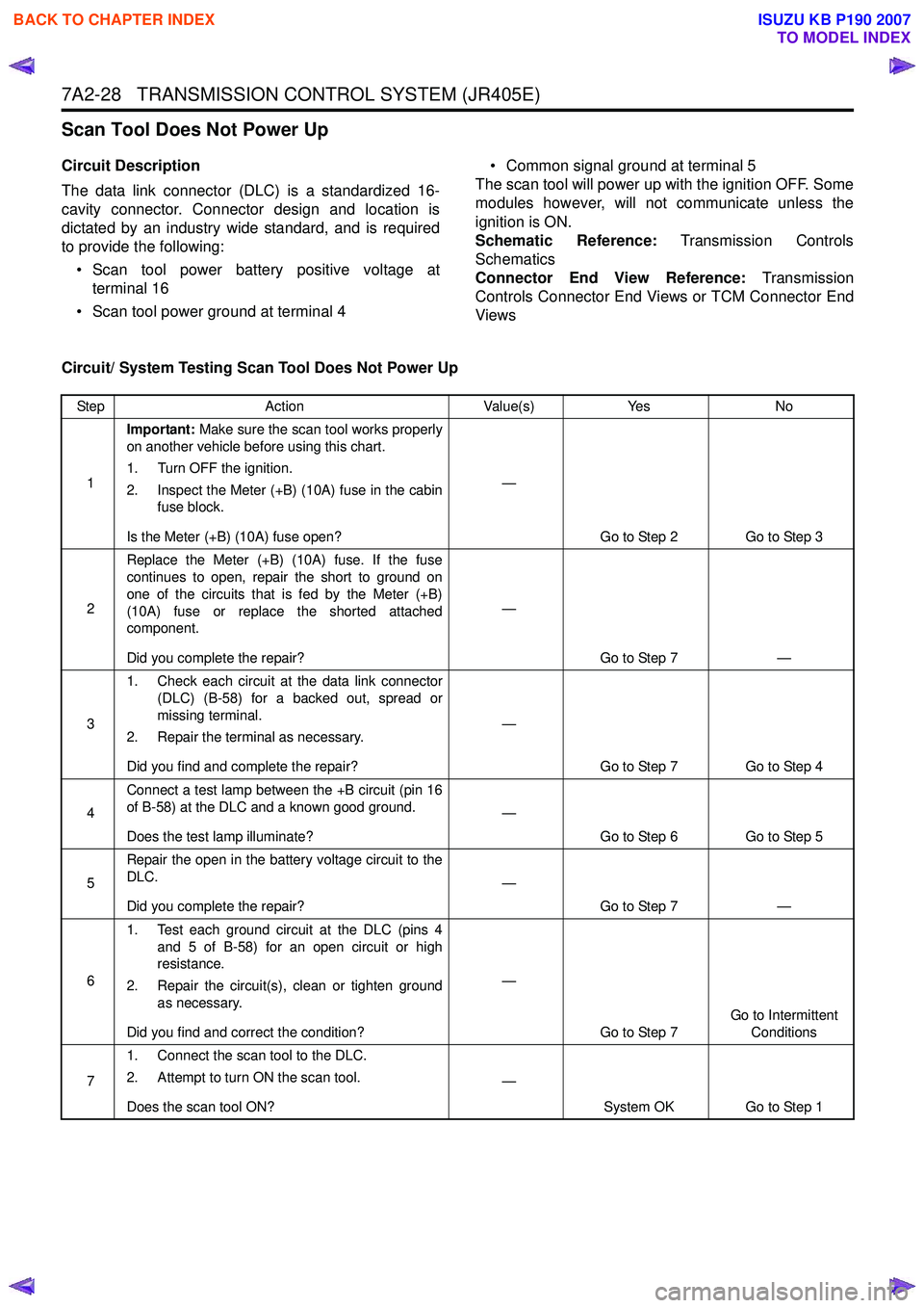
Scan Tool Does Not Power Up
Circuit Description
The data link connector (DLC) is a standardized 16-
cavity connector. Connector design and location is
dictated by an industry wide standard, and is required
to provide the following:
• Scan tool power battery positive voltage at terminal 16
• Scan tool power ground at terminal 4 • Common signal ground at terminal 5
The scan tool will power up with the ignition OFF. Some
modules however, will not communicate unless the
ignition is ON.
Schematic Reference: Transmission Controls
Schematics
Connector End View Reference: Transmission
Controls Connector End Views or TCM Connector End
Views
Circuit/ System Testing Scan Tool Does Not Power Up
Step Action Value(s)Yes No
1 Important:
Make sure the scan tool works properly
on another vehicle before using this chart.
1. Turn OFF the ignition.
2. Inspect the Meter (+B) (10A) fuse in the cabin fuse block.
Is the Meter (+B) (10A) fuse open? —
Go to Step 2 Go to Step 3
2 Replace the Meter (+B) (10A) fuse. If the fuse
continues to open, repair the short to ground on
one of the circuits that is fed by the Meter (+B)
(10A) fuse or replace the shorted attached
component.
Did you complete the repair? —
Go to Step 7 —
3 1. Check each circuit at the data link connector
(DLC) (B-58) for a backed out, spread or
missing terminal.
2. Repair the terminal as necessary.
Did you find and complete the repair? —
Go to Step 7 Go to Step 4
4 Connect a test lamp between the +B circuit (pin 16
of B-58) at the DLC and a known good ground.
Does the test lamp illuminate? —
Go to Step 6 Go to Step 5
5 Repair the open in the battery voltage circuit to the
DLC.
Did you complete the repair? —
Go to Step 7 —
6 1. Test each ground circuit at the DLC (pins 4
and 5 of B-58) for an open circuit or high
resistance.
2. Repair the circuit(s), clean or tighten ground as necessary.
Did you find and correct the condition? —
Go to Step 7 Go to Intermittent
Conditions
7 1. Connect the scan tool to the DLC.
2. Attempt to turn ON the scan tool.
Does the scan tool ON? —
System OK Go to Step 1
BACK TO CHAPTER INDEX
TO MODEL INDEX
ISUZU KB P190 2007
Page 4313 of 6020
![ISUZU KB P190 2007 Workshop Repair Manual TRANSMISSION CONTROL SYSTEM (JR405E) 7A2-29
Scan Tool Does Not Communicate with Keyword Device
Circuit Description
The TCM, electronic hydraulic control unit (EHCU)
[ABS module] and supplemental r ISUZU KB P190 2007 Workshop Repair Manual TRANSMISSION CONTROL SYSTEM (JR405E) 7A2-29
Scan Tool Does Not Communicate with Keyword Device
Circuit Description
The TCM, electronic hydraulic control unit (EHCU)
[ABS module] and supplemental r](/manual-img/61/57177/w960_57177-4312.png)
TRANSMISSION CONTROL SYSTEM (JR405E) 7A2-29
Scan Tool Does Not Communicate with Keyword Device
Circuit Description
The TCM, electronic hydraulic control unit (EHCU)
[ABS module] and supplemental restraint system
(SRS) control module all communicate with the scan
tool over the Keyword serial data link.
Diagnostic Aids
The following conditions will cause a loss of Keyword
serial data communication between the scan tool and
the TCM.
• A Keyword serial data circuit open • A Keyword serial data circuit shorted to ground
• A Keyword serial data circuit shorted to voltage
• An internal condition within a module or connector on the Keyword serial data circuit, that causes a
short to voltage or ground to the Keyword serial
data circuit
Schematic Reference: Transmission Controls
Schematics
Connector End View Reference: Transmission
Controls Connector End Views or TCM Connector End
Views
Circuit/ System Testing Scan Tool Does Not Communicate with Keyward Device
Step Action Value(s)Yes No
1 Did you perform the Diagnostic System Check -
Engine Controls? —
Go to Step 2 Go to Diagnostic
System Check - Transmission Controls
2 1. Install a scan tool.
2. Turn ON the ignition, with the engine OFF.
3. Attempt to establish communication with the listed control modules.
•TCM
• Electronic hydraulic control unit (EHCU) [ABS module] (If so equipped)
• Supplemental restraint system (SRS) control module (If so equipped)
Does the scan tool communicate with any of the
listed control modules? —
Go to Step 3 Go to Step 7
3 Does the scan tool communicate with the TCM?
—Go to Step 4 Go to Lost
Communication with
The Transmission Control Module (TCM)
4 Notice:
If no ABS is installed, skip to Step 5.
Does the scan tool communicate with the EHCU? —
Go to Step 5 Go to Diagnostic
System Check - Anti-lock Brake Controls
5 Notice:
If no SRS is installed, skip to Step 6.
Does the scan tool communicate with the SRS
control module? —
Go to Step 6 Go to Diagnostic
System Check -SRS Controls
6 Test the Keyword serial data circuit for an
intermittently short to ground or intermittently short
to voltage. Then, test the Keyword serial data
circuit for an intermittently open (based on which
control module did not communicate) at the
connection in the circuit.
Did you find and correct the condition? —
Go to Step 15 System OK
7 1. Inspect for an intermittent, for a poor
connection and for corrosion at the data link
connector (DLC) (pin 7 of B-58).
2. Repair the connection(s) as necessary.
Did you find and correct the condition? —
Go to Step 15 Go to Step 8
BACK TO CHAPTER INDEX
TO MODEL INDEX
ISUZU KB P190 2007
Page 4315 of 6020
![ISUZU KB P190 2007 Workshop Repair Manual TRANSMISSION CONTROL SYSTEM (JR405E) 7A2-31
Lost Communication with The Transmission Control Module (TCM)
Circuit Description
The TCM, electronic hydraulic control unit (EHCU)
[ABS module] and sup ISUZU KB P190 2007 Workshop Repair Manual TRANSMISSION CONTROL SYSTEM (JR405E) 7A2-31
Lost Communication with The Transmission Control Module (TCM)
Circuit Description
The TCM, electronic hydraulic control unit (EHCU)
[ABS module] and sup](/manual-img/61/57177/w960_57177-4314.png)
TRANSMISSION CONTROL SYSTEM (JR405E) 7A2-31
Lost Communication with The Transmission Control Module (TCM)
Circuit Description
The TCM, electronic hydraulic control unit (EHCU)
[ABS module] and supplemental restraint system
(SRS) control module all communicate with the scan
tool over the Keyword serial data link. Schematic Reference:
Transmission Controls
Schematics
Connector End View Reference: Transmission
Controls Connector End Views or TCM Connector End
Views
Circuit/ System Testing Lost Communication with The Transmission Control Module (TCM)
Step Action ActionYes No
1 Did you perform the Diagnostic System Check -
Engine Controls? —
Go to Step 2 Go to Diagnostic
System Check - Transmission
Controls
2 Attempt to establish communication with the TCM.
Does the scan tool communicate with the TCM? —
Go to Intermittent
Conditions Go to Step 3
3 1. Inspect for an intermittent, for poor
connections and for corrosion at the TCM C-
94 and C-95 harness connectors.
2. Repair the connection(s) as necessary.
Did you find and correct the condition? —
Go to Step 9 Go to Step 4
4 1. Check the TCM (15A) in the cabin fuse block.
Replace and retest if open. If any fuse
continues to open, repair the short to ground
on each circuit fed by that fuse.
2. Turn OFF the ignition.
3. Disconnect the TCM C-95 harness connector.
4. Turn ON the ignition, with the engine OFF.
5. Connect a test lamp to ground and check for voltage at the ignition voltage supply circuit at
the TCM (pins 18 and 24 of C-95).
Does the test lamp illuminate? —
Go to Step 6 Go to Step 5
5 Repair the open in the ignition voltage circuit to the
TCM.
Did you complete the repair? —
Go to Step 9 —
6 1. Turn OFF the ignition.
2. Disconnect the TCM C-94 harness connector.
3. Inspect for an intermittent, for poor connections and corrosion at the harness
connector of the TCM (pin 5 of C-94).
4. Test the Keyword serial data circuit between the TCM (pin 5 of C-94) and the DLC (pin 7 of
B-58) for an open circuit or high resistance.
5. Repair the connection(s) or circuit(s) as necessary.
Did you find and correct the condition? —
Go to Step 9 Go to Step 7
7 1. Check TCM ground for corrosion and
tightness.
2. Clean or tighten grounds as necessary.
Did you find and correct the condition? —
Go to Step 9 Go to Step 8
BACK TO CHAPTER INDEX
TO MODEL INDEX
ISUZU KB P190 2007
Page 4317 of 6020
TRANSMISSION CONTROL SYSTEM (JR405E) 7A2-33
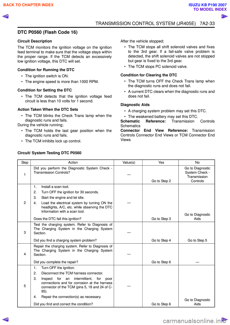
DTC P0560 (Flash Code 16)
Circuit Description
The TCM monitors the ignition voltage on the ignition
feed terminal to make sure that the voltage stays within
the proper range. If the TCM detects an excessively
low ignition voltage, this DTC will set.
Condition for Running the DTC • The ignition switch is ON.
• The engine speed is more than 1000 RPM.
Condition for Setting the DTC • The TCM detects that the ignition voltage feed circuit is less than 10 volts for 1 second.
Action Taken When the DTC Sets • The TCM blinks the Check Trans lamp when the diagnostic runs and fails.
During the vehicle running;
• The TCM holds the last gear position when the diagnostic runs and fails.
• The TCM inhibits lock up control. After the vehicle stopped;
• The TCM stops all shift solenoid valves and fixes to the 3rd gear. If a fail-safe valve problem is
detected, the shift solenoid valves are not stopped
but gear is fixed to the 3rd gear.
• The TCM stops PC solenoid valve.
Condition for Clearing the DTC • The TCM turns OFF the Check Trans lamp when the diagnostic runs and does not fail.
• A current DTC clears when the diagnostic runs and does not fail.
Diagnostic Aids • A charging system problem may set this DTC.
• The weakened battery may set this DTC.
Schematic Reference: Transmission Controls
Schematics
Connector End View Reference: Transmission
Controls Connector End Views or TCM Connector End
Views
Circuit/ System Testing DTC P0560
Step Action Value(s)Yes No
1 Did you perform the Diagnostic System Check -
Transmission Controls? —
Go to Step 2 Go to Diagnostic
System Check -
Transmission Controls
2 1. Install a scan tool.
2. Turn OFF the ignition for 30 seconds.
3. Start the engine and let idle.
4. Load the electrical system by turning ON the headlights, A/C, etc. while observing the DTC
Information with a scan tool.
Does the DTC fail this ignition? —
Go to Step 3 Go to Diagnostic
Aids
3 Test the charging system. Refer to Diagnosis of
The Charging System in the Charging System
Section.
Did you find a charging system problem? —
Go to Step 4 Go to Step 5
4 Repair the charging system. Refer to Diagnosis of
The Charging System in the Charging System
Section.
Did you complete the repair? —
Go to Step 6 —
5 1. Turn OFF the ignition.
2. Disconnect the TCM harness connector.
3. Inspect for an intermittent, for poor connections and for corrosion at the harness
connector of the TCM (pins 5, 18 and 24 of C-
95).
4. Repair the connection(s) as necessary.
Did you find and correct the condition? —
Go to Step 6 Go to Diagnostic
Aids
BACK TO CHAPTER INDEX
TO MODEL INDEX
ISUZU KB P190 2007
Page 4320 of 6020

7A2-36 TRANSMISSION CONTROL SYSTEM (JR405E)
DTC P0705 (Flash Code 17)
Circuit Description
The transmission range (TR) switch is connected to the
transmission manual shaft and installed externally to
the transmission case. The TR switch relays a signal to
the TCM indicating transmission range position by
detecting ignition voltage through an internal switch.
Only one of the seven internal switches will close for
each P, R, N, D, 3, 2 and L position. Normally, the TCM
expects to detect one high voltage input for each
position. If the TCM detects more than one high voltage
input at the same time or no input, this DTC will set.
Condition for Running the DTC • The ignition switch is ON.
Condition for Setting the DTC
Either of following condition is met: • The TCM detects that the TR switch signals are all OFF for 2 seconds when the engine speed is more
than 500 RPM.
• The TCM detects that multiple TR switch signals for 1 second.
Action Taken When the DTC Sets • The TCM blinks the Check Trans lamp when the diagnostic runs and fails. During the vehicle running;
• The TCM holds the last gear position when the diagnostic runs and fails.
• The TCM inhibits lock up control.
After the vehicle stopped;
• The TCM stops all shift solenoid valves and fixes to the 3rd gear. If a fail-safe valve problem is
detected, the shift solenoid valves are not stopped
but gear is fixed to the 3rd gear.
• The TCM stops PC solenoid valve.
Condition for Clearing the DTC • The TCM turns OFF the Check Trans lamp when the diagnostic runs and does not fail.
• A current DTC clears when the diagnostic runs and does not fail.
Diagnostic Aids • If an intermittent condition is suspected, refer to Intermittent Conditions in this section.
Schematic Reference: Transmission Controls
Schematics
Connector End View Reference: Transmission
Controls Connector End Views or TCM Connector End
Views
Circuit/ System Testing DTC P0705
Step Action Value(s)Yes No
1 Did you perform the Diagnostic System Check -
Transmission Controls? —
Go to Step 2 Go to Diagnostic
System Check - Transmission Controls
2 1. Install a scan tool.
2. Turn ON the ignition, with the engine OFF.
3. Observe the Transmission Range (TR) Switch P, R, N, D, 3, 2 and L parameter with a scan
tool while selecting each transmission range.
Does the scan tool indicate ON when its position
and OFF when other positions? —
Go to Diagnostic Aids Go to Step 3
3 1. Check to ensure the TR switch is adjusted
correctly.
2. Adjust the TR switch as necessary. Refer to repair instructions (On-Vehicle Service).
Did you find and correct the condition? —
Go to Step 16 Go to Step 4
4 1. Turn OFF the ignition.
2. Disconnect the TR switch harness connector.
3. Turn ON the ignition, with the engine OFF.
Does the scan tool indicate all TR Switch
parameters OFF? —
Go to Step 5 Go to Step 11
BACK TO CHAPTER INDEX
TO MODEL INDEX
ISUZU KB P190 2007
Page 4321 of 6020
TRANSMISSION CONTROL SYSTEM (JR405E) 7A2-37
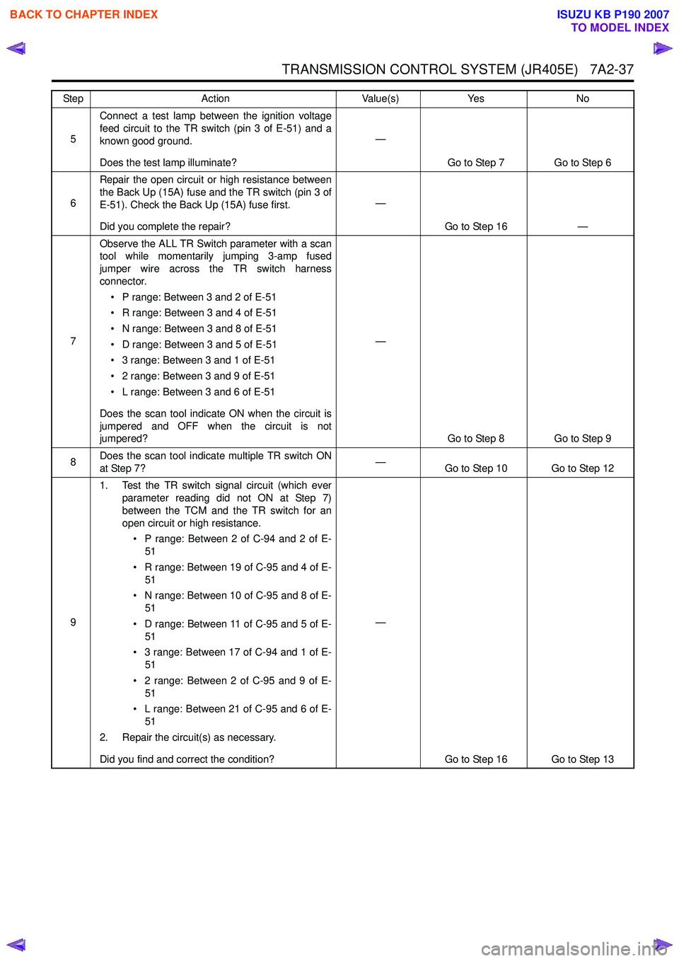
5Connect a test lamp between the ignition voltage
feed circuit to the TR switch (pin 3 of E-51) and a
known good ground.
Does the test lamp illuminate? —
Go to Step 7 Go to Step 6
6 Repair the open circuit or high resistance between
the Back Up (15A) fuse and the TR switch (pin 3 of
E-51). Check the Back Up (15A) fuse first.
Did you complete the repair? —
Go to Step 16 —
7 Observe the ALL TR Switch parameter with a scan
tool while momentarily jumping 3-amp fused
jumper wire across the TR switch harness
connector.
• P range: Between 3 and 2 of E-51
• R range: Between 3 and 4 of E-51
• N range: Between 3 and 8 of E-51
• D range: Between 3 and 5 of E-51
• 3 range: Between 3 and 1 of E-51
• 2 range: Between 3 and 9 of E-51
• L range: Between 3 and 6 of E-51
Does the scan tool indicate ON when the circuit is
jumpered and OFF when the circuit is not
jumpered? —
Go to Step 8 Go to Step 9
8 Does the scan tool indicate multiple TR switch ON
at Step 7? —
Go to Step 10 Go to Step 12
9 1. Test the TR switch signal circuit (which ever
parameter reading did not ON at Step 7)
between the TCM and the TR switch for an
open circuit or high resistance.
• P range: Between 2 of C-94 and 2 of E- 51
• R range: Between 19 of C-95 and 4 of E- 51
• N range: Between 10 of C-95 and 8 of E- 51
• D range: Between 11 of C-95 and 5 of E- 51
• 3 range: Between 17 of C-94 and 1 of E- 51
• 2 range: Between 2 of C-95 and 9 of E- 51
• L range: Between 21 of C-95 and 6 of E- 51
2. Repair the circuit(s) as necessary.
Did you find and correct the condition? —
Go to Step 16 Go to Step 13
Step
Action Value(s)Yes No
BACK TO CHAPTER INDEX
TO MODEL INDEX
ISUZU KB P190 2007
Page 4322 of 6020
7A2-38 TRANSMISSION CONTROL SYSTEM (JR405E)
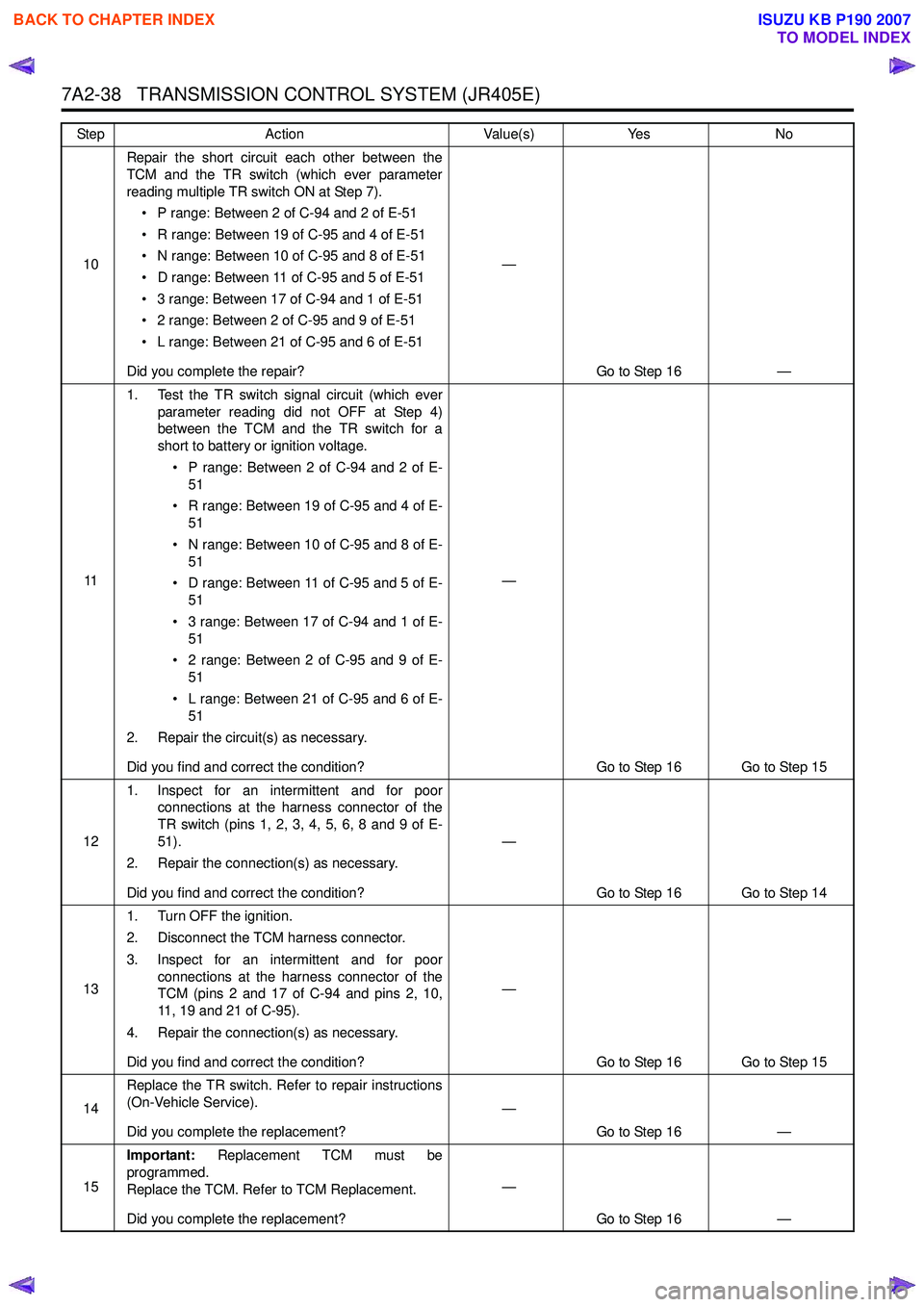
10Repair the short circuit each other between the
TCM and the TR switch (which ever parameter
reading multiple TR switch ON at Step 7).
• P range: Between 2 of C-94 and 2 of E-51
• R range: Between 19 of C-95 and 4 of E-51
• N range: Between 10 of C-95 and 8 of E-51
• D range: Between 11 of C-95 and 5 of E-51
• 3 range: Between 17 of C-94 and 1 of E-51
• 2 range: Between 2 of C-95 and 9 of E-51
• L range: Between 21 of C-95 and 6 of E-51
Did you complete the repair? —
Go to Step 16 —
11 1. Test the TR switch signal circuit (which ever
parameter reading did not OFF at Step 4)
between the TCM and the TR switch for a
short to battery or ignition voltage.
• P range: Between 2 of C-94 and 2 of E- 51
• R range: Between 19 of C-95 and 4 of E- 51
• N range: Between 10 of C-95 and 8 of E- 51
• D range: Between 11 of C-95 and 5 of E- 51
• 3 range: Between 17 of C-94 and 1 of E- 51
• 2 range: Between 2 of C-95 and 9 of E- 51
• L range: Between 21 of C-95 and 6 of E- 51
2. Repair the circuit(s) as necessary.
Did you find and correct the condition? —
Go to Step 16 Go to Step 15
12 1. Inspect for an intermittent and for poor
connections at the harness connector of the
TR switch (pins 1, 2, 3, 4, 5, 6, 8 and 9 of E-
51).
2. Repair the connection(s) as necessary.
Did you find and correct the condition? —
Go to Step 16 Go to Step 14
13 1. Turn OFF the ignition.
2. Disconnect the TCM harness connector.
3. Inspect for an intermittent and for poor connections at the harness connector of the
TCM (pins 2 and 17 of C-94 and pins 2, 10,
11, 19 and 21 of C-95).
4. Repair the connection(s) as necessary.
Did you find and correct the condition? —
Go to Step 16 Go to Step 15
14 Replace the TR switch. Refer to repair instructions
(On-Vehicle Service).
Did you complete the replacement? —
Go to Step 16 —
15 Important:
Replacement TCM must be
programmed.
Replace the TCM. Refer to TCM Replacement.
Did you complete the replacement? —
Go to Step 16 —
Step
Action Value(s)Yes No
BACK TO CHAPTER INDEX
TO MODEL INDEX
ISUZU KB P190 2007
Page 4325 of 6020
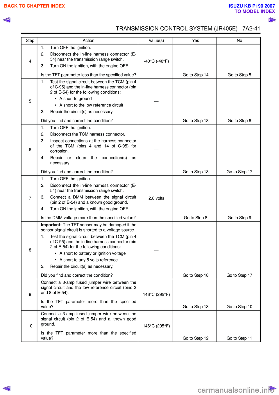
TRANSMISSION CONTROL SYSTEM (JR405E) 7A2-41
41. Turn OFF the ignition.
2. Disconnect the in-line harness connector (E- 54) near the transmission range switch.
3. Turn ON the ignition, with the engine OFF.
Is the TFT parameter less than the specified value? -40
°C (-40 °F)
Go to Step 14 Go to Step 5
5 1. Test the signal circuit between the TCM (pin 4
of C-95) and the in-line harness connector (pin
2 of E-54) for the following conditions:
• A short to ground
• A short to the low reference circuit
2. Repair the circuit(s) as necessary.
Did you find and correct the condition? —
Go to Step 18 Go to Step 6
6 1. Turn OFF the ignition.
2. Disconnect the TCM harness connector.
3. Inspect connections at the harness connector of the TCM (pins 4 and 14 of C-95) for
corrosion.
4. Repair or clean the connection(s) as necessary.
Did you find and correct the condition? —
Go to Step 18 Go to Step 17
7 1. Turn OFF the ignition.
2. Disconnect the in-line harness connector (E- 54) near the transmission range switch.
3. Connect a DMM between the signal circuit (pin 2 of E-54) and a known good ground.
4. Turn ON the ignition, with the engine OFF.
Is the DMM voltage more than the specified value? 2.8 volts
Go to Step 8 Go to Step 9
8 Important:
The TFT sensor may be damaged if the
sensor signal circuit is shorted to a voltage source.
1. Test the signal circuit between the TCM (pin 4 of C-95) and the in-line harness connector (pin
2 of E-54) for the following conditions:
• A short to battery or ignition voltage
• A short to any 5 volts reference
2. Repair the circuit(s) as necessary.
Did you find and correct the condition? —
Go to Step 18 Go to Step 17
9 Connect a 3-amp fused jumper wire between the
signal circuit and the low reference circuit (pins 2
and 8 of E-54).
Is the TFT parameter more than the specified
value? 146
°C (295 °F)
Go to Step 13 Go to Step 10
10 Connect a 3-amp fused jumper wire between the
signal circuit (pin 2 of E-54) and a known good
ground.
Is the TFT parameter more than the specified
value? 146
°C (295 °F)
Go to Step 12 Go to Step 11
Step
Action Value(s)Yes No
BACK TO CHAPTER INDEX
TO MODEL INDEX
ISUZU KB P190 2007