2007 ISUZU KB P190 air condition
[x] Cancel search: air conditionPage 4078 of 6020
7A2-112 TRANSMISSION CONTROL SYSTEM (AW30–40LE)
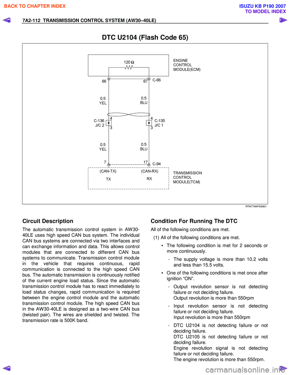
DTC U2104 (Flash Code 65)
RTW 77AMF000801
Circuit Description
The automatic transmission control system in AW 30-
40LE uses high speed CAN bus system. The individual
CAN bus systems are connected via two interfaces and
can exchange information and data. This allows control
modules that are connected to different CAN bus
systems to communicate. Transmission control module
in the vehicle that requires continuous, rapid
communication is connected to the high speed CAN
bus. The automatic transmission is continuously notified
of the current engine load status. Since the automatic
transmission control module has to react immediately to
load status changes, rapid communication is required
between the engine control module and the automatic
transmission control module. The high speed CAN bus
in the AW 30-40LE is designed as a two-wire CAN bus
(twisted pair). The wires are shielded and twisted. The
transmission rate is 500K band.
Condition For Running The DTC
All of the following conditions are met.
(1) All of the following conditions are met. • The following condition is met for 2 seconds o
r
more continuously.
- The supply voltage is more than 10.2 volts and less than 15.5 volts.
• One of the following conditions is met once afte
r
ignition “ON”.
- Output revolution sensor is not detecting failure or not deciding failure.
Output revolution is more than 550rpm
- Input revolution sensor is not detecting failure or not deciding failure.
Input revolution is more than 550rpm
- DTC U2104 is not detecting failure or not deciding failure.
DTC U2105 is not detecting failure or not
deciding failure.
Engine revolution signal is not detecting
failure or not deciding failure.
The engine revolution is more than 550rpm.
BACK TO CHAPTER INDEX
TO MODEL INDEX
ISUZU KB P190 2007
Page 4081 of 6020
TRANSMISSION CONTROL SYSTEM (AW30–40LE) 7A2-115
Step Action Value(s) YES NO
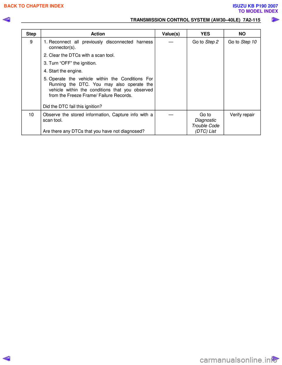
9 1. Reconnect all previously disconnected harness
connector(s).
2. Clear the DTCs with a scan tool.
3. Turn “OFF” the ignition.
4. Start the engine.
5. Operate the vehicle within the Conditions For Running the DTC. You may also operate the
vehicle within the conditions that you observed
from the Freeze Frame/ Failure Records.
Did the DTC fail this ignition? — Go to
Step 2 Go to Step 10
10 Observe the stored information, Capture info with a
scan tool.
Are there any DTCs that you have not diagnosed? — Go
to
Diagnostic
Trouble Code (DTC) List Verify repair
BACK TO CHAPTER INDEX
TO MODEL INDEX
ISUZU KB P190 2007
Page 4082 of 6020
7A2-116 TRANSMISSION CONTROL SYSTEM (AW30–40LE)
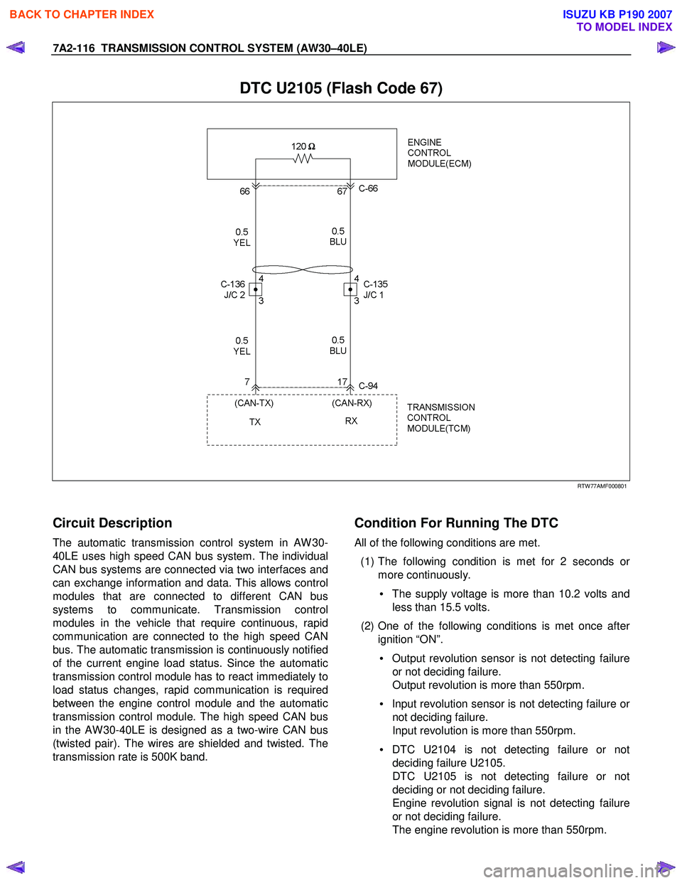
DTC U2105 (Flash Code 67)
RTW 77AMF000801
Circuit Description
The automatic transmission control system in AW 30-
40LE uses high speed CAN bus system. The individual
CAN bus systems are connected via two interfaces and
can exchange information and data. This allows control
modules that are connected to different CAN bus
systems to communicate. Transmission control
modules in the vehicle that require continuous, rapid
communication are connected to the high speed CAN
bus. The automatic transmission is continuously notified
of the current engine load status. Since the automatic
transmission control module has to react immediately to
load status changes, rapid communication is required
between the engine control module and the automatic
transmission control module. The high speed CAN bus
in the AW 30-40LE is designed as a two-wire CAN bus
(twisted pair). The wires are shielded and twisted. The
transmission rate is 500K band.
Condition For Running The DTC
All of the following conditions are met.
(1) The following condition is met for 2 seconds o
r
more continuously.
• The supply voltage is more than 10.2 volts and
less than 15.5 volts.
(2) One of the following conditions is met once afte
r
ignition “ON”.
• Output revolution sensor is not detecting failure
or not deciding failure.
Output revolution is more than 550rpm.
• Input revolution sensor is not detecting failure o
r
not deciding failure.
Input revolution is more than 550rpm.
• DTC U2104 is not detecting failure or not
deciding failure U2105.
DTC U2105 is not detecting failure or not
deciding or not deciding failure.
Engine revolution signal is not detecting failure
or not deciding failure.
The engine revolution is more than 550rpm.
BACK TO CHAPTER INDEX
TO MODEL INDEX
ISUZU KB P190 2007
Page 4085 of 6020
TRANSMISSION CONTROL SYSTEM (AW30–40LE) 7A2-119
Step Action Value(s) YES NO
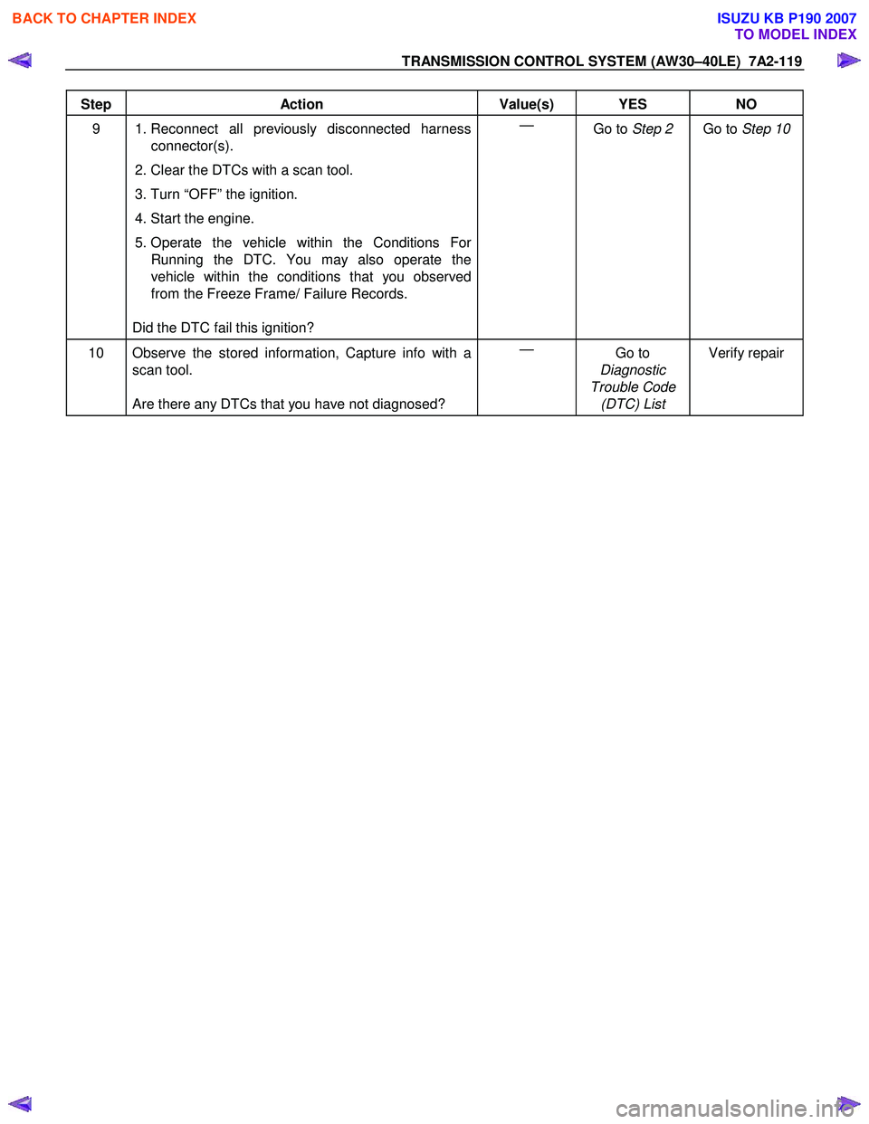
9 1. Reconnect all previously disconnected harness
connector(s).
2. Clear the DTCs with a scan tool.
3. Turn “OFF” the ignition.
4. Start the engine.
5. Operate the vehicle within the Conditions For Running the DTC. You may also operate the
vehicle within the conditions that you observed
from the Freeze Frame/ Failure Records.
Did the DTC fail this ignition? —
Go to Step 2 Go to Step 10
10 Observe the stored information, Capture info with a
scan tool.
Are there any DTCs that you have not diagnosed? —
Go to
Diagnostic
Trouble Code (DTC) List Verify repair
BACK TO CHAPTER INDEX
TO MODEL INDEX
ISUZU KB P190 2007
Page 4146 of 6020
UNIT REPAIR (AW30–40LE) 7A4–11
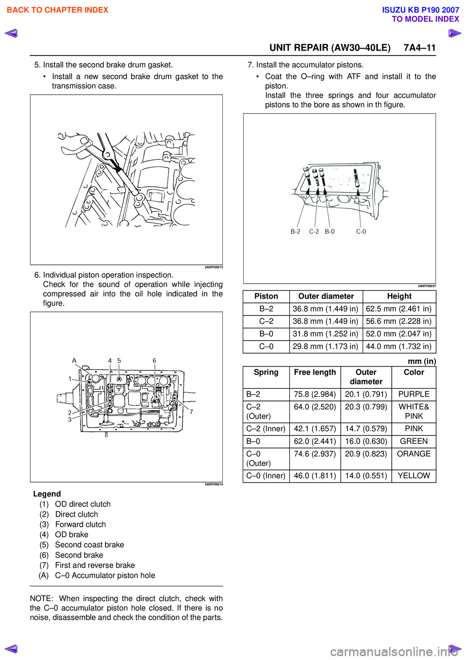
5. Install the second brake drum gasket. Install a new second brake drum gasket to the
transmission case.
240RY00013
6. Individual piston operation inspection. Check for the sound of operation while injecting
compressed air into the oil hole indicated in the
figure.
240RY00014
E ndOFCallout
NOTE: When inspecting the direct clutch, check with
the C –0 accumulator piston hole closed. If there is no
noise, disassemble and check the condition of the parts. 7. Install the accumulator pistons.
Coat the O –ring with ATF and install it to the
piston.
Install the three springs and four accumulator
pistons to the bore as shown in th figure.
240RY00027
mm (in)
Legend (1) OD direct clutch
(2) Direct clutch
(3) Forward clutch
(4) OD brake
(5) Second coast brake
(6) Second brake
(7) First and reverse brake
(A) C –0 Accumulator piston hole
Piston Outer diameter Height
B –2 36.8 mm (1.449 in) 62.5 mm (2.461 in)
C –2 36.8 mm (1.449 in) 56.6 mm (2.228 in)
B –0 31.8 mm (1.252 in) 52.0 mm (2.047 in)
C –0 29.8 mm (1.173 in) 44.0 mm (1.732 in)
Spring Free length Outer diameterColor
B –2 75.8 (2.984) 20.1 (0.791) PURPLE
C –2
(Outer) 64.0 (2.520) 20.3 (0.799) WHITE&
PINK
C –2 (Inner) 42.1 (1.657) 14.7 (0.579) PINK
B –0 62.0 (2.441) 16.0 (0.630) GREEN
C –0
(Outer) 74.6 (2.937) 20.9 (0.823) ORANGE
C –0 (Inner) 46.0 (1.811) 14.0 (0.551) YELLOW
BACK TO CHAPTER INDEX
TO MODEL INDEX
ISUZU KB P190 2007
Page 4173 of 6020
7A4–38 UNIT REPAIR (AW30–40LE)
2. Remove the O-ring.
3. Remove the stator shaft.
4. Remove the oil pump drive gear.
5. Remove the oil pump driven gear.
6. Remove the oil pump body. Remove 13 bolts, and then remove the stator shaft
from oil pump body.
Then remove drive and driven gear.
241RY00006
Inspection and Repair
Make necessary correction or parts replacement if wear,
damage or any abnormal conditions are found through
inspection.
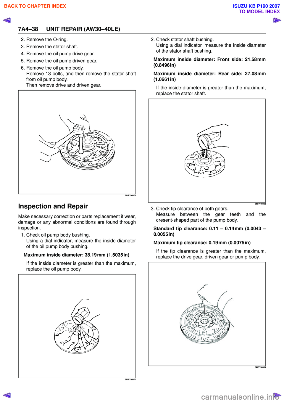
1. Check oil pump body bushing. Using a dial indicator, measure the inside diameter
of the oil pump body bushing.
Maximum inside diameter: 38.19 mm (1.5035 in) If the inside diameter is greater than the maximum,
replace the oil pump body.
241RY00007
2. Check stator shaft bushing. Using a dial indicator, measure the inside diameter
of the stator shaft bushing.
Maximum inside diameter: Front side: 21.58 mm
(0.8496 in)
Maximum inside diameter: Rear side: 27.08 mm
(1.0661 in)
If the inside diameter is greater than the maximum,
replace the stator shaft.
241RY00008
3. Check tip clearance of both gears. Measure between the gear teeth and the
cresent-shaped part of the pump body.
Standard tip clearance: 0.11 – 0.14 mm (0.0043 –
0.0055 in)
Maximum tip clearance: 0.19 mm (0.0075 in) If the tip clearance is greater than the maximum,
replace the drive gear, driven gear or pump body.
241RY00009
BACK TO CHAPTER INDEX
TO MODEL INDEX
ISUZU KB P190 2007
Page 4188 of 6020
UNIT REPAIR (AW30–40LE) 7A4–53
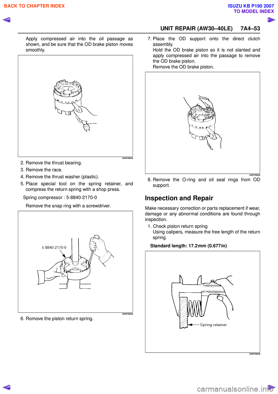
Apply compressed air into the oil passage as
shown, and be sure that the OD brake piston moves
smoothly.
252RY00043
2. Remove the thrust bearing.
3. Remove the race.
4. Remove the thrust washer (plastic).
5. Place special tool on the spring retainer, and compress the return spring with a shop press.
Spring compressor : 5-8840-2170-0 Remove the snap ring with a screwdriver.
252RY00044
6. Romove the piston return spring. 7. Place the OD support onto the direct clutch
assembly.
Hold the OD brake piston so it is not slanted and
apply compressed air into the passage to remove
the OD brake piston.
Remove the OD brake piston.
252RY00045
8. Remove the O-ring and oil seal rings from OD support.
Inspection and Repair
Make necessary correction or parts replacement if wear,
damage or any abnormal conditions are found through
inspection.
1. Check piston return spring Using calipers, measure the free length of the return
spring.
Standard length: 17.2 mm (0.677 in)
252RY00046
BACK TO CHAPTER INDEX
TO MODEL INDEX
ISUZU KB P190 2007
Page 4285 of 6020

TRANSMISSION CONTROL SYSTEM (JR405E) 7A2-1
TRANSMISSION
TRANSMISSION CONTROL SYSTEM (JR405E)
This manual conforms when Scan Tool of ISO CAN Base Software is used.
TABLE OF CONTENTS
Specifications ...................................................... 7A2-2Transmission General Specifications ............... 7A2-2
Transmission Fluid Temperature vs. Resistance..... 7A2-3
Clutch, Brake, Solenoid and Pressure Switch Logic........ 7A2-4
Diagnostic Trouble Code (DTC) List ................ 7A2-5
Schematic and Routing Diagrams....................... 7A2-6 Transmission Controls Schematics .................. 7A2-6
Component Locator........................................... 7A2-13 Transmission Controls Component Views ..... 7A2-13
Transmission Control Module (TCM) Connector End Views ................................... 7A2-17
Transmission Control Connector End Views.. 7A2-18
Diagnostic Information and Procedures ............ 7A2-21
Diagnostic Starting Point - Transmission Controls......... 7A2-21
Diagnostic System Check - Transmission Controls....... 7A2-22
Scan Tool Data List ........................................ 7A2-24
Scan Tool Data Definitions............................. 7A2-25
Scan Tool Output Controls ............................. 7A2-27
Scan Tool Does Not Power Up ...................... 7A2-28
Scan Tool Does Not Communicate with Keyword Device .................................... 7A2-29
Lost Communication with The Transmission Control Module (TCM)
.... 7A2-31
DTC P0560 (Flash Code 16).......................... 7A2-33
DTC P0602 .................................................... 7A2-35
DTC P0705 (Flash Code 17).......................... 7A2-36
DTC P0710 (Flash Code 15).......................... 7A2-40
DTC P0717 (Flash Code 14).......................... 7A2-44
DTC P0722 (Flash Code 11).......................... 7A2-47
DTC P0727 (Flash Code 13).......................... 7A2-50
DTC P0731, P0732, P0733 or P0734 (Flash Code 41, 42, 43 or 44)....................... 7A2-52
DTC P0748 (Flash Code 35).......................... 7A2-55
DTC P0753 (Flash Code 31).......................... 7A2-58
DTC P0758 (Flash Code 32).......................... 7A2-61
DTC P0763 (Flash Code 33).......................... 7A2-64
DTC P0768 (Flash Code 34).......................... 7A2-67
DTC P1120 (Flash Code 22).......................... 7A2-70
DTC P1750 (Flash Code 51).......................... 7A2-71
DTC P1755 (Flash Code 52).......................... 7A2-73
DTC P1853 (Flash Code 26).......................... 7A2-75
DTC P1858 (Flash Code 27).......................... 7A2-78
DTC P1860 (Flash Code 36).......................... 7A2-81
DTC P1863 (Flash Code 28).......................... 7A2-84
DTC P1875 (Flash Code 25).......................... 7A2-87
Check Trans Lamp Inoperative, Always On or Always Blinking ...................... 7A2-89
Symptoms - Transmission Controls .................. 7A2-92 Symptoms - Transmission Controls ............... 7A2-92
Intermittent Conditions ................................... 7A2-93 Vehicle Does Not Run .................................... 7A2-95
Trouble at Starting.......................................... 7A2-95
Faulty Gearshift .............................................. 7A2-95
Faulty Shift Pattern......................................... 7A2-95
No or Error Gearshift ...................................... 7A2-95
Faulty Operation During Running................... 7A2-95
Faulty Operation in Stopping.......................... 7A2-95
Faulty Lock Up ............................................... 7A2-95
No Lock Up .................................................... 7A2-95
Transmission Fluid Leak ................................ 7A2-95
Others ............................................................ 7A2-95
Test Instructions .............................................. 7A2-121 Line Pressure Test ....................................... 7A2-121
Stall Test ...................................................... 7A2-123
Time Lag Test .............................................. 7A2-124
Road Test..................................................... 7A2-125
TCM Signal Test .......................................... 7A2-134
Repair Instructions .......................................... 7A2-139
Transmission Controls Module (TCM) Replacement.... 7A2-139
Service Programming System (SPS) Description........ 7A2-139
Service Programming System (SPS) (Remote Procedure)......................... 7A2-140
Service Programming System (SPS) (Pass-Thru Procedure)..................... 7A2-141
Description and Operation .............................. 7A2-143 Transmission Identification Information........ 7A2-143
Transmission General Description ............... 7A2-143
Transmission Component Description ......... 7A2-144
Transmission Control System Description ... 7A2-152
Transmission Power Flow Description ......... 7A2-161
Special Tools and Equipment ......................... 7A2-170 Special Tools and Equipment ...................... 7A2-170
BACK TO CHAPTER INDEX
TO MODEL INDEX
ISUZU KB P190 2007