2007 ISUZU KB P190 air condition
[x] Cancel search: air conditionPage 3968 of 6020
7A2-2 TRANSMISSION CONTROL SYSTEM (AW30–40LE)
Service Precaution
WARNING: THIS VEHICLE HAS A SUPPLEMENTAL
RESTRAINT SYSTEM (SRS). REFER TO THE SRS
COMPONENT AND WIRING LOCATION VIEW IN
ORDER TO DETERMINE WHETHER YOU ARE
PERFORMING SERVICE ON OR NEAR THE SRS
COMPONENTS OR THE SRS WIRING. WHEN YOU
ARE PERFORMING SERVICE ON OR NEAR THE
SRS COMPONENTS OR THE SRS WIRING, REFER
TO THE SRS SERVICE INFORMATION. FAILURE TO
FOLLOW WARNINGS COULD RESULT IN
POSSIBLE AIR BAG DEPLOYMENT, PERSONAL
INJURY, OR OTHERWISE UNNEEDED SRS SYSTEM
REPAIRS.
CAUTION: Always use the correct fastener in the
proper location. When you replace a fastener, use
ONLY the exact part number for that application.
ISUZU will call out those fasteners that require a
replacement after removal. ISUZU will also call out
the fasteners that require thread lockers or thread
sealant. UNLESS OTHERWISE SPECIFIED, do not
use supplemental coatings (Paints, greases, o
r
other corrosion inhibitors) on threaded fasteners or
fastener joint interfaces. Generally, such coatings
adversely affect the fastener torque and the joint
clamping force, and may damage the fastener.
When you install fasteners, use the correct
tightening sequence and specifications. Following
these instructions can help you avoid damage to
parts and systems.
General Description
The AW 30-40LE is a 4–speed fully electronically
controlled automatic transmission. It uses a
microcomputer as a control unit to judge driving
conditions including throttle opening rate and vehicle
speed, then it sets the shifting point in the optimum
timing so that best driving performance can be
achieved.
In addition, the built–in driving mode select function can
select three driving modes according to the driver's
preference:
• Normal mode –Normal shift pattern.
• 3rd Start mode –Starts in 3rd gear to reduce slippage
on mud, ice or snow.
• Power mode –Delays upshift timing when more
powerful acceleration is required.
Also, the built–in fail–safe function (“emergency mode")
assures driving performance even if the vehicle speed
sensor, throttle signal or any solenoid fails.
Further, the self–diagnostic function conducts diagnosis
in a short time when the control system fails, thus
improving serviceability.
The major features of AW 30-40LE are as follows:
•
A compact structure consisting of 2 sets of planetary
gears and flat torque converter.
• Electronic control selects the optimum driving mode according to the driving conditions.
• Electronic control maintains the optimum hydraulic
pressure for clutch, band brake as well as
transmission so that shift feeling is improved.
• W ide gear ratio and high torque rate of torque
converter provide excellent starting performance.
• Optimum Lock-up control of each driving mode can
have it both ways driving performance and fuel
economy.
• Excellent shift quality can be achieved by the torque
management control through the CAN
communication with the engine.
BACK TO CHAPTER INDEX
TO MODEL INDEX
ISUZU KB P190 2007
Page 3989 of 6020
TRANSMISSION CONTROL SYSTEM (AW30–40LE) 7A2-23
Diagnostic Trouble Codes
The purpose of the “Diagnostic Trouble Codes” mode is
to display stored TCM trouble codes.
W hen “Diagnostic Trouble Codes” is selected an
“Application Menu” screen appears.
Read DTC Information
W hen “Read DTC Information” is selected, an
“Application Menu” appears with a list of DTC
information function keys addressing DTC specifics and
their origins.
Function key selections may vary for particular vehicle
and/or system.
Requested emission-related DTCs
Clear DTC Information
The purpose of the “Clear DTC Information” mode is to
command the clearing of stored TCM trouble codes.
W hen “Clear DTC Information” is selected, a “Clea
r
DTC Information”, warning screen appears. This screen
informs you that by cleaning DTC's, “all stored DTC
information in controller will be erased”.
Do you want to clear DTC's (Yes/No).
Press either the Yes or No key when answering.
After clearing codes, confirm system operation by test-
driving the vehicle.
Allow the vehicle to shift through all four forward gears
in a manner which attempts to repeat the failure
condition.
NOTE: W hen the trouble has not been repaired and
the trouble code cannot be erased, check the vehicle
again.
Data Display
The purpose of the “Data Display” mode is to
continuously monitor data parameters.
The current actual values of all important sensors and
signals in the system are displayed through F1 mode.
W hen “Data Display” is selected an “Application Menu”
appears. “Transmission Data Display”.
See “Transmission Data” on next page.
Snapshot
W hen “Snapshot” is selected an “Application Menu”
appears.
W hen “Transmission Snapshot” application is selected
from the “Application Menu”, a “Snapshot Menu”
appears, displaying several options. “Snapshot” options
may vary from one system to another.
“Snapshot” allows a recording of all vehicle parameters.
There parameters may then be replayed at a future
point in time.
This action allows you to focus on making the condition
occur, rather than trying to view all of the data in
anticipation of the fault. The snapshot will collect
parameter information around a trigger point that you
select.
W hen a snapshot is taken, it is recorded onto the
PCMCIA memory card. W hen the Tech 2 is powered
down. Snapshots are not lost.
Actuator Test
The purpose of “Actuator Test” mode is to check fo
r
correct operation of electronic system actuators.
Solenoid 2-3 Test, Solenoid 1-2/3-4 and Test TCC
Solenoid Test
You can operate the solenoids by pressing the “ON”
and “OFF” buttons.
Preconditions: P–N position, no vehicle speed, no
engine speed
Pressure Control Solenoid (PCS)
You can set desired PCS Current using the “ON” and
“OFF” button. The PCS Data informs about PCS
Current, Pressure and Duty Cycle.
Preconditions: P–N position, no engine speed, no
vehicle speed
3rd Start Lamp Test, Power Lamp Test, AT Oil
Temperature Lamp Test and Check Light Test
You can operate the lamps by pressing the “ON” and
“OFF” buttons.
Preconditions: none
NOTE: Freeze Frame
Freeze Frame is an element of the Diagnostic
Management System which stores various vehicle
information at the moment an emission-related fault
is stored in memory and when the Check Trans
Lamp is commanded on. These data can help to
identity the cause of a fault. Refer to Storing An
d
Erasing Freeze Frame Data for more detaile
d
information.
BACK TO CHAPTER INDEX
TO MODEL INDEX
ISUZU KB P190 2007
Page 4008 of 6020
7A2-42 TRANSMISSION CONTROL SYSTEM (AW30–40LE)
Step Action Value(s) YES NO
4 1. Turn “OFF” the ignition. 2. Disconnect the TCM connector at the TCM.
3. Using the 5-8840-0285-0 DMM, measure the battery voltage between the TCM connector
terminal C94 (Pin No.24)
Is it approximately equal to battery voltage? — Check for
excessive
current with
ignition “OFF”
engine “OFF”. Go to
Step 5
5 1. Check for faulty connections at the TCM harness
terminals.
2. Repair as necessary.
W as a repair necessary? — Go to
Step 8 Go to Step 6
6 1. Check for an open battery feed circuit to the TCM.
2. Repair as necessary.
W as a repair necessary? — Go to
Step 8 Go to Step 7
7 Replace the TCM.
Important: The replacement TCM must be
programmed. (Refer to SPS for procedure.)
W as the action complete? — Go to
Step 8 —
8 1. Reconnect all previously disconnected harness
connector(s).
2. Clear the DTCs with a scan tool.
3. Turn “OFF” the ignition.
4. Start the engine.
5. Operate the vehicle within the Conditions For Running the DTC. You may also operate the
vehicle within the conditions that you observed
from the Freeze Frame/ Failure Records.
Did the DTC fail this ignition? — Go to
Step 2 Go to Step 9
9 Observe the stored information, Capture Info with a
scan tool.
Are there any DTCs that you have not diagnosed? — Go
to
Diagnostic
Trouble Code (DTC) List Verify repair
BACK TO CHAPTER INDEX
TO MODEL INDEX
ISUZU KB P190 2007
Page 4009 of 6020
TRANSMISSION CONTROL SYSTEM (AW30–40LE) 7A2-43
DTC P0602 (Flash Code 63)
Circuit Description
The Service Programming System (SPS) updates the
flash calibration files that are stored in a Transmission
Control Module (TCM). The calibration file
custom-tailors a module to a certain vehicle. The
calibration file contains data for things such as spark
curves and fuel control. W hen troubleshooting a
driveability problem, diagnosis may call fo
r
reprogramming the controller with newer calibration
information to correct a customer concern and Vehicle
Identification Number (VIN).
Condition for setting the DTC
W hen a VIN No. is not written into the TCM.
Action Taken When The DTC Sets
• DTC stored.
Conditions For Clearing The DTC
• The DTC can be cleared from the TCM history by
using a scan tool.
• The DTC will be cleared from history when the vehicle has achieved 40 warm-up cycles without a
failure reported.
•
After more than 1 second has elapsed after the
ignition key has been turned “ON”, short between
No.11 and No.4 (ground) of DLC (Data Link
Connector). Then, after 1 second, but within 6
seconds, discontinue shorting.
Diagnostic Aids
DTC P0602 is indicated when a VIN No. is not written
into the TCM.
A security lock is performed by SPS. And
not replace the TCM when DTC P0602 can repair b
y
SPS.
BACK TO CHAPTER INDEX
TO MODEL INDEX
ISUZU KB P190 2007
Page 4010 of 6020
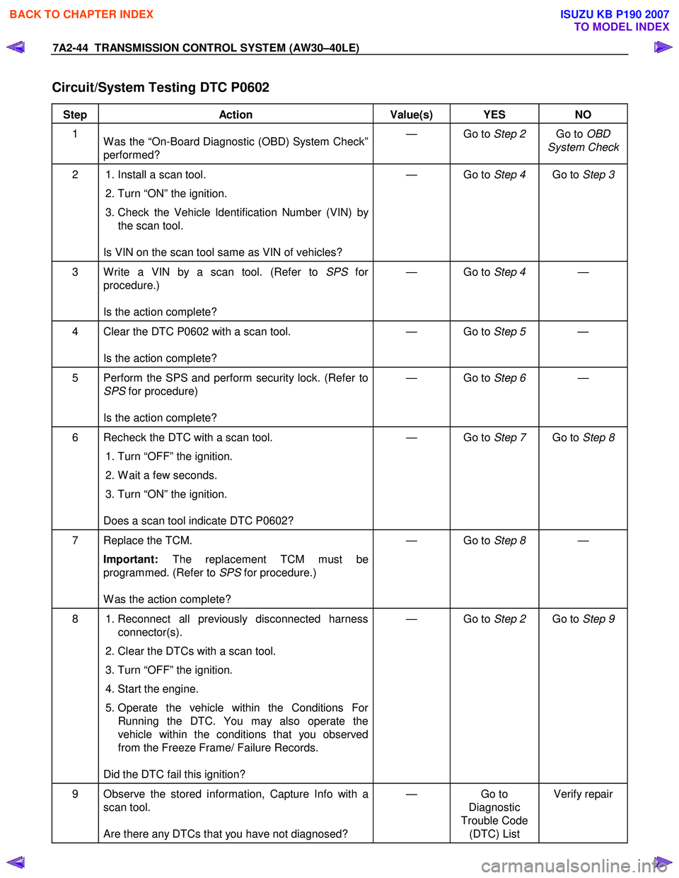
7A2-44 TRANSMISSION CONTROL SYSTEM (AW30–40LE)
Circuit/System Testing DTC P0602
Step Action Value(s) YES NO
1
W as the “On-Board Diagnostic (OBD) System Check”
performed? — Go to
Step 2 Go to OBD
System Check
2 1. Install a scan tool.
2. Turn “ON” the ignition.
3. Check the Vehicle Identification Number (VIN) by the scan tool.
Is VIN on the scan tool same as VIN of vehicles? — Go to
Step 4 Go to Step 3
3 W rite a VIN by a scan tool. (Refer to SPS for
procedure.)
Is the action complete? — Go to
Step 4 —
4 Clear the DTC P0602 with a scan tool.
Is the action complete? — Go to
Step 5 —
5 Perform the SPS and perform security lock. (Refer to
SPS for procedure)
Is the action complete? — Go to
Step 6 —
6 Recheck the DTC with a scan tool.
1. Turn “OFF” the ignition.
2. W ait a few seconds.
3. Turn “ON” the ignition.
Does a scan tool indicate DTC P0602? — Go to
Step 7 Go to Step 8
7 Replace the TCM.
Important: The replacement TCM must be
programmed. (Refer to SPS for procedure.)
W as the action complete? — Go to
Step 8 —
8 1. Reconnect all previously disconnected harness
connector(s).
2. Clear the DTCs with a scan tool.
3. Turn “OFF” the ignition.
4. Start the engine.
5. Operate the vehicle within the Conditions For Running the DTC. You may also operate the
vehicle within the conditions that you observed
from the Freeze Frame/ Failure Records.
Did the DTC fail this ignition? — Go to
Step 2 Go to Step 9
9 Observe the stored information, Capture Info with a
scan tool.
Are there any DTCs that you have not diagnosed? — Go
to
Diagnostic
Trouble Code (DTC) List Verify repair
BACK TO CHAPTER INDEX
TO MODEL INDEX
ISUZU KB P190 2007
Page 4014 of 6020
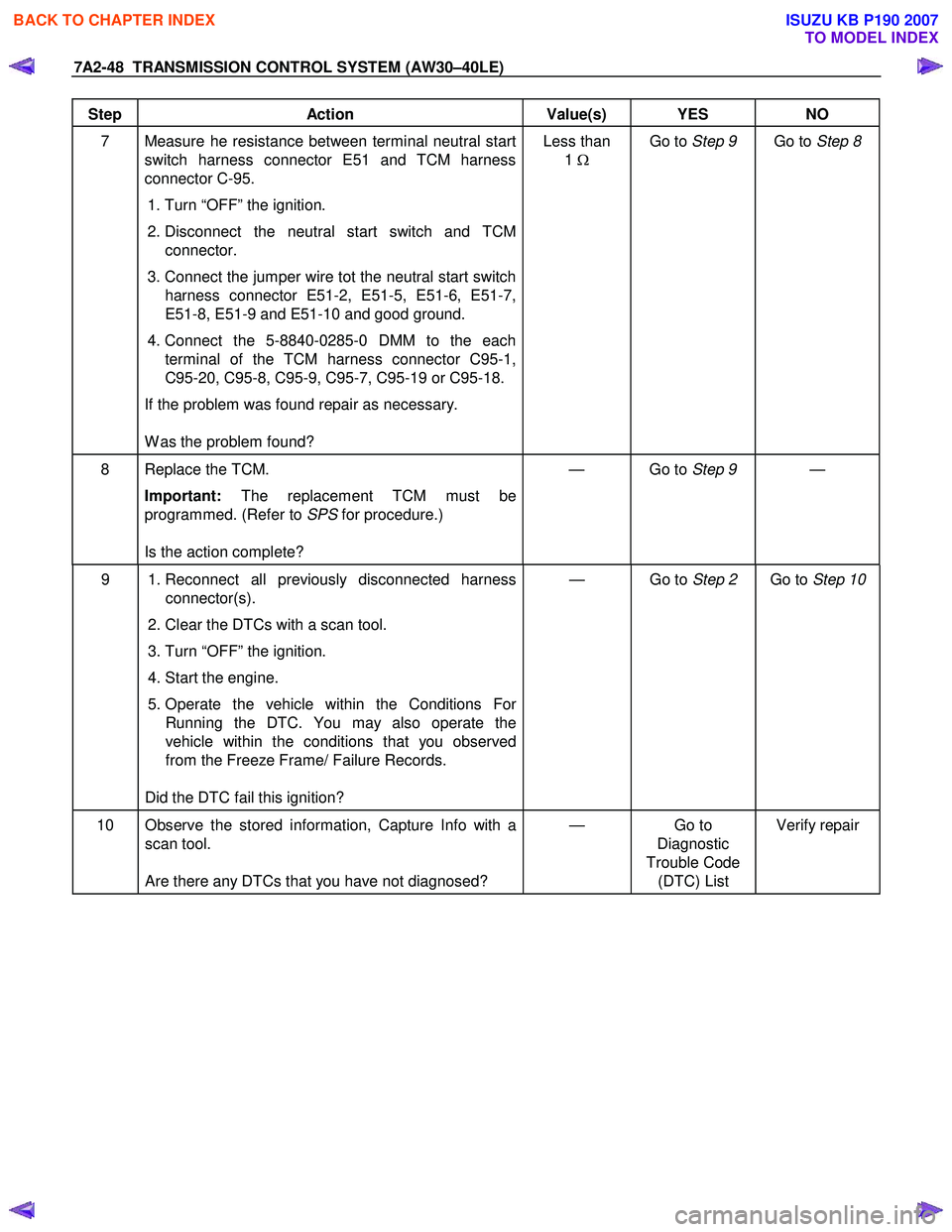
7A2-48 TRANSMISSION CONTROL SYSTEM (AW30–40LE)
Step Action Value(s) YES NO
7 Measure he resistance between terminal neutral start
switch harness connector E51 and TCM harness
connector C-95.
1. Turn “OFF” the ignition.
2. Disconnect the neutral start switch and TCM connector.
3. Connect the jumper wire tot the neutral start switch harness connector E51-2, E51-5, E51-6, E51-7,
E51-8, E51-9 and E51-10 and good ground.
4. Connect the 5-8840-0285-0 DMM to the each terminal of the TCM harness connector C95-1,
C95-20, C95-8, C95-9, C95-7, C95-19 or C95-18.
If the problem was found repair as necessary.
W as the problem found? Less than
1 Ω
Go to Step 9 Go to Step 8
8 Replace the TCM.
Important: The replacement TCM must be
programmed. (Refer to SPS for procedure.)
Is the action complete? — Go to
Step 9 —
9 1. Reconnect all previously disconnected harness
connector(s).
2. Clear the DTCs with a scan tool.
3. Turn “OFF” the ignition.
4. Start the engine.
5. Operate the vehicle within the Conditions For Running the DTC. You may also operate the
vehicle within the conditions that you observed
from the Freeze Frame/ Failure Records.
Did the DTC fail this ignition? — Go to
Step 2 Go to Step 10
10 Observe the stored information, Capture Info with a
scan tool.
Are there any DTCs that you have not diagnosed? — Go
to
Diagnostic
Trouble Code (DTC) List Verify repair
BACK TO CHAPTER INDEX
TO MODEL INDEX
ISUZU KB P190 2007
Page 4017 of 6020
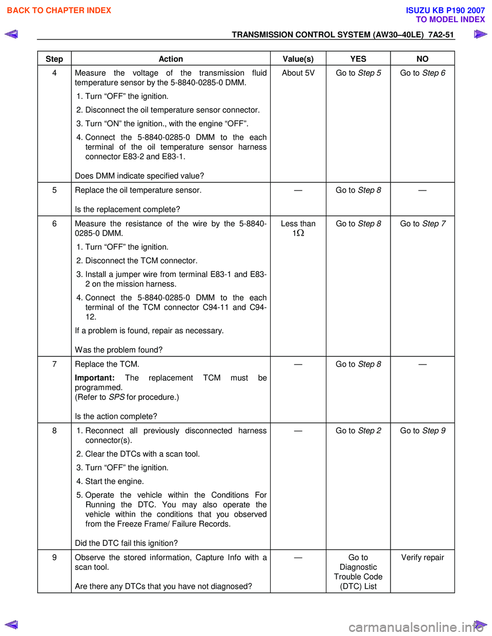
TRANSMISSION CONTROL SYSTEM (AW30–40LE) 7A2-51
Step Action Value(s) YES NO
4 Measure the voltage of the transmission fluid
temperature sensor by the 5-8840-0285-0 DMM.
1. Turn “OFF” the ignition.
2. Disconnect the oil temperature sensor connector.
3. Turn “ON” the ignition., with the engine “OFF”.
4. Connect the 5-8840-0285-0 DMM to the each
terminal of the oil temperature sensor harness
connector E83-2 and E83-1.
Does DMM indicate specified value? About 5V Go to
Step 5 Go to Step 6
5 Replace the oil temperature sensor.
Is the replacement complete? — Go to
Step 8 —
6 Measure the resistance of the wire by the 5-8840-
0285-0 DMM.
1. Turn “OFF” the ignition.
2. Disconnect the TCM connector.
3. Install a jumper wire from terminal E83-1 and E83-
2 on the mission harness.
4. Connect the 5-8840-0285-0 DMM to the each
terminal of the TCM connector C94-11 and C94-
12.
If a problem is found, repair as necessary.
W as the problem found? Less than
1
Ω
Go to Step 8 Go to Step 7
7 Replace the TCM.
Important: The replacement TCM must be
programmed.
(Refer to SPS for procedure.)
Is the action complete? — Go to
Step 8 —
8 1. Reconnect all previously disconnected harness
connector(s).
2. Clear the DTCs with a scan tool.
3. Turn “OFF” the ignition.
4. Start the engine.
5. Operate the vehicle within the Conditions For Running the DTC. You may also operate the
vehicle within the conditions that you observed
from the Freeze Frame/ Failure Records.
Did the DTC fail this ignition? — Go to
Step 2 Go to Step 9
9 Observe the stored information, Capture Info with a
scan tool.
Are there any DTCs that you have not diagnosed? — Go
to
Diagnostic
Trouble Code (DTC) List Verify repair
BACK TO CHAPTER INDEX
TO MODEL INDEX
ISUZU KB P190 2007
Page 4020 of 6020
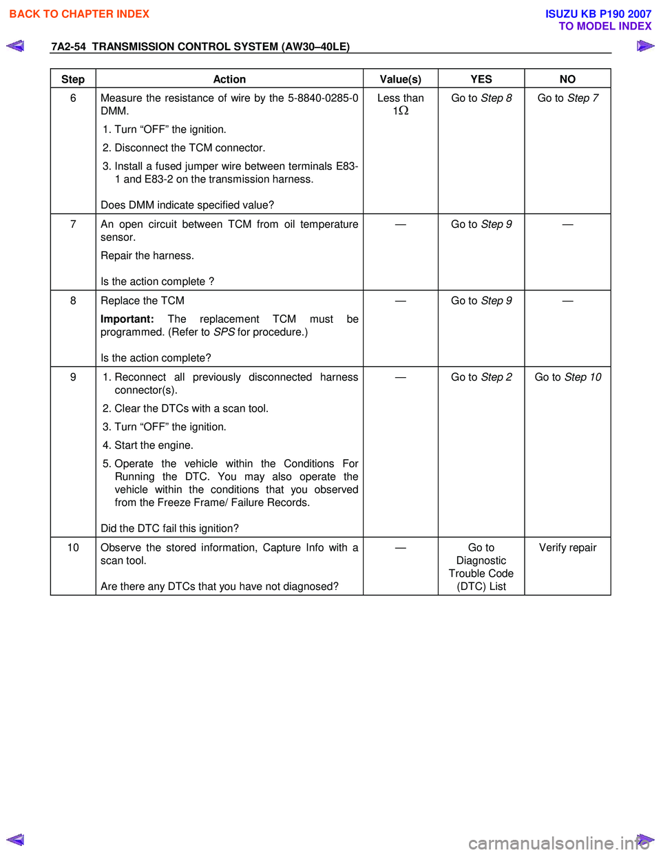
7A2-54 TRANSMISSION CONTROL SYSTEM (AW30–40LE)
Step Action Value(s) YES NO
6 Measure the resistance of wire by the 5-8840-0285-0
DMM.
1. Turn “OFF” the ignition.
2. Disconnect the TCM connector.
3. Install a fused jumper wire between terminals E83-
1 and E83-2 on the transmission harness.
Does DMM indicate specified value? Less than
1
Ω
Go to Step 8 Go to Step 7
7 An open circuit between TCM from oil temperature
sensor.
Repair the harness.
Is the action complete ? — Go to
Step 9 —
8 Replace the TCM
Important: The replacement TCM must be
programmed. (Refer to SPS for procedure.)
Is the action complete? — Go to
Step 9 —
9 1. Reconnect all previously disconnected harness
connector(s).
2. Clear the DTCs with a scan tool.
3. Turn “OFF” the ignition.
4. Start the engine.
5. Operate the vehicle within the Conditions For Running the DTC. You may also operate the
vehicle within the conditions that you observed
from the Freeze Frame/ Failure Records.
Did the DTC fail this ignition? — Go to
Step 2 Go to Step 10
10 Observe the stored information, Capture Info with a
scan tool.
Are there any DTCs that you have not diagnosed? — Go
to
Diagnostic
Trouble Code (DTC) List Verify repair
BACK TO CHAPTER INDEX
TO MODEL INDEX
ISUZU KB P190 2007