2007 ISUZU KB P190 air condition
[x] Cancel search: air conditionPage 3896 of 6020
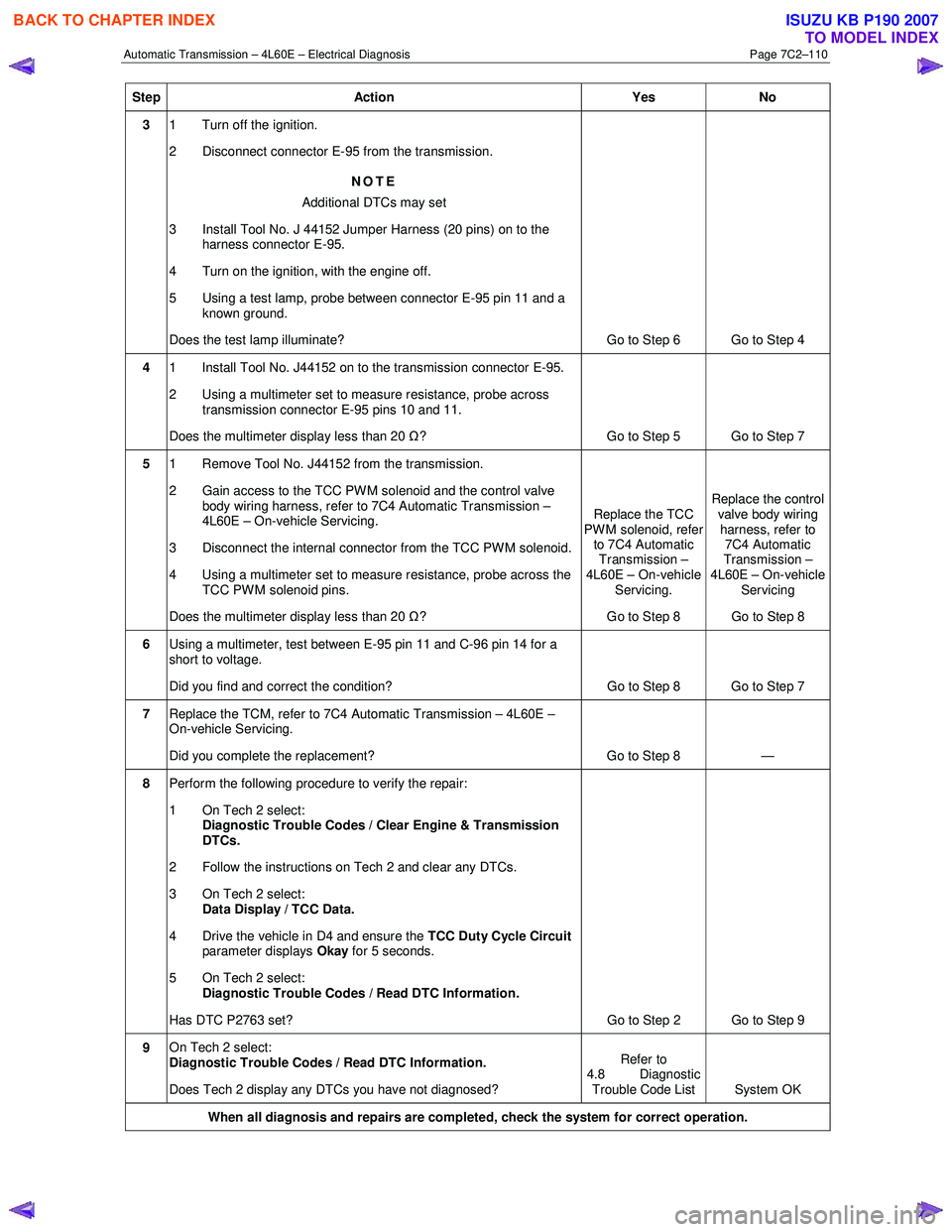
Automatic Transmission – 4L60E – Electrical Diagnosis Page 7C2–110
Step Action Yes No
3 1 Turn off the ignition.
2 Disconnect connector E-95 from the transmission.
NOTE
Additional DTCs may set
3 Install Tool No. J 44152 Jumper Harness (20 pins) on to the harness connector E-95.
4 Turn on the ignition, with the engine off.
5 Using a test lamp, probe between connector E-95 pin 11 and a known ground.
Does the test lamp illuminate? Go to Step 6 Go to Step 4
4 1 Install Tool No. J44152 on to the transmission connector E-95.
2 Using a multimeter set to measure resistance, probe across transmission connector E-95 pins 10 and 11.
Does the multimeter display less than 20 Ω? Go to Step 5 Go to Step 7
5 1 Remove Tool No. J44152 from the transmission.
2 Gain access to the TCC PWM solenoid and the control valve body wiring harness, refer to 7C4 Automatic Transmission –
4L60E – On-vehicle Servicing.
3 Disconnect the internal connector from the TCC PWM solenoid.
4 Using a multimeter set to measure resistance, probe across the TCC PWM solenoid pins.
Does the multimeter display less than 20 Ω? Replace the TCC
PWM solenoid, refer to 7C4 Automatic
Transmission –
4L60E – On-vehicle
Servicing.
Go to Step 8 Replace the control
valve body wiring harness, refer to 7C4 Automatic
Transmission –
4L60E – On-vehicle Servicing
Go to Step 8
6 Using a multimeter, test between E-95 pin 11 and C-96 pin 14 for a
short to voltage.
Did you find and correct the condition? Go to Step 8 Go to Step 7
7 Replace the TCM, refer to 7C4 Automatic Transmission – 4L60E –
On-vehicle Servicing.
Did you complete the replacement? Go to Step 8 —
8 Perform the following procedure to verify the repair:
1 On Tech 2 select: Diagnostic Trouble Codes / Clear Engine & Transmission
DTCs.
2 Follow the instructions on Tech 2 and clear any DTCs.
3 On Tech 2 select: Data Display / TCC Data.
4 Drive the vehicle in D4 and ensure the TCC Duty Cycle Circuit
parameter displays Okay for 5 seconds.
5 On Tech 2 select:
Diagnostic Trouble Codes / Read DTC Information.
Has DTC P2763 set? Go to Step 2 Go to Step 9
9 On Tech 2 select:
Diagnostic Trouble Codes / Read DTC Information.
Does Tech 2 display any DTCs you have not diagnosed? Refer to
4.8 Diagnostic
Trouble Code List System OK
When all diagnosis and repairs are completed, check the
system for correct operation.
BACK TO CHAPTER INDEX
TO MODEL INDEX
ISUZU KB P190 2007
Page 3900 of 6020
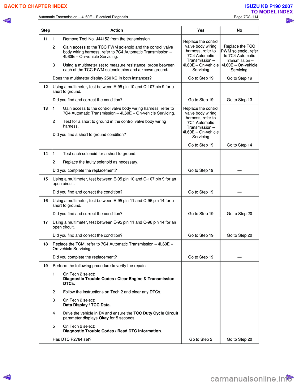
Automatic Transmission – 4L60E – Electrical Diagnosis Page 7C2–114
Step Action Yes No
11 1 Remove Tool No. J44152 from the transmission.
2 Gain access to the TCC PWM solenoid and the control valve body wiring harness, refer to 7C4 Automatic Transmission –
4L60E – On-vehicle Servicing.
3 Using a multimeter set to measure resistance, probe between each of the TCC PW M solenoid pins and a known ground.
Does the multimeter display 250 k Ω in both instances? Replace the control
valve body wiring harness, refer to
7C4 Automatic
Transmission –
4L60E – On-vehicle Servicing
Go to Step 19 Replace the TCC
PWM solenoid, refer to 7C4 Automatic Transmission –
4L60E – On-vehicle Servicing.
Go to Step 19
12 Using a multimeter, test between E-95 pin 10 and C-107 pin 9 for a
short to ground.
Did you find and correct the condition? Go to Step 19 Go to Step 13
13 1 Gain access to the control valve body wiring harness, refer to
7C4 Automatic Transmission – 4L60E – On-vehicle Servicing.
2 Test for a short to ground in the control valve body wiring harness.
Did you find a short to ground condition? Replace the control
valve body wiring harness, refer to
7C4 Automatic
Transmission –
4L60E – On-vehicle Servicing
Go to Step 19 Go to Step 14
14 1 Test each solenoid for a short to ground.
2 Replace the faulty solenoid as necessary.
Did you complete the replacement? Go to Step 19 —
15 Using a multimeter, test between E-95 pin 10 and C-107 pin 9 for an
open circuit.
Did you find and correct the condition? Go to Step 19 —
16 Using a multimeter, test between E-95 pin 11 and C-96 pin 14 for a
short to ground.
Did you find and correct the condition? Go to Step 19 Go to Step 20
17 Using a multimeter, test between E-95 pin 11 and C-96 pin 14 for an
open circuit.
Did you find and correct the condition? Go to Step 19 Go to Step 20
18 Replace the TCM, refer to 7C4 Automatic Transmission – 4L60E –
On-vehicle Servicing.
Did you complete the replacement? Go to Step 19 —
19 Perform the following procedure to verify the repair:
1 On Tech 2 select: Diagnostic Trouble Codes / Clear Engine & Transmission
DTCs.
2 Follow the instructions on Tech 2 and clear any DTCs.
3 On Tech 2 select: Data Display / TCC Data.
4 Drive the vehicle in D4 and ensure the TCC Duty Cycle Circuit
parameter displays Okay for 5 seconds.
5 On Tech 2 select:
Diagnostic Trouble Codes / Read DTC Information.
Has DTC P2764 set? Go to Step 2 Go to Step 20
BACK TO CHAPTER INDEX
TO MODEL INDEX
ISUZU KB P190 2007
Page 3901 of 6020
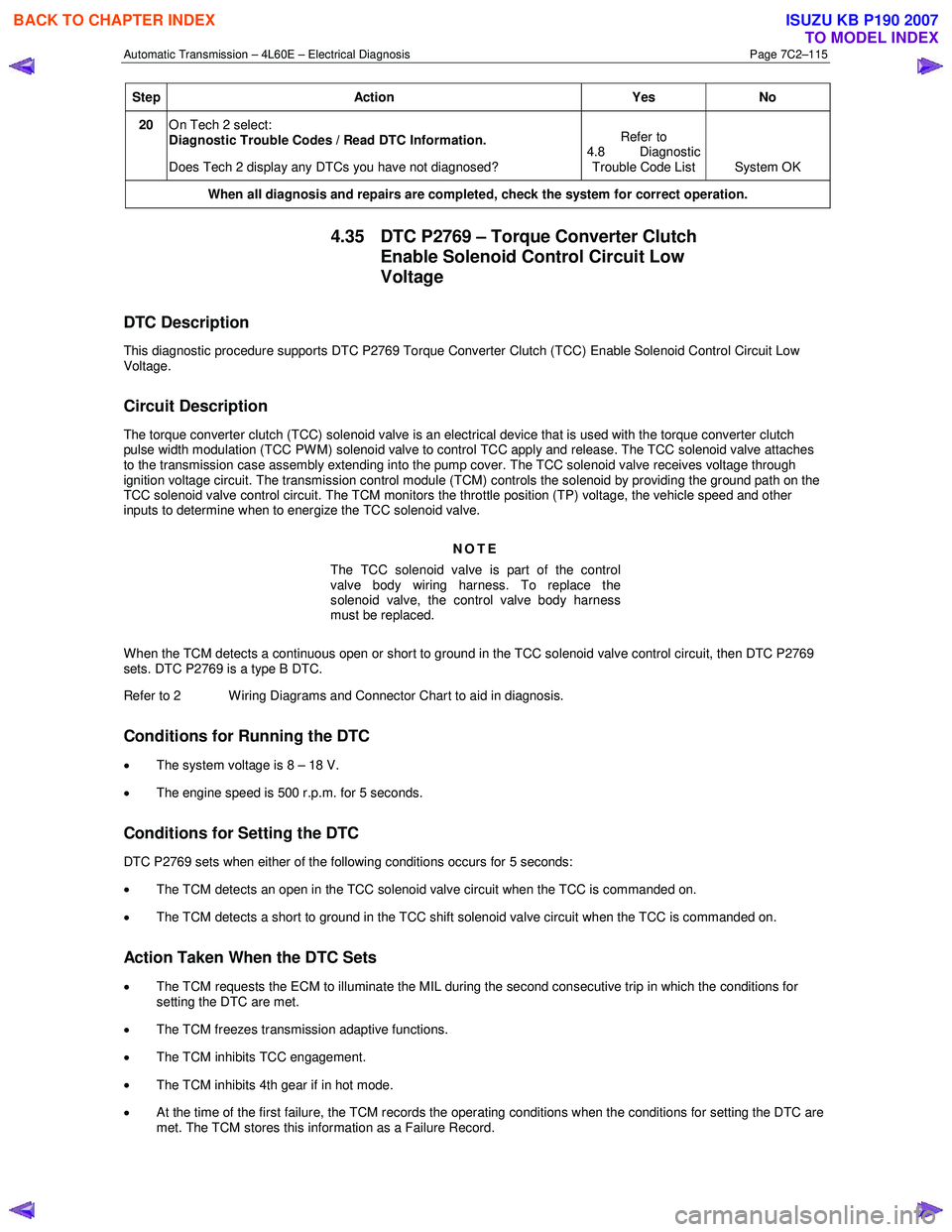
Automatic Transmission – 4L60E – Electrical Diagnosis Page 7C2–115
Step Action Yes No
20 On Tech 2 select:
Diagnostic Trouble Codes / Read DTC Information.
Does Tech 2 display any DTCs you have not diagnosed? Refer to
4.8 Diagnostic Trouble Code List System OK
When all diagnosis and repairs are completed, check the system for correct operation.
4.35 DTC P2769 – Torque Converter Clutch
Enable Solenoid Control Circuit Low
Voltage
DTC Description
This diagnostic procedure supports DTC P2769 Torque Converter Clutch (TCC) Enable Solenoid Control Circuit Low
Voltage.
Circuit Description
The torque converter clutch (TCC) solenoid valve is an electrical device that is used with the torque converter clutch
pulse width modulation (TCC PWM) solenoid valve to control TCC apply and release. The TCC solenoid valve attaches
to the transmission case assembly extending into the pump cover. The TCC solenoid valve receives voltage through
ignition voltage circuit. The transmission control module (TCM) controls the solenoid by providing the ground path on the
TCC solenoid valve control circuit. The TCM monitors the throttle position (TP) voltage, the vehicle speed and other
inputs to determine when to energize the TCC solenoid valve.
NOTE
The TCC solenoid valve is part of the control
valve body wiring harness. To replace the
solenoid valve, the control valve body harness
must be replaced.
When the TCM detects a continuous open or short to ground in the TCC solenoid valve control circuit, then DTC P2769
sets. DTC P2769 is a type B DTC.
Refer to 2 W iring Diagrams and Connector Chart to aid in diagnosis.
Conditions for Running the DTC
• The system voltage is 8 – 18 V.
• The engine speed is 500 r.p.m. for 5 seconds.
Conditions for Setting the DTC
DTC P2769 sets when either of the following conditions occurs for 5 seconds:
• The TCM detects an open in the TCC solenoid valve circuit when the TCC is commanded on.
• The TCM detects a short to ground in the TCC shift solenoid valve circuit when the TCC is commanded on.
Action Taken When the DTC Sets
• The TCM requests the ECM to illuminate the MIL during the second consecutive trip in which the conditions for
setting the DTC are met.
• The TCM freezes transmission adaptive functions.
• The TCM inhibits TCC engagement.
• The TCM inhibits 4th gear if in hot mode.
• At the time of the first failure, the TCM records the operating conditions when the conditions for setting the DTC are
met. The TCM stores this information as a Failure Record.
BACK TO CHAPTER INDEX
TO MODEL INDEX
ISUZU KB P190 2007
Page 3905 of 6020
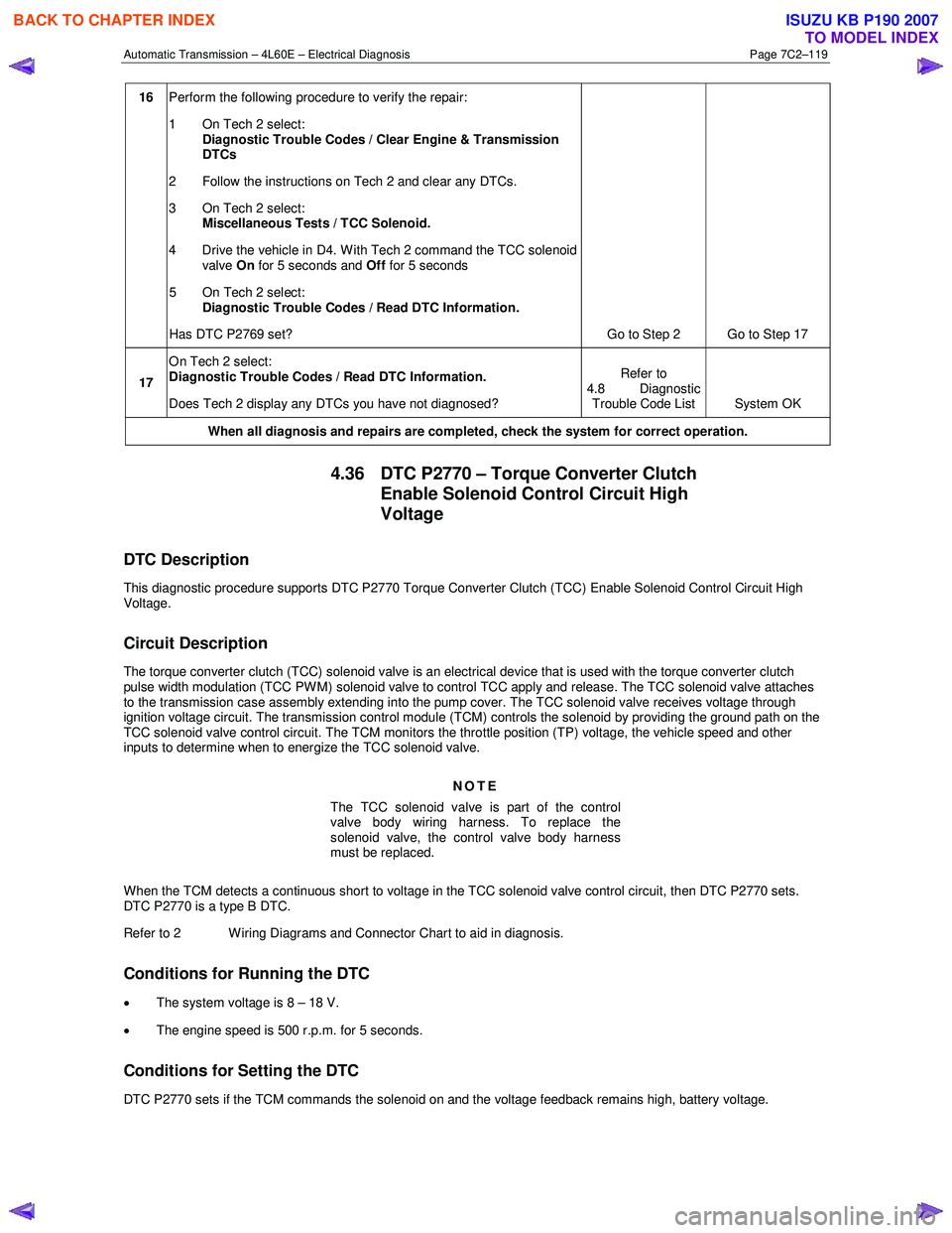
Automatic Transmission – 4L60E – Electrical Diagnosis Page 7C2–119
16 Perform the following procedure to verify the repair:
1 On Tech 2 select: Diagnostic Trouble Codes / Clear Engine & Transmission
DTCs
2 Follow the instructions on Tech 2 and clear any DTCs.
3 On Tech 2 select: Miscellaneous Tests / TCC Solenoid.
4 Drive the vehicle in D4. With Tech 2 command the TCC solenoid valve On for 5 seconds and Off for 5 seconds
5 On Tech 2 select:
Diagnostic Trouble Codes / Read DTC Information.
Has DTC P2769 set? Go to Step 2 Go to Step 17
17 On Tech 2 select:
Diagnostic Trouble Codes / Read DTC Information.
Does Tech 2 display any DTCs you have not diagnosed? Refer to
4.8 Diagnostic Trouble Code List System OK
When all diagnosis and repairs are completed, check the
system for correct operation.
4.36 DTC P2770 – Torque Converter Clutch
Enable Solenoid Control Circuit High
Voltage
DTC Description
This diagnostic procedure supports DTC P2770 Torque Converter Clutch (TCC) Enable Solenoid Control Circuit High
Voltage.
Circuit Description
The torque converter clutch (TCC) solenoid valve is an electrical device that is used with the torque converter clutch
pulse width modulation (TCC PWM) solenoid valve to control TCC apply and release. The TCC solenoid valve attaches
to the transmission case assembly extending into the pump cover. The TCC solenoid valve receives voltage through
ignition voltage circuit. The transmission control module (TCM) controls the solenoid by providing the ground path on the
TCC solenoid valve control circuit. The TCM monitors the throttle position (TP) voltage, the vehicle speed and other
inputs to determine when to energize the TCC solenoid valve.
NOTE
The TCC solenoid valve is part of the control
valve body wiring harness. To replace the
solenoid valve, the control valve body harness
must be replaced.
W hen the TCM detects a continuous short to voltage in the TCC solenoid valve control circuit, then DTC P2770 sets.
DTC P2770 is a type B DTC.
Refer to 2 W iring Diagrams and Connector Chart to aid in diagnosis.
Conditions for Running the DTC
• The system voltage is 8 – 18 V.
• The engine speed is 500 r.p.m. for 5 seconds.
Conditions for Setting the DTC
DTC P2770 sets if the TCM commands the solenoid on and the voltage feedback remains high, battery voltage.
BACK TO CHAPTER INDEX
TO MODEL INDEX
ISUZU KB P190 2007
Page 3907 of 6020
Automatic Transmission – 4L60E – Electrical Diagnosis Page 7C2–121
Step Action Yes No
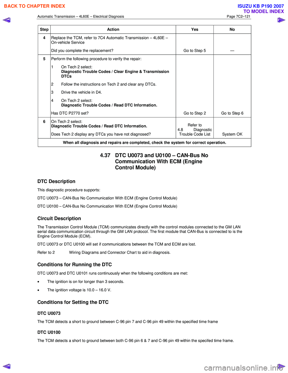
4 Replace the TCM, refer to 7C4 Automatic Transmission – 4L60E –
On-vehicle Service
Did you complete the replacement? Go to Step 5 —
5 Perform the following procedure to verify the repair:
1 On Tech 2 select: Diagnostic Trouble Codes / Clear Engine & Transmission
DTCs
2 Follow the instructions on Tech 2 and clear any DTCs.
3 Drive the vehicle in D4.
4 On Tech 2 select:
Diagnostic Trouble Codes / Read DTC Information.
Has DTC P2770 set? Go to Step 2 Go to Step 6
6 On Tech 2 select:
Diagnostic Trouble Codes / Read DTC Information.
Does Tech 2 display any DTCs you have not diagnosed? Refer to
4.8 Diagnostic Trouble Code List System OK
When all diagnosis and repairs are completed, check the
system for correct operation.
4.37 DTC U0073 and U0100 – CAN-Bus No
Communication With ECM (Engine
Control Module)
DTC Description
This diagnostic procedure supports:
DTC U0073 – CAN-Bus No Communication W ith ECM (Engine Control Module)
DTC U0100 – CAN-Bus No Communication W ith ECM (Engine Control Module)
Circuit Description
The Transmission Control Module (TCM) communicates directly with the control modules connected to the GM LAN
serial data communication circuit through the GM LAN protocol. The first module that CAN-Bus is connected to is the
Engine Control Module (ECM).
DTC U0073 or DTC U0100 will set if communications between the TCM and ECM are lost.
Refer to 2 W iring Diagrams and Connector Chart to aid in diagnosis.
Conditions for Running the DTC
DTC U0073 and DTC U0101 runs continuously when the following conditions are met:
• The ignition is on for longer than 3 seconds.
• The ignition voltage is 10.0 – 16.0 V.
Conditions for Setting the DTC
DTC U0073
The TCM detects a short to ground between C-96 pin 7 and C-96 pin 49 within the specified time frame
DTC U0100
The TCM detects a short to ground between both C-96 pin 6 & 7 and C-96 pin 49 within the specifed time frame.
BACK TO CHAPTER INDEX
TO MODEL INDEX
ISUZU KB P190 2007
Page 3909 of 6020
Automatic Transmission – 4L60E – Electrical Diagnosis Page 7C2–123
Step Action Yes No
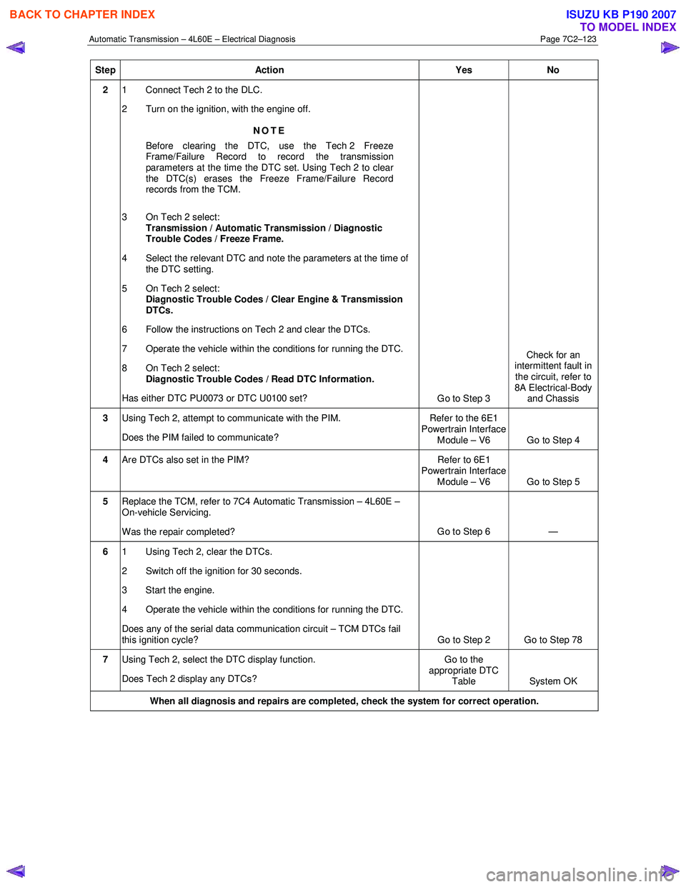
2 1 Connect Tech 2 to the DLC.
2 Turn on the ignition, with the engine off.
NOTE
Before clearing the DTC, use the Tech 2 Freeze
Frame/Failure Record to record the transmission
parameters at the time the DTC set. Using Tech 2 to clear
the DTC(s) erases the Freeze Frame/Failure Record
records from the TCM.
3 On Tech 2 select: Transmission / Automatic Transmission / Diagnostic
Trouble Codes / Freeze Frame.
4 Select the relevant DTC and note the parameters at the time of the DTC setting.
5 On Tech 2 select:
Diagnostic Trouble Codes / Clear Engine & Transmission
DTCs.
6 Follow the instructions on Tech 2 and clear the DTCs.
7 Operate the vehicle within the conditions for running the DTC.
8 On Tech 2 select:
Diagnostic Trouble Codes / Read DTC Information.
Has either DTC PU0073 or DTC U0100 set? Go to Step 3 Check for an
intermittent fault in the circuit, refer to
8A Electrical-Body and Chassis
3 Using Tech 2, attempt to communicate with the PIM.
Does the PIM failed to communicate? Refer to the 6E1
Powertrain Interface Module – V6 Go to Step 4
4 Are DTCs also set in the PIM? Refer to 6E1
Powertrain Interface
Module – V6 Go to Step 5
5 Replace the TCM, refer to 7C4 Automatic Transmission – 4L60E –
On-vehicle Servicing.
Was the repair completed? Go to Step 6
—
6 1 Using Tech 2, clear the DTCs.
2 Switch off the ignition for 30 seconds.
3 Start the engine.
4 Operate the vehicle within the conditions for running the DTC.
Does any of the serial data communication circuit – TCM DTCs fail
this ignition cycle? Go to Step 2 Go to Step 78
7 Using Tech 2, select the DTC display function.
Does Tech 2 display any DTCs? Go to the
appropriate DTC Table System OK
When all diagnosis and repairs are completed, check the system for correct operation.
BACK TO CHAPTER INDEX
TO MODEL INDEX
ISUZU KB P190 2007
Page 3917 of 6020
Automatic Transmission – 4L60E – On-vehicle Servicing Page 7C4–4
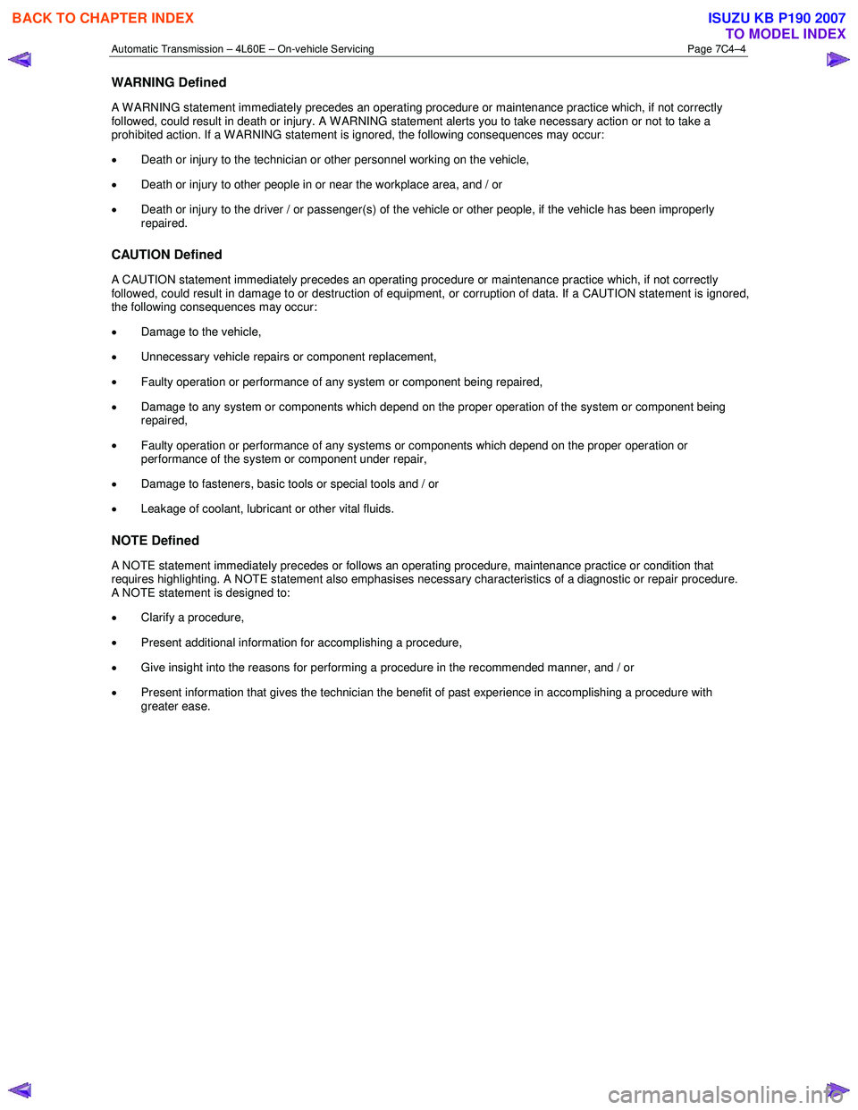
WARNING Defined
A W ARNING statement immediately precedes an operating procedure or maintenance practice which, if not correctly
followed, could result in death or injury. A WARNING statement alerts you to take necessary action or not to take a
prohibited action. If a W ARNING statement is ignored, the following consequences may occur:
• Death or injury to the technician or other personnel working on the vehicle,
• Death or injury to other people in or near the workplace area, and / or
• Death or injury to the driver / or passenger(s) of the vehicle or other people, if the vehicle has been improperly
repaired.
CAUTION Defined
A CAUTION statement immediately precedes an operating procedure or maintenance practice which, if not correctly
followed, could result in damage to or destruction of equipment, or corruption of data. If a CAUTION statement is ignored,
the following consequences may occur:
• Damage to the vehicle,
• Unnecessary vehicle repairs or component replacement,
• Faulty operation or performance of any system or component being repaired,
• Damage to any system or components which depend on the proper operation of the system or component being
repaired,
• Faulty operation or performance of any systems or components which depend on the proper operation or
performance of the system or component under repair,
• Damage to fasteners, basic tools or special tools and / or
• Leakage of coolant, lubricant or other vital fluids.
NOTE Defined
A NOTE statement immediately precedes or follows an operating procedure, maintenance practice or condition that
requires highlighting. A NOTE statement also emphasises necessary characteristics of a diagnostic or repair procedure.
A NOTE statement is designed to:
• Clarify a procedure,
• Present additional information for accomplishing a procedure,
• Give insight into the reasons for performing a procedure in the recommended manner, and / or
• Present information that gives the technician the benefit of past experience in accomplishing a procedure with
greater ease.
BACK TO CHAPTER INDEX
TO MODEL INDEX
ISUZU KB P190 2007
Page 3919 of 6020

Automatic Transmission – 4L60E – On-vehicle Servicing Page 7C4–6
6 Lift the locking lever (1) on the transmission fluid
indicator, then remove the indicator from the filler
tube (2) and check the fluid colour, condition and level.
Do not overfill the transmission. Overfilling
can cause aeration resulting in fluid loss,
shift complaints and possible damage to the
transmission.
7 If the transmission fluid level is low, add only enough of the recommended fluid until
its level shows onto the
crosshatch hot area (3) of the fluid indicator.
Figure 7C4 – 1
2.2 Reverse Flush and Flow Rate Test
It is essential to perform a reverse flush and oil cooler flow rate test after any of the following:
• the transmission is repaired or replaced,
• fluid contamination is suspected, or
• whenever the oil pump and/or torque converter is replaced.
NOTE
The reverse flush must be completed prior to
conducting a flow rate test.
Reverse Flush
1 Disconnect both cooler hose/line assemblies at the transmission and at the radiator cooler, refer to 3.17 Transmission Cooler Line/Hose Assemblies.
2 Check the cooler hose/line to radiator cooler fittings for damage, replace as required.
To avoid personal injury, wear safety glasses
when using compressed air.
3 Carefully check the radiator cooler lower fitting to see if any foreign material is evident at this point. If foreign material is found, remove it with a suitable tool and/or compressed air at a reduced pressure of approximately
345 kPa blown in the reverse direction through the cooler.
4 Using compressed air at a reduced pressure of approximately 345 kPa blown in a reverse direction, clean the cooler hose/line assemblies.
5 Reconnect the cooler outlet line to the transmission and both cooler hose/line assemblies to the radiator cooler fittings, refer to 3.17 Transmission Cooler Line/Hose Assemblies.
NOTE
Do not reconnect the cooler inlet line at the
transmission end. This line needs to be left
disconnected to perform the flow rate test.
6 Perform the flow rate test, refer to Flow Rate Test in this Section.
BACK TO CHAPTER INDEX
TO MODEL INDEX
ISUZU KB P190 2007