Page 4794 of 6020
7C-16 CLUTCH
TORQUE SPECIFICATION
STANDARD BOLTS
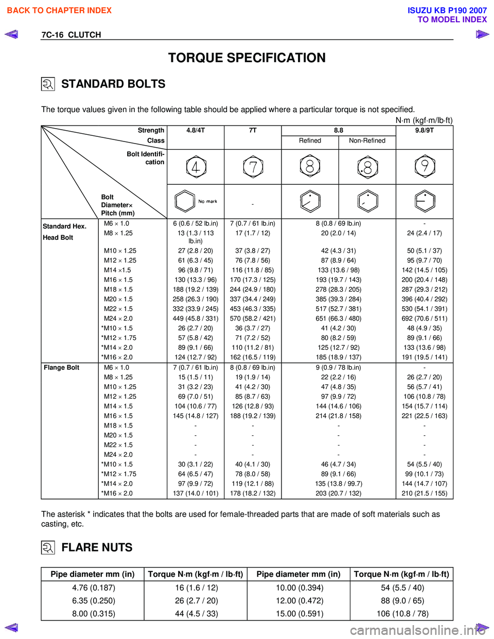
The torque values given in the following table should be applied where a particular torque is not specified.
N⋅m (kgf ⋅m/lb ⋅ft)
Strength 4.8/4T 7T 8.8 9.8/9T
Class Refined Non-Refined
Bolt Identifi-
cation
Bolt
Diameter ×
××
×
Pitch (mm)
-
M6 × 1.0 6 (0.6 / 52 lb.in) 7 (0.7 / 61 lb.in) 8 (0.8 / 69 lb.in) -
M8 × 1.25 13 (1.3 / 113
lb.in) 17 (1.7 / 12)
20 (2.0 / 14) 24 (2.4 / 17)
M10 × 1.25 27 (2.8 / 20) 37 (3.8 / 27) 42 (4.3 / 31) 50 (5.1 / 37)
M12 × 1.25 61 (6.3 / 45) 76 (7.8 / 56) 87 (8.9 / 64) 95 (9.7 / 70)
M14 ×1.5 96 (9.8 / 71) 116 (11.8 / 85) 133 (13.6 / 98) 142 (14.5 / 105)
M16 × 1.5 130 (13.3 / 96) 170 (17.3 / 125) 193 (19.7 / 143) 200 (20.4 / 148)
M18 × 1.5 188 (19.2 / 139) 244 (24.9 / 180) 278 (28.3 / 205) 287 (29.3 / 212)
M20 × 1.5 258 (26.3 / 190) 337 (34.4 / 249) 385 (39.3 / 284) 396 (40.4 / 292)
M22 × 1.5 332 (33.9 / 245) 453 (46.3 / 335) 517 (52.7 / 381) 530 (54.1 / 391)
M24 × 2.0 449 (45.8 / 331) 570 (58.2 / 421) 651 (66.3 / 480) 692 (70.6 / 511)
* M10 × 1.5 26 (2.7 / 20) 36 (3.7 / 27) 41 (4.2 / 30) 48 (4.9 / 35)
* M12 × 1.75 57 (5.8 / 42) 71 (7.2 / 52) 80 (8.2 / 59) 89 (9.1 / 66)
* M14 × 2.0 89 (9.1 / 66) 110 (11.2 / 81) 125 (12.7 / 92) 133 (13.6 / 98)
* M16 × 2.0 124 (12.7 / 92) 162 (16.5 / 119) 185 (18.9 / 137) 191 (19.5 / 141)
Flange Bolt M6 × 1.0 7 (0.7 / 61 lb.in) 8 (0.8 / 69 lb.in) 9 (0.9 / 78 lb.in) -
M8 × 1.25 15 (1.5 / 11) 19 (1.9 / 14) 22 (2.2 / 16) 26 (2.7 / 20)
M10 × 1.25 31 (3.2 / 23) 41 (4.2 / 30) 47 (4.8 / 35) 56 (5.7 / 41)
M12 × 1.25 69 (7.0 / 51) 85 (8.7 / 63) 97 (9.9 / 72) 106 (10.8 / 78)
M14 × 1.5 104 (10.6 / 77) 126 (12.8 / 93) 144 (14.6 / 106) 154 (15.7 / 114)
M16 × 1.5 145 (14.8 / 127) 188 (19.2 / 139) 214 (21.8 / 158) 221 (22.5 / 163)
M18 × 1.5 - - - -
M20 × 1.5 - - - -
M22 × 1.5 - - - -
M24 × 2.0 - - - -
* M10 × 1.5 30 (3.1 / 22) 40 (4.1 / 30) 46 (4.7 / 34) 54 (5.5 / 40)
* M12 × 1.75 64 (6.5 / 47) 78 (8.0 / 58) 89 (9.1 / 66) 99 (10.1 / 73)
* M14 × 2.0 97 (9.9 / 72) 119 (12.1 / 88) 135 (13.8 / 99.7) 144 (14.7 / 107)
* M16 × 2.0 137 (14.0 / 101) 178 (18.2 / 132) 203 (20.7 / 132) 210 (21.5 / 155)
The asterisk * indicates that the bolts are used for female-threaded parts that are made of soft materials such as
casting, etc.
FLARE NUTS
Pipe diameter mm (in) Torque N ⋅
⋅⋅
⋅
m (kgf ⋅
⋅⋅
⋅
m / lb ⋅
⋅⋅
⋅
ft) Pipe diameter mm (in) Torque N ⋅
⋅⋅
⋅
m (kgf ⋅
⋅⋅
⋅
m / lb ⋅
⋅⋅
⋅
ft)
4.76 (0.187) 16 (1.6 / 12) 10.00 (0.394) 54 (5.5 / 40)
6.35 (0.250) 26 (2.7 / 20) 12.00 (0.472) 88 (9.0 / 65)
8.00 (0.315) 44 (4.5 / 33) 15.00 (0.591) 106 (10.8 / 78)
Standard Hex.
Head Bolt
BACK TO CHAPTER INDEX
TO MODEL INDEX
ISUZU KB P190 2007
Page 4795 of 6020
CLUTCH 7C-17
TORQUE SPECIFICATIONS
N⋅m (kgf ⋅m/lb ⋅ft)
BACK TO CHAPTER INDEX
TO MODEL INDEX
ISUZU KB P190 2007
Page 4802 of 6020
7C-24 CLUTCH
015RW 053
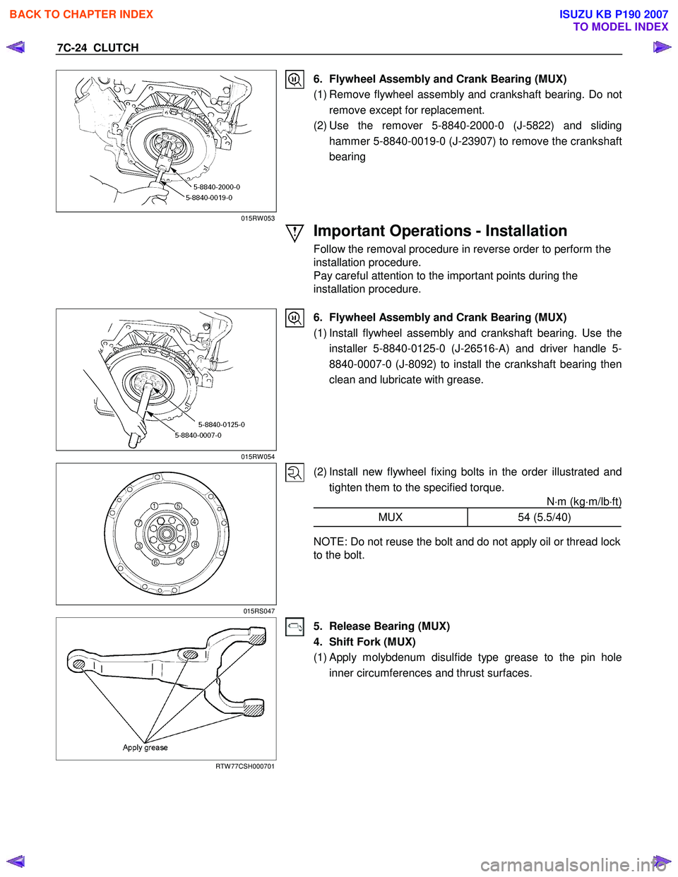
6. Flywheel Assembly and Crank Bearing (MUX)
(1) Remove flywheel assembly and crankshaft bearing. Do not remove except for replacement.
(2) Use the remover 5-8840-2000-0 (J-5822) and sliding hammer 5-8840-0019-0 (J-23907) to remove the crankshaft
bearing
Important Operations - Installation
Follow the removal procedure in reverse order to perform the
installation procedure.
Pay careful attention to the important points during the
installation procedure.
015RW 054
6. Flywheel Assembly and Crank Bearing (MUX)
(1) Install flywheel assembly and crankshaft bearing. Use the installer 5-8840-0125-0 (J-26516-A) and driver handle 5-
8840-0007-0 (J-8092) to install the crankshaft bearing then
clean and lubricate with grease.
015RS047
(2) Install new flywheel fixing bolts in the order illustrated and tighten them to the specified torque. N⋅m (kg ⋅m/lb ⋅ft)
MUX 54 (5.5/40)
NOTE: Do not reuse the bolt and do not apply oil or thread lock
to the bolt.
RTW 77CSH000701
5. Release Bearing (MUX)
4. Shift Fork (MUX)
(1)
Apply molybdenum disulfide type grease to the pin hole
inner circumferences and thrust surfaces.
BACK TO CHAPTER INDEX
TO MODEL INDEX
ISUZU KB P190 2007
Page 4803 of 6020
CLUTCH 7C-25
201RW 012
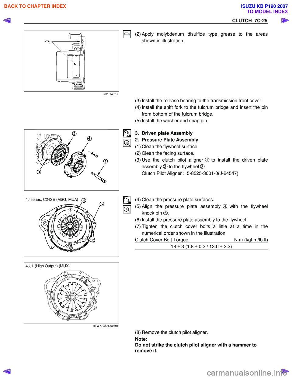
(2) Apply molybdenum disulfide type grease to the areas shown in illustration.
(3) Install the release bearing to the transmission front cover.
(4) Install the shift fork to the fulcrum bridge and insert the pin from bottom of the fulcrum bridge.
(5) Install the washer and snap pin.
3. Driven plate Assembly
2. Pressure Plate Assembly
(1) Clean the flywheel surface.
(2) Clean the facing surface.
(3) Use the clutch pilot aligner
1 to install the driven plate
assembly
2 to the flywheel 3.
Clutch Pilot Aligner : 5-8525-3001-0(J-24547)
4 4J series, C24SE (MSG, MUA)
(4) Clean the pressure plate surfaces.
(5) Align the pressure plate assembly
4 with the flywheel
knock pin
5.
(6) Install the pressure plate assembly to the flywheel.
(7) Tighten the clutch cover bolts a little at a time in the numerical order shown in the illustration.
Clutch Cover Bolt Torque N⋅m (kgf ⋅m/lb ⋅ft)
18 ± 3 (1.8 ± 0.3 / 13.0 ± 2.2)
4JJ1 (High Output) (MUX)
RTW 77CSH000601
(8) Remove the clutch pilot aligner.
Note:
Do not strike the clutch pilot aligner with a hammer to
remove it.
BACK TO CHAPTER INDEX
TO MODEL INDEX
ISUZU KB P190 2007
Page 4832 of 6020
7D-2 TRANSFER CASE
Service Precaution
WARNING: THIS VEHICLE HAS A SUPPLEMENTAL
RESTRAINT SYSTEM (SRS). REFER TO THE SRS
COMPONENT AND WIRING LOCATION VIEW IN
ORDER TO DETERMINE WHETHER YOU ARE
PERFORMING SERVICE ON OR NEAR THE SRS
COMPONENTS OR THE SRS WIRING. WHEN YOU
ARE PERFORMING SERVICE ON OR NEAR THE SRS
COMPONENTS OR THE SRS WIRING, REFER TO
THE SRS SERVICE INFORMATION. FAILURE TO
FOLLOW WARNINGS COULD RESULT IN POSSIBLE
AIR BAG DEPLOYMENT, PERSONAL INJURY, OR
OTHERWISE UNNECESSARY SRS SYSTEM
REPAIRS.
CAUTION: Always use the correct fastener in the
proper location. When you replace a fastener, use
ONLY the exact part number for that application.
ISUZU/GM will call out those fasteners that require a
replacement after removal. ISUZU/GM will also call
out the fasteners that require thread lockers or
thread sealant. UNLESS OTHERWISE SPECIFIED,
do not use supplemental coatings (Paints, greases,
or other corrosion inhibitors) on threaded fasteners
or fastener joint interfaces. Generally, such coatings
adversely affect the fastener torque and the joint
clamping force, and may damage the fastener. When
you install fasteners, use the correct tightening
sequence and specifications. Following these
instructions can help you avoid damage to parts and
systems.
BACK TO CHAPTER INDEX
TO MODEL INDEX
ISUZU KB P190 2007
Page 4834 of 6020
7D-4 TRANSFER CASE
On-Vehicle Service
Transfer Case Oil Level
RTW 67DMF000101
Legend
(1) Transfer Case
(2) Filler Plug and O-ring
Removal
1. Disconnect the battery ground cable.
2. Rise and support the vehicle with suitable stands.
3. Remove the filler plug and O-ring.
4. Check the oil level reaches the filler hole.
5. If the oil level is low, fill the transfer oil (5W -30) o
r
equivalent to the transfer through the filler hole.
Installation
1. Replace the filler plug and O-ring tighten it to the
specified torque.
Filler plug torque: 39 N ⋅
⋅⋅
⋅
m (4.0 kgf ⋅
⋅⋅
⋅
m/29 lb ⋅
⋅⋅
⋅
ft)
2. Lower the vehicle to the ground.
3. Connect the battery ground cable.
BACK TO CHAPTER INDEX
TO MODEL INDEX
ISUZU KB P190 2007
Page 4835 of 6020
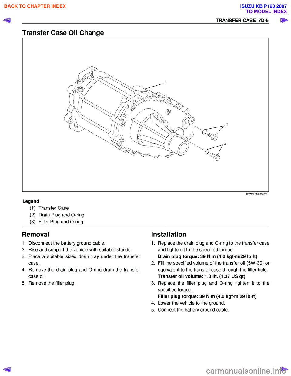
TRANSFER CASE 7D-5
Transfer Case Oil Change
RTW 67DMF000201
Legend
(1) Transfer Case
(2) Drain Plug and O-ring
(3) Filler Plug and O-ring
Removal
1. Disconnect the battery ground cable.
2. Rise and support the vehicle with suitable stands.
3. Place a suitable sized drain tray under the transfe
r
case.
4. Remove the drain plug and O-ring drain the transfe
r
case oil.
5. Remove the filler plug.
Installation
1. Replace the drain plug and O-ring to the transfer case
and tighten it to the specified torque.
Drain plug torque: 39 N ⋅
⋅⋅
⋅
m (4.0 kgf ⋅
⋅⋅
⋅
m/29 lb ⋅
⋅⋅
⋅
ft)
2. Fill the specified volume of the transfer oil (5W -30) o
r
equivalent to the transfer case through the filler hole.
Transfer oil volume: 1.3 lit. (1.37 US qt)
3. Replace the filler plug and O-ring tighten it to the specified torque.
Filler plug torque: 39 N ⋅
⋅⋅
⋅
m (4.0 kgf ⋅
⋅⋅
⋅
m/29 lb ⋅
⋅⋅
⋅
ft)
4. Lower the vehicle to the ground.
5. Connect the battery ground cable.
BACK TO CHAPTER INDEX
TO MODEL INDEX
ISUZU KB P190 2007
Page 4837 of 6020
TRANSFER CASE 7D-7
Installation
1. Thoroughly clean around the oil seal bore in the case
and ensure there are no burrs.
2.
Apply the engine oil to the new oil seal outer surfaces
and apply the recommended grease (BESCO L2) o
r
equivalent to the oil seal lip.
3. Tap the oil seal in to place, use an oil seal installe
r
(5-8840-2785-0) and a soft hammer.
RTW 77DSH000301
4. Install the output flange to the front output shaft.
5. Apply the engine oil to the new O-ring and install it to the front output shaft.
6. Secure the output flange with a flange holde
r
(5-8840-0133-0).
7. Install the new end nut and tighten them to specified torque.
Front coupling driver fixing nut torque: 137 N ⋅
⋅⋅
⋅
m (14.0 kgf ⋅
⋅⋅
⋅
m/101 lb ⋅
⋅⋅
⋅
ft)
8. Use a punch (5-8840-2293-0) to caulk the end nut.
226R300012
RUW 34DSH000301
Legend
(1) MAX 26mm (1.02in)
(2) MIN 4mm (0.16in)
BACK TO CHAPTER INDEX
TO MODEL INDEX
ISUZU KB P190 2007