2007 ISUZU KB P190 torque
[x] Cancel search: torquePage 4871 of 6020
TRANSFER CASE 7D-41
Main Data and Specifications
General Specifications
Type Synchronized type gears shifting between the 2 and 4 wheel drive mode.
Planetary type gears shifting between “low" and “high".
Control method Remote control with the button switch on the instrument panel for gears
shifting among “2H", “4H" and “4L".
Gear ratio High; 1.000
Low; 2.482
Oil capacity 1.3 lit. (1.37 US qt)
Type of lubricant BESCO GEAR OIL TRANSAXLE (5W -30)
Refer to Section 0B
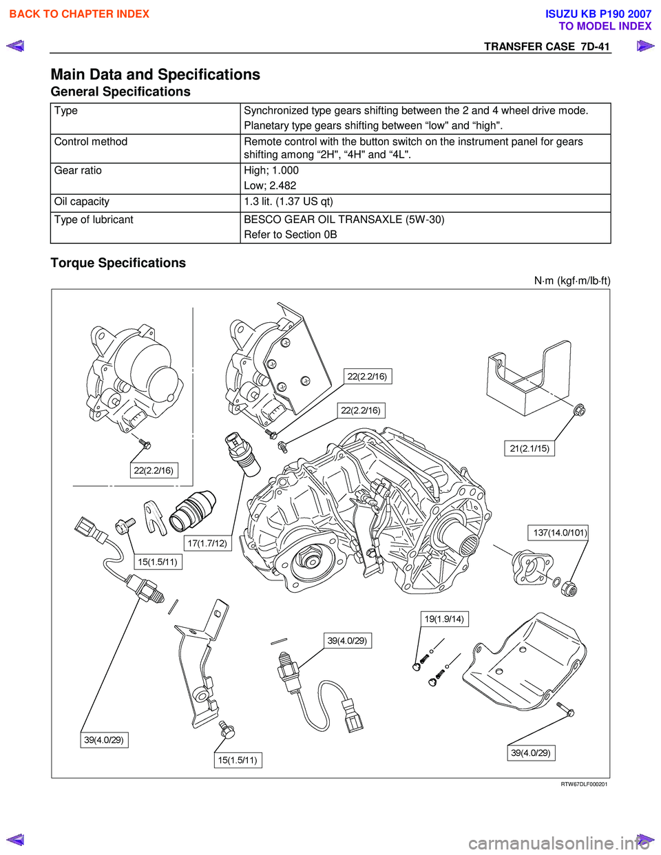
Torque Specifications
N⋅m (kgf ⋅m/lb ⋅ft)
RTW 67DLF000201
BACK TO CHAPTER INDEX
TO MODEL INDEX
ISUZU KB P190 2007
Page 4876 of 6020
7D1-2 TRANSFER CONTROL SYSTEM
Service Precaution
WARNING:
THIS VEHICLE HAS A SUPPLEMENTAL RESTRAINT
SYSTEM (SRS). REFER TO THE SRS COMPONENT AND
WIRING LOCATION VIEW IN ORDER TO DETERMINE
WHETHER YOU ARE PERFORMING SERVICE ON OR
NEAR THE SRS COMPONENTS OR THE SRS WIRING.
WHEN YOU ARE PERFORMING SERVICE ON OR NEAR
THE SRS COMPONENTS OR THE SRS WIRING, REFER TO
THE SRS SERVICE INFORMATION. FAILURE TO FOLLOW
WARNINGS COULD RESULT IN POSSIBLE AIR BAG
DEPLOYMENT, PERSONAL INJURY, OR OTHERWISE
UNNECESSARY SRS SYSTEM REPAIRS.
CAUTION:
Always use the correct fastener in the proper location.
When you replace a fastener, use ONLY the exact part
number for that application. ISUZU/GM will call out those
fasteners that require a replacement after removal.
ISUZU/GM will also call out the fasteners that require
thread lockers or thread sealant. UNLESS OTHERWISE
SPECIFIED, do not use supplemental coatings (Paints,
greases, or other corrosion inhibitors) on threaded
fasteners or fastener joint interfaces. Generally, such
coatings adversely affect the fastener torque and the joint
clamping force, and may damage the fastener. When you
install fasteners, use the correct tightening sequence and
specifications. Following these instructions can help you
avoid damage to parts and systems.
BACK TO CHAPTER INDEX
TO MODEL INDEX
ISUZU KB P190 2007
Page 4880 of 6020
7D1-6 TRANSFER CONTROL SYSTEM
the 4×2 - 4 ×4 shift rod. W hen moving in 4 ×2 direction, a spring
standby mechanism is provided between the rod and sleeve so
that the rod is positioned at the 4 ×2 position, while the sleeve is
at the 4 ×4 position.
This mechanism is provided to protect the shift mechanism
from the force and to prevent movement of the sleeve
(torsional torque etc. of the drive system). By releasing the
preventive force, the sleeve can move to the 4 ×2 state by the
spring force.
Neutral switch
The neutral switch detects the movement of the shift rod
driving the high-low sleeve.
PUSH close is achieved with the PUSH close switch when the
shift rod is positioned between the High and the Low, at the
neutral state.
High-Low Sleeve & Arm
The spring standby mechanism is provided for the high-low
sleeve in both directions of the high-low shift rod. Therefore,
the rod position and the actual sleeve position may be offset in
some cases.
This system is provided to protect the shift mechanism from a
collision due to coincidence of the high and low phases of the
engaged splines. By giving rotational force to the preventing
phase coincidence, the splines are moved to the proper
engagement position by the spring force.
Shift actuator
The output shaft is rotated by the built-in motor and the transfer
position is switched.
Detection (limit) switches to detect the rotating angle of the
output shaft that is provided to the actuator at 4 positions.
These are connected to the transfer controller through the
vehicle harness to constantly transmit the actuator operating
angle and changes in its transfer status.
7B4-PDF2
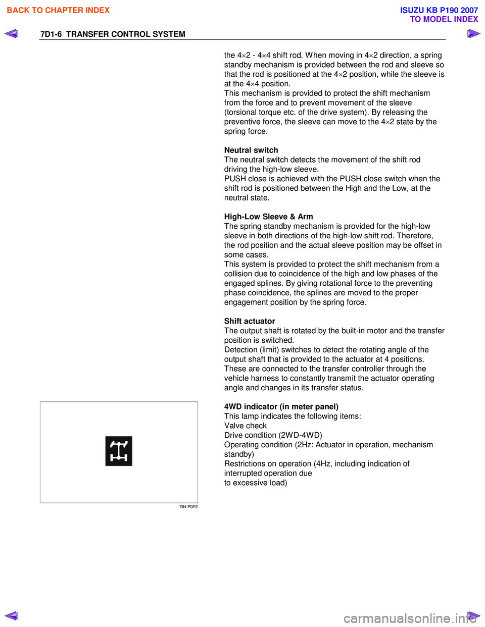
4WD indicator (in meter panel)
This lamp indicates the following items:
Valve check
Drive condition (2W D-4W D)
Operating condition (2Hz: Actuator in operation, mechanism
standby)
Restrictions on operation (4Hz, including indication of
interrupted operation due
to excessive load)
BACK TO CHAPTER INDEX
TO MODEL INDEX
ISUZU KB P190 2007
Page 4920 of 6020
7D1-46 TRANSFER CONTROL SYSTEM
Diagnosis
Before determining a trouble (Non-trouble mode)
1. When shifting from 2H to 4H:
1-1-1 When the flashing frequency of the 4WD indicator is changed from 2Hz to 4Hz (Shift on the fly) If the load is too large to shift the gears synchronously, the operation is repeated up to 3 times. If the shifting
is not effected after being repeated 3 times, the indicator frequency is changed from 2Hz to 4Hz. At the same
time, the actuator condition is changed to 2H, indicator flashes at 4Hz for 10 seconds, and then goes out.
Cause of excessive synchronous shifting load
• Extremely low temperature (the oil viscosity of the front differential increases requiring a large load for
synchronization).
• High speed (since the difference of relative revolutions of gears to be shifted synchronously is too large,
required work load per unit time becomes larger).
Step 1-1-1:
Stop the vehicle or decrease the speed and operate as required again.
1-1-2 When the flashing frequency of the 4WD indicator is changed from 2Hz to 4Hz (Rigid and free wheel
Hub) / Block out of meshing spline in transfer case.
Step 1-1-2:
Run the vehicle forward and backward several meters and operate as required again.
1-2 When the flashing of 4WD indicator at 2Hz continues more than 11.5 seconds (repetition of 3 times of
above No.1 is counted) (Shift on the fly)
If there is difference of revolutions and phases between the front wheel and the axle, connecting the front
wheel and axle is difficult.
Until shifting in the transfer and connection of the front wheel and axle are completed
∗, the indicator flashes at
a frequency of 2Hz. In the above case, the indicator continues flashing at a frequency of 2Hz until the
connection of the front axle is completed. (If the shifting in the transfer is not completed, the flashing
frequency is changed to 4Hz (above No.1).)
By correcting the difference of relative revolutions and deviation of phases, the shifting can be completed.
Step 1-2:
While the vehicle is running, check it is safe around the vehicle and then accelerate or decelerate the
vehicle while going straight.
When the vehicle is at a stop, run the vehicle forward and backward several meters.
2. When shifting from 4H to 2H
2-1 When 4WD indicator continues flashing at 2Hz
W hen shifting from 4H to 2H, the 4W D indicator continues flashing at 2Hz until separation in the transfer and
the separation of the front wheel axle are completed∗. W hen torsional torque is accumulated in the drive
system, separation in the transfer and separation of the front axle∗ is difficult. In such a case, they can be
separated by removing the torsional torque of the drive system.
Step 2-1:
While the vehicle is running, check it is safe around the vehicle and then accelerate or decelerate the
vehicle while going straight.
When the vehicle is in stop, run the vehicle several meters forward and backward.
∗: Shift on the fly only.
BACK TO CHAPTER INDEX
TO MODEL INDEX
ISUZU KB P190 2007
Page 4921 of 6020
TRANSFER CONTROL SYSTEM 7D1-47
3. Shifting from 4H to 4L
3-1 When the 4L indicator flashes at 2Hz
W hen shifting from 4H to 4L, the 4L indicator continues flashing at 2Hz until shifting in the transfer case is
completed. The phases of the engaged splines may sometimes deviate preventing completion of shifting. By
correcting the deviation of phases, shifting is completed.
Step 3-1:
(In case of AT): Set the select bar of the transmission to the D position.
(In case of MT): Set the lever of the transmission to a position allowing running and engage the clutch gently.
At this time, some rotating force acts on the engaged splines, phase is corrected and the engagement is
completed.
3-2 When the 4L indicator flashes at 2Hz for 10 seconds and then keeps ON again (AT vehicle)
This condition occurs when torsional torque has been generated between the transmission and road surface
and the transfer standby mechanism cannot absorb it completely.
Step 3-2:
Set the select lever of the transmission to the N position. (Stepping on the brake pedal is effective at
this time.)
3-3 When the 4L indicator flashes at a frequency of 4Hz
Shifting from 4H to 4L is restricted.
W hen the vehicle is running, the transmission lever is at the running range and the engine speed is high (L4:
3000rpm or more V6: 2000rpm), the transfer cannot be shifted from 4H to 4L (restriction on operation).
Restriction on operation (Except 4JA1-T)
The 4H, neutral and 4L shifting mechanism has no synchronization function. Therefore, if relative rotations in the
mechanism become excessive, shifting exerts adverse influence on the internal mechanism of the transfer. To
avoid such a trouble, vehicle condition is detected to restrict the operation (vehicle speed, engine speed and TM
position).
Requirement to restrict the speed: Vehicle should be in stop. Due to the detection logic, time to wait for start of operation may be required.
A/T: If the vehicle is in stop for a long time at the TM running range (D, 1, 2) before operating the AT, waiting
time becomes longer (from 1 second to 3 minutes at the maximum).
M/T: If the vehicle is at stop with the clutch stepped on at the T/M running position (1 – R), the time to wait
becomes longer.
W aiting time means the time commencing from when other requirements (engine speed and T/M position) are
met to permission of the speed restriction. Operation during the waiting time is not permissible.
The waiting time is 1 second at the minimum and increases up to 5 seconds if the above condition continues for
3 minutes. After that, the waiting time increases up to 3 minutes in 2 minute intervals.
W hen it is clear that the above condition has continued and reduction of waiting time is required, turn on or off
the ignition or start and stop the vehicle several meters.
Requirements for permission of restriction on engine speed: Engine speed should be decreased.
The engine speed of 3000rpm (V6: 2000rpm) or below is advisable.
Requirements for permission of restriction on T/M position restriction:
(AT) N range is recommended
(MT) should be at the neutral.
These requirements for permission should all be met before the switch is operated. If the requirements are met
after operation, operation is not automatically effected but re-operation is required after permission is given.
BACK TO CHAPTER INDEX
TO MODEL INDEX
ISUZU KB P190 2007
Page 4922 of 6020
7D1-48 TRANSFER CONTROL SYSTEM
Restriction on operation (4JA1-T)
The 4H, neutral and 4L shifting mechanism has no synchronization function. Therefore, if relative rotations in the
mechanism become excessive, shifting exerts adverse influence on the internal mechanism of the transfer. To
avoid such a trouble, vehicle condition is detected to restrict the operation (vehicle speed, and TM position).
Requirement to restrict the speed: Vehicle should be in stop.
Requirements for permission of restriction on engine speed: Engine speed should be decreased.
The engine speed of 3000rpm or below is advisable.
Requirements for permission of restriction on T/M position restriction:
should be at the neutral.
These requirements for permission should be all met before the switch is operated. If the requirements are met
after operation, operation is not automatically effected but re-operation is required after permission is given.
Note: Don’t’ accelerate engine speed a the time of this operation.
Step 3-3:
Stop the vehicle. (Close the accelerator and decrease the engine speed to below L4: 3000rpm, V6: 2000rpm.)
(In case of AT): Set the transmission select lever to the N position.
(In case of MT): Set the transmission lever to the neutral position. (Stepping on the clutch is recommended.) Push the 4L button.
If shifting operation is not completed (the lamp flashes at 2Hz), perform step 3-1.
4. Shifting from 4L to 4H
4-1 When 4L indicator continues flashing at 2Hz
W hen shifting from 4L to 4H, the 4L indicator continues flashing at 2Hz until the shifting in the transfer case is
completed. Phases of engaged splines may deviate and the operation may not be completed in some cases.
Shifting is completed by correcting the deviation of the splines.
Step 4-1: (same as step 3-1)
(In case of AT): Set the transmission select lever to the D position.
(In case of MT): Shift the transmission lever to a position allowing running and engage the clutch gently.
4-2 When the indicator continues flashing at 2Hz for 10 seconds and then keeps on at 4L again (AT
vehicle)
This condition occurs when torsional torque has been generated between the transmission and the road
surface (use of the parking position on a slope). Resistance against the separation of the driving force cannot
be completed by the waiting mechanism of the transfer.
Shifting is also possible by using the brake at the neutral position of the transmission
Step 4-2: (Same procedure as the step 3-2)
Set the transmission select lever to the N position.
(Leaving the brake lever and stepping on it again is recommended.)
4-3 When the 4L indicator flashes at 4Hz
Shifting from 4L to 4H is restricted.
W hen the vehicle is running, the transmission lever is at the running range, and the engine speed is high, the
transfer 4L cannot be shifted to 4H.
BACK TO CHAPTER INDEX
TO MODEL INDEX
ISUZU KB P190 2007
Page 4923 of 6020
TRANSFER CONTROL SYSTEM 7D1-49
Step 4-3: (Same procedure as the step 3-3)
Stop the vehicle (close the accelerator and decrease the engine speed to L4: 3000rpm V6: 2000rpm or below).
(In case of AT): Set the transmission select lever to the N position.
(In case of MT): Set the transmission lever to the neutral position (stepping on the clutch lever is recommended).
Push the 4H button.
If shifting is not complete (indicator flashes at 2Hz), go to step 4-1.
5. When shifting from 4H or 4L to neutral
(Same procedure is required when shifting from 2H but in such a case, requirements for shifting from
2H to 4H are also applied.)
5-1 Neutral indicator continues flashing at 2Hz The neutral indicator continues flashing at 2Hz until 4H (4L) is completely separated in the transfer. If torsional
torque has accumulated between the transmission and road surface, separation may be difficult.
Step 5-1:
If the operation is not complete, execute step 7 for confirmation.
(In case of AT): Set the transmission select lever to the D position. After confirming that the gears are at the neutral position, return the lever to the N
position.
(In case of MT): Set the transmission lever to a vehicle running position and engage the clutch gently. After confirming that the gears are at the neutral position, return the lever to the
neutral position
5-2 When the neutral indicator flashes at 4Hz
As in the case of shifting from 4L to 4H, restriction is imposed to the operation from 4L or 4H (including 2H). If
the transmission lever is at a running range and engine speed is high (L4: 3000rpm, V6: 2000rpm or more)
while the vehicle is running, operation from the 4L or 4H (including 2H) of the transfer to the neutral is
impossible (restriction on operation).
Step 5-2:
Stop the vehicle.
(In case of AT): Set the transmission select lever to the N (or P) position.
(In case of MT): Set the transmission lever to the neutral position (at this time, stepping on the clutch is recommended).
Keep pushing the 2H and 4L button for 10 seconds.
Follow the start procedure for confirmation. (Confirmation of drive force is not transferred; same as in
step 5-1)
After the confirmation, set the transmission to the neutral position in the case of MT or to the neutral
position in the case of AT.
BACK TO CHAPTER INDEX
TO MODEL INDEX
ISUZU KB P190 2007
Page 5079 of 6020
ELECTRICAL-BODY AND CHASSIS 8A-141
REMOVAL AND INSTALLATION
ECM (ENGINE CONTROL MODULE);
4JH1-TC
Removal
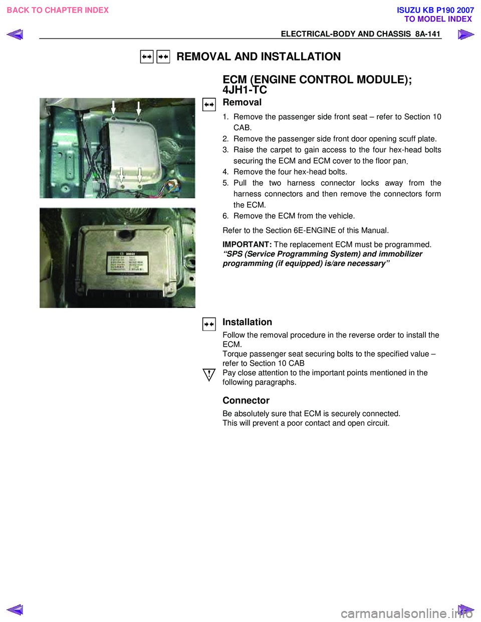
1. Remove the passenger side front seat – refer to Section 10
CAB.
2. Remove the passenger side front door opening scuff plate.
3. Raise the carpet to gain access to the four hex-head bolts securing the ECM and ECM cover to the floor pan .
4. Remove the four hex-head bolts.
5. Pull the two harness connector locks away from the harness connectors and then remove the connectors form
the ECM.
6. Remove the ECM from the vehicle.
Refer to the Section 6E-ENGINE of this Manual.
IMPORTANT: The replacement ECM must be programmed.
“SPS (Service Programming System) and immobilizer
programming (if equipped) is/are necessary”
Installation
Follow the removal procedure in the reverse order to install the
ECM.
Torque passenger seat securing bolts to the specified value –
refer to Section 10 CAB
Pay close attention to the important points mentioned in the
following paragraphs.
Connector
Be absolutely sure that ECM is securely connected.
This will prevent a poor contact and open circuit.
BACK TO CHAPTER INDEX TO MODEL INDEXISUZU KB P190 2007