Page 4747 of 6020
7B1-28 Manual Transmission (MUX)
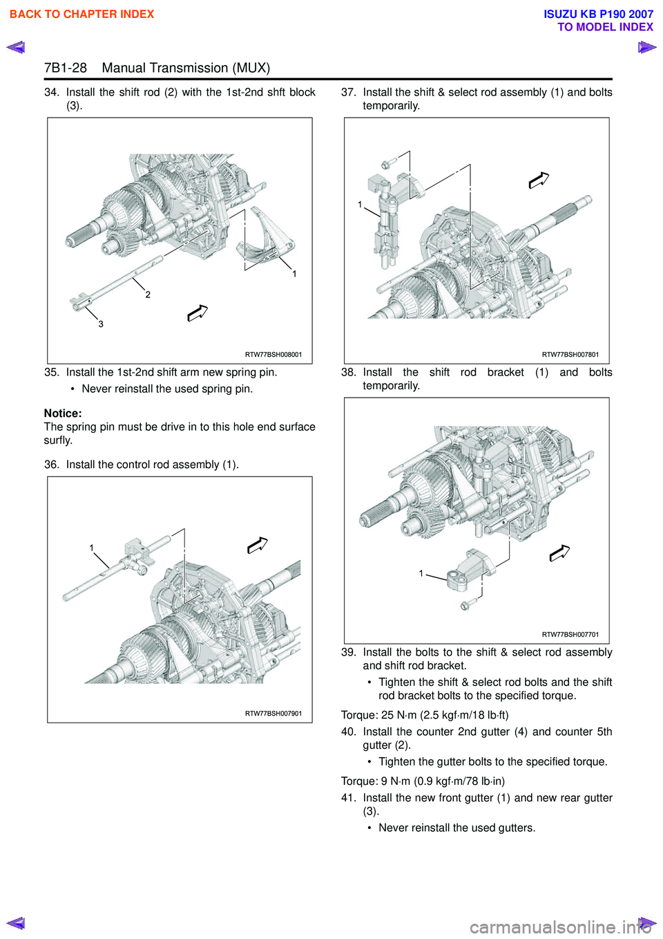
34. Install the shift rod (2) with the 1st-2nd shft block(3).
35. Install the 1st-2nd shift arm new spring pin. • Never reinstall the used spring pin.
Notice:
The spring pin must be drive in to this hole end surface
surfly.
36. Install the control rod assembly (1). 37. Install the shift & select rod assembly (1) and bolts
temporarily.
38. Install the shift rod bracket (1) and bolts temporarily.
39. Install the bolts to the shift & select rod assembly and shift rod bracket.
• Tighten the shift & select rod bolts and the shift rod bracket bolts to the specified torque.
Torque: 25 N ⋅m (2.5 kgf ⋅m/18 lb ⋅ft)
40. Install the counter 2nd gutter (4) and counter 5th gutter (2).
• Tighten the gutter bolts to the specified torque.
Torque: 9 N ⋅m (0.9 kgf ⋅m/78 lb ⋅in)
41. Install the new front gutter (1) and new rear gutter (3).
• Never reinstall the used gutters.
RTW77BSH008001
3
2
1
RTW77BSH007901
1
RTW77BSH007801
1
RTW77BSH007701
1
BACK TO CHAPTER INDEX
TO MODEL INDEX
ISUZU KB P190 2007
Page 4749 of 6020
7B1-30 Manual Transmission (MUX)
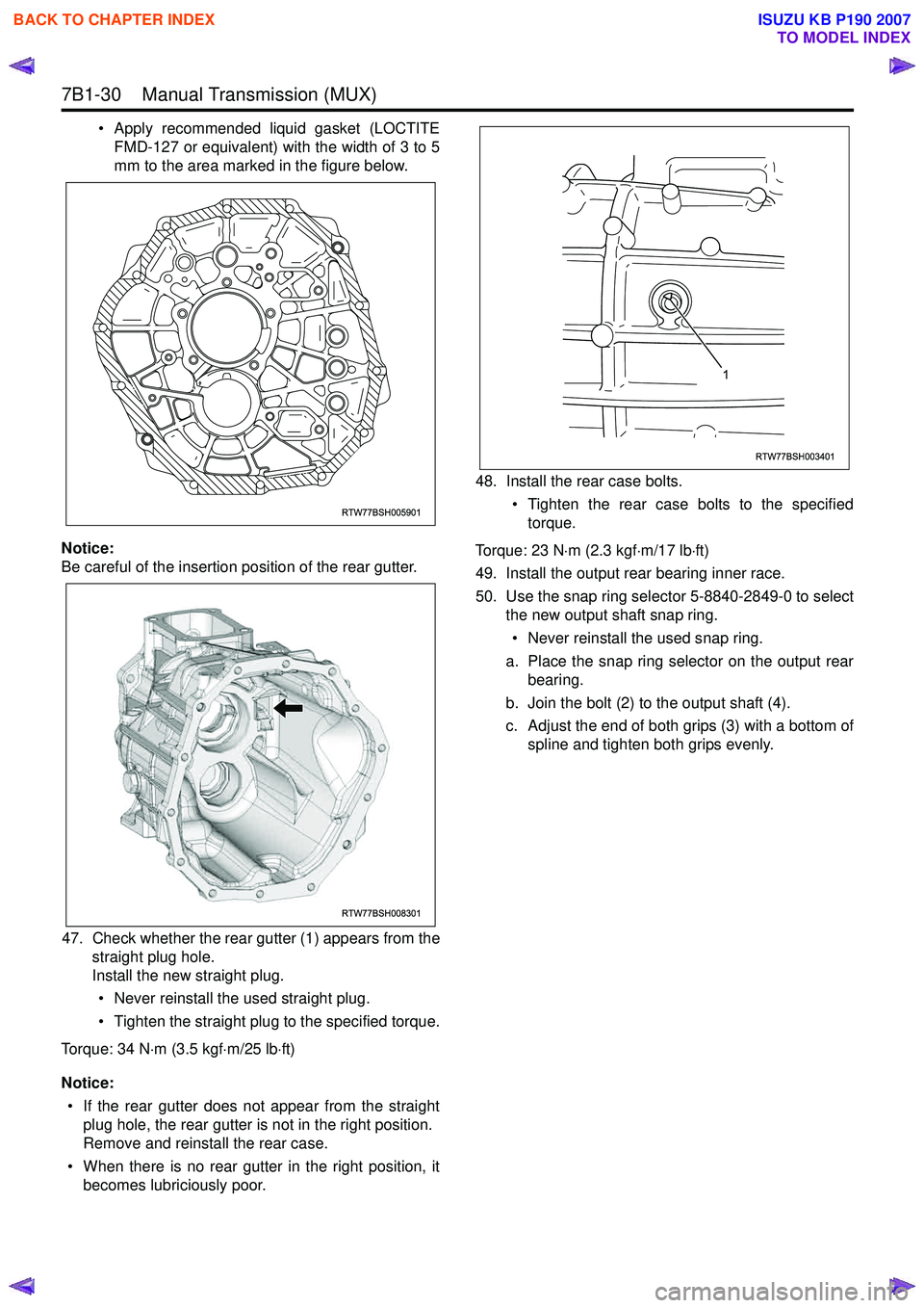
• Apply recommended liquid gasket (LOCTITEFMD-127 or equivalent) with the width of 3 to 5
mm to the area marked in the figure below.
Notice:
Be careful of the insertion position of the rear gutter.
47. Check whether the rear gutter (1) appears from the straight plug hole.
Install the new straight plug.
• Never reinstall the used straight plug.
• Tighten the straight plug to the specified torque.
Torque: 34 N ⋅m (3.5 kgf ⋅m/25 lb ⋅ft)
Notice: • If the rear gutter does not appear from the straight plug hole, the rear gutter is not in the right position.
Remove and reinstall the rear case.
• When there is no rear gutter in the right position, it becomes lubriciously poor. 48. Install the rear case bolts.
• Tighten the rear case bolts to the specifiedtorque.
Torque: 23 N ⋅m (2.3 kgf ⋅m/17 lb ⋅ft)
49. Install the output rear bearing inner race.
50. Use the snap ring selector 5-8840-2849-0 to select the new output shaft snap ring.
• Never reinstall the used snap ring.
a. Place the snap ring selector on the output rear bearing.
b. Join the bolt (2) to the output shaft (4).
c. Adjust the end of both grips (3) with a bottom of spline and tighten both grips evenly.
RTW77BSH005901
RTW77BSH008301
RTW77BSH003401
1
BACK TO CHAPTER INDEX
TO MODEL INDEX
ISUZU KB P190 2007
Page 4751 of 6020
7B1-32 Manual Transmission (MUX)
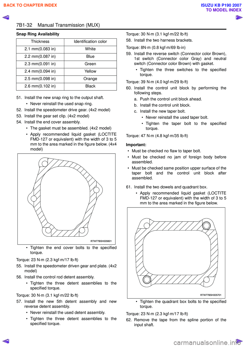
Snap Ring Availability51. Install the new snap ring to the output shaft. • Never reinstall the used snap ring.
52. Install the speedometer drive gear. (4x2 model)
53. Install the gear set clip. (4x2 model)
54. Install the end cover assembly.
• The gasket must be assembled. (4x2 model)
• Apply recommended liquid gasket (LOCTITE FMD-127 or equivalent) with the width of 3 to 5
mm to the area marked in the figure below. (4x4
model)
• Tighten the end cover bolts to the specified torque.
Torque: 23 N ⋅m (2.3 kgf ⋅m/17 lb ⋅ft)
55. Install the speedometer driven gear and plate. (4x2 model)
56. Install the control rod detent assembly.
• Tighten the three detent assemblies to thespecified torque.
Torque: 30 N ⋅m (3.1 kgf ⋅m/22 lb ⋅ft)
57. Install the new 5th detent assembly and new reverse detent assembly.
• Never reinstall the used detent assembly.
• Tighten the three detent assemblies to the specified torque. Torque: 30 N
⋅m (3.1 kgf ⋅m/22 lb ⋅ft)
58. Install the two harness brackets.
Torque: 8N ⋅m (0.8 kgf ⋅m/69 lb ⋅in)
59. Install the reverse switch (Connector color Brown), 1st switch (Connector color Gray) and neutral
switch (Connector color Brown) with gasket.
• Tighten the three switches to the specified torque.
Torque: 39 N ⋅m (4.0 kgf ⋅m/29 lb ⋅ft)
60. Install the control unit block by performing the following steps.
a. Push the control unit block ahead.
b. Install the control unit block.
c. Install the new taper bolt.
• Never reinstall the used taper bolt.
• Tighten the taper bolt to the specified torque.
Torque: 47 N ⋅m (4.8 kgf ⋅m/35 lb ⋅ft)
Important: • Must be checked no flaw to taper bolt.
• Must be checked no jam of foreign body before assembled.
• Must be checked same position upper surface of the taper bolt and the control unit block after
assembled.
61. Install the two dowels and quadrant box. • Apply recommended liquid gasket (LOCTITEFMD-127 or equivalent) with the width of 3 to 5
mm to the area marked in the figure below.
• Tighten the quadrant box bolts to the specified torque.
Torque: 23 N ⋅m (2.3 kgf ⋅m/17 lb ⋅ft)
62. Remove the tape from the spline portion of the input shaft.
Thickness
Identification color
2.1 mm(0.083 in) White
2.2 mm(0.087 in) Blue
2.3 mm(0.091 in) Green
2.4 mm(0.094 in) Yellow
2.5 mm(0.098 in) Orange
2.6 mm(0.102 in) Black
RTW77BSH005601
RTW77BSH005701
BACK TO CHAPTER INDEX
TO MODEL INDEX
ISUZU KB P190 2007
Page 4752 of 6020
Manual Transmission (MUX) 7B1-33
63. Install the front cover.• Tighten the front cover bolts to the specifiedtorque.
Torque: 23 N ⋅m (2.3 kgf ⋅m/17 lb ⋅ft)
64. After reassembling the transmission, refill the case with the new specified transmission oil.
a. Install the drain plug with new gasket. • Never reinstall the used gasket.
• Apply engine oil to the new gasket surface.
• Tighten the drain plug to the specified torque.
Torque: 39 N ⋅m (4.0 kgf ⋅m/29 lb ⋅ft)
b. Remove the filler plug with gasket.
c. Refill the case with the new specified transmission oil (BESCO Trans Axle Oil 5W-30
SF) amount 3.0 liters.
d. Install the filler plug with new gasket. • Never reinstall the used gasket.
• Apply engine oil to the new gasket surface.
• Tighten the filler plug to the specified torque.
Torque: 39 N ⋅m (4.0 kgf ⋅m/29 lb ⋅ft)
BACK TO CHAPTER INDEX
TO MODEL INDEX
ISUZU KB P190 2007
Page 4754 of 6020
Manual Transmission (MUX) 7B1-35
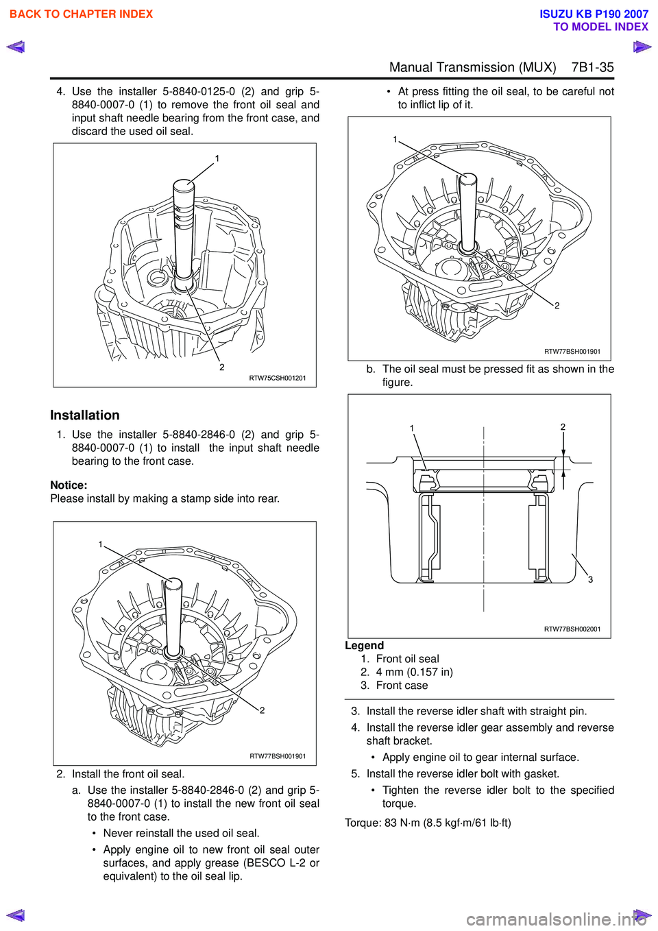
4. Use the installer 5-8840-0125-0 (2) and grip 5-8840-0007-0 (1) to remove the front oil seal and
input shaft needle bearing from the front case, and
discard the used oil seal.
Installation
1. Use the installer 5-8840-2846-0 (2) and grip 5- 8840-0007-0 (1) to install the input shaft needle
bearing to the front case.
Notice:
Please install by making a stamp side into rear.
2. Install the front oil seal. a. Use the installer 5-8840-2846-0 (2) and grip 5- 8840-0007-0 (1) to install the new front oil seal
to the front case.
• Never reinstall the used oil seal.
• Apply engine oil to new front oil seal outer surfaces, and apply grease (BESCO L-2 or
equivalent) to the oil seal lip. • At press fitting the oil seal, to be careful not
to inflict lip of it.
b. The oil seal must be pressed fit as shown in the figure.
Legend 1. Front oil seal
2. 4 mm (0.157 in)
3. Front case
3. Install the reverse idler shaft with straight pin.
4. Install the reverse idler gear assembly and reverse shaft bracket.
• Apply engine oil to gear internal surface.
5. Install the reverse idler bolt with gasket.
• Tighten the reverse idler bolt to the specifiedtorque.
Torque: 83 N ⋅m (8.5 kgf ⋅m/61 lb ⋅ft)
RTW75CSH001201
1
2
RTW77BSH001901
1 2
RTW77BSH001901
12
RTW77BSH002001
2
1
3
BACK TO CHAPTER INDEX
TO MODEL INDEX
ISUZU KB P190 2007
Page 4773 of 6020
7B1-54 Manual Transmission (MUX)
4. Install the straight pin.
5. Install the reverse inhibitor bolt.
• Tighten the reverse inhibitor bolt to thespecified torque.
Torque: 36 N ⋅m (3.7 kgf ⋅m/27 lb ⋅ft)
6. Install the reverse inhibitor and spring.
7. Install the new reverse inhibitor snap ring.
• Never reinstall the used snap ring.
Notice:
The snap ring must be assembled in groove of bolt
surely.
RTW77BSH002701
1
BACK TO CHAPTER INDEX
TO MODEL INDEX
ISUZU KB P190 2007
Page 4779 of 6020
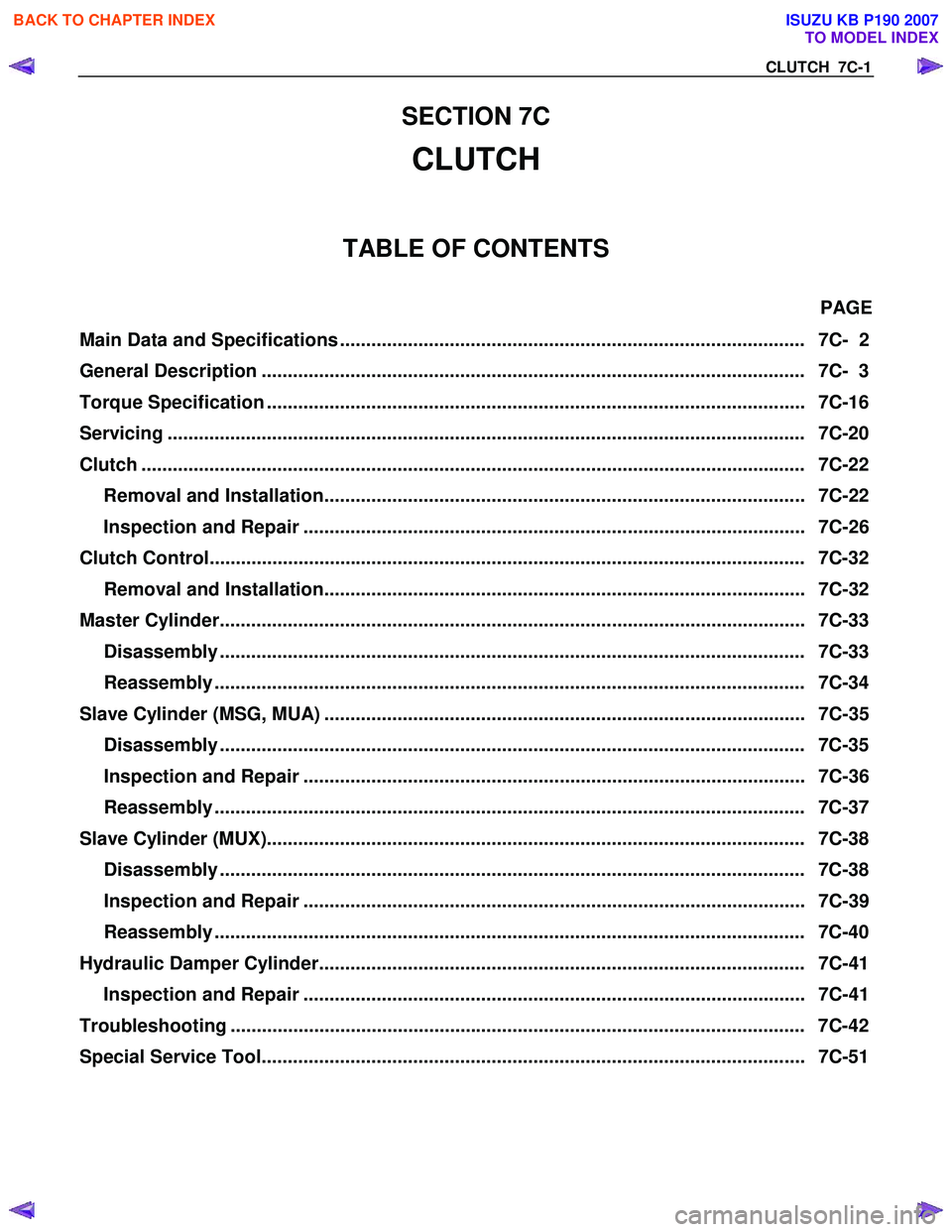
CLUTCH 7C-1
SECTION 7C
CLUTCH
TABLE OF CONTENTS
PAGE
Main Data and Specifications ......................................................................................... 7C- 2
General Description ........................................................................................................ 7C- 3
Torque Specification ....................................................................................................... 7C- 16
Servicing ...................................................................................................................... .... 7C-20
Clutch ......................................................................................................................... ...... 7C-22
Removal and Installation............................................................................................ 7C-22
Inspection and Repair ................................................................................................ 7C-26
Clutch Control................................................................................................................. . 7C-32
Removal and Installation............................................................................................ 7C-32
Master Cylinder................................................................................................................ 7C-33
Disassembly ................................................................................................................ 7C- 33
Reassembly ................................................................................................................. 7C- 34
Slave Cylinder (MSG, MUA) ............................................................................................ 7C-35 Disassembly ................................................................................................................ 7C- 35
Inspection and Repair ................................................................................................ 7C-36
Reassembly ................................................................................................................. 7C- 37
Slave Cylinder (MUX)....................................................................................................... 7C- 38
Disassembly ................................................................................................................ 7C- 38
Inspection and Repair ................................................................................................ 7C-39
Reassembly ................................................................................................................. 7C- 40
Hydraulic Damper Cylinder............................................................................................. 7C-41 Inspection and Repair ................................................................................................ 7C-41
Troubleshooting .............................................................................................................. 7 C-42
Special Service Tool........................................................................................................ 7C -51
BACK TO CHAPTER INDEX
TO MODEL INDEX
ISUZU KB P190 2007
Page 4786 of 6020
7C-8 CLUTCH
The Clutch Damper Valve is installed in the slave cylinder for MUX.
The Clutch Damper Valve delays return speed of clutch fluid when clutch is being engaged quickly at Low or
Reverse, and decreases a shock torque transmitted to drive train.
BACK TO CHAPTER INDEX
TO MODEL INDEX
ISUZU KB P190 2007