Page 4624 of 6020

7B1-18 MANUAL TRANSMISSION
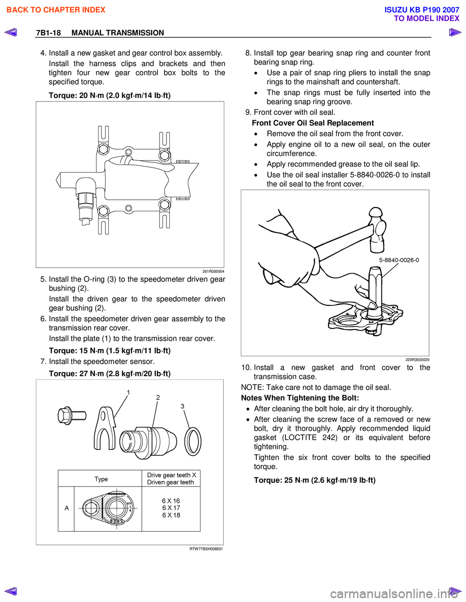
4. Install a new gasket and gear control box assembly.
Install the harness clips and brackets and then
tighten four new gear control box bolts to the
specified torque.
Torque: 20 N ⋅
⋅⋅
⋅
m (2.0 kgf ⋅
⋅⋅
⋅
m/14 lb ⋅
⋅⋅
⋅
ft)
261R300004
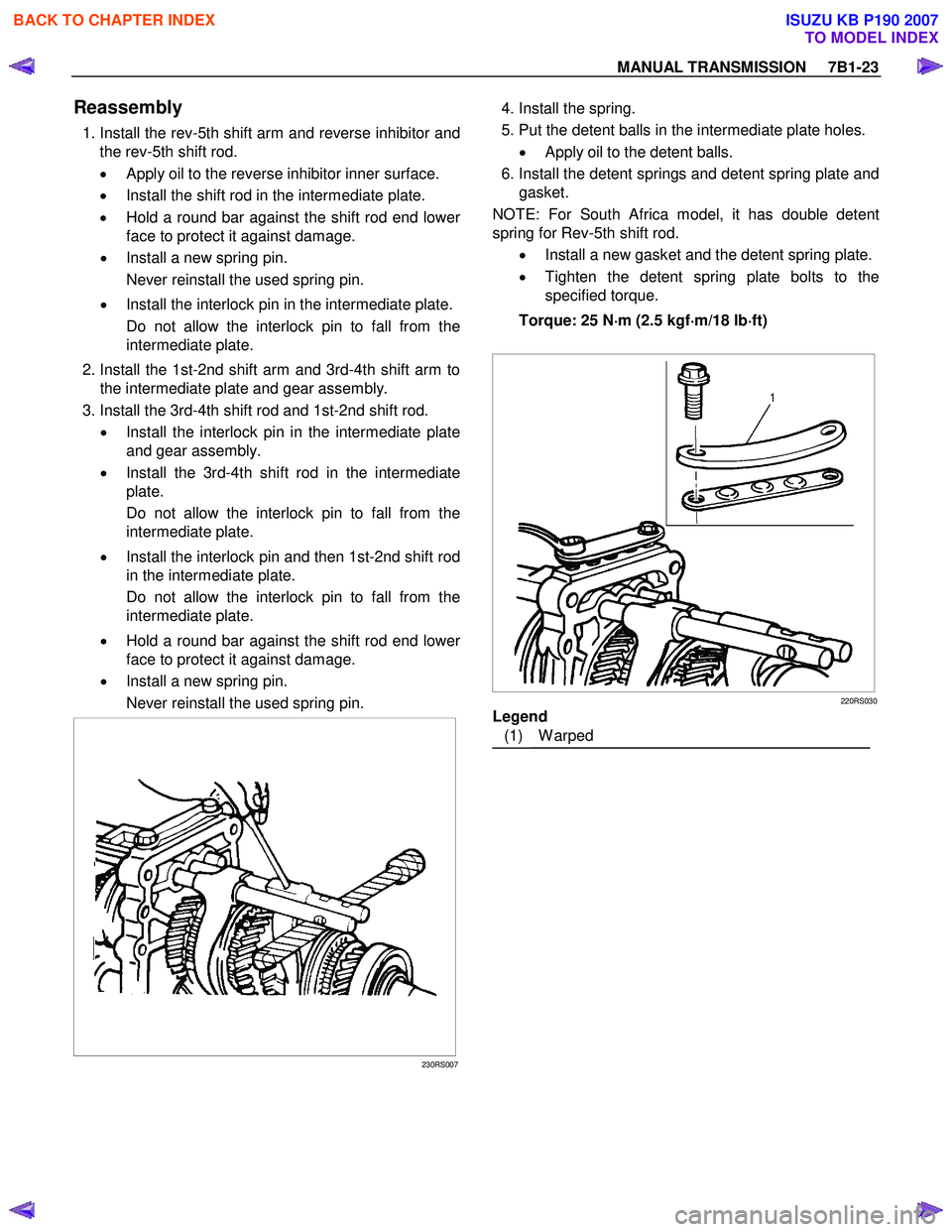
5. Install the O-ring (3) to the speedometer driven gear
bushing (2).
Install the driven gear to the speedometer driven gear bushing (2).
6. Install the speedometer driven gear assembly to the transmission rear cover.
Install the plate (1) to the transmission rear cover.
Torque: 15 N ⋅
⋅⋅
⋅
m (1.5 kgf ⋅
⋅⋅
⋅
m/11 lb ⋅
⋅⋅
⋅
ft)
7. Install the speedometer sensor.
Torque: 27 N ⋅
⋅⋅
⋅
m (2.8 kgf ⋅
⋅⋅
⋅
m/20 lb ⋅
⋅⋅
⋅
ft)
RTW 77BSH008501
8. Install top gear bearing snap ring and counter front
bearing snap ring.
• Use a pair of snap ring pliers to install the snap
rings to the mainshaft and countershaft.
• The snap rings must be fully inserted into the
bearing snap ring groove.
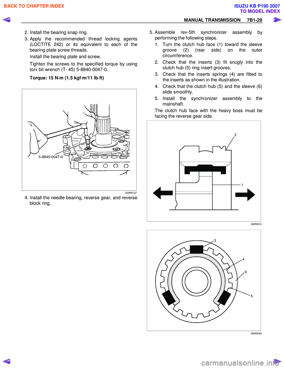
9. Front cover with oil seal. Front Cover Oil Seal Replacement • Remove the oil seal from the front cover.
• Apply engine oil to a new oil seal, on the oute
r
circumference.
• Apply recommended grease to the oil seal lip.
• Use the oil seal installer 5-8840-0026-0 to install
the oil seal to the front cover.
220R3000020
10. Install a new gasket and front cover to the transmission case.
NOTE: Take care not to damage the oil seal.
Notes When Tightening the Bolt:
• After cleaning the bolt hole, air dry it thoroughly.
•
After cleaning the screw face of a removed or new
bolt, dry it thoroughly. Apply recommended liquid
gasket (LOCTITE 242) or its equivalent before
tightening.
Tighten the six front cover bolts to the specified
torque.
Torque: 25 N ⋅
⋅⋅
⋅
m (2.6 kgf ⋅
⋅⋅
⋅
m/19 lb ⋅
⋅⋅
⋅
ft)
BACK TO CHAPTER INDEX
TO MODEL INDEX
ISUZU KB P190 2007
Page 4629 of 6020

MANUAL TRANSMISSION 7B1-23
Reassembly
1. Install the rev-5th shift arm and reverse inhibitor and
the rev-5th shift rod.
• Apply oil to the reverse inhibitor inner surface.
• Install the shift rod in the intermediate plate.
• Hold a round bar against the shift rod end lowe
r
face to protect it against damage.
• Install a new spring pin.
Never reinstall the used spring pin.
• Install the interlock pin in the intermediate plate.
Do not allow the interlock pin to fall from the
intermediate plate.
2. Install the 1st-2nd shift arm and 3rd-4th shift arm to the intermediate plate and gear assembly.
3. Install the 3rd-4th shift rod and 1st-2nd shift rod. • Install the interlock pin in the intermediate plate
and gear assembly.
• Install the 3rd-4th shift rod in the intermediate
plate.
Do not allow the interlock pin to fall from the
intermediate plate.
• Install the interlock pin and then 1st-2nd shift rod
in the intermediate plate.
Do not allow the interlock pin to fall from the
intermediate plate.
• Hold a round bar against the shift rod end lowe
r
face to protect it against damage.
• Install a new spring pin.
Never reinstall the used spring pin.
230RS007
4. Install the spring.
5. Put the detent balls in the intermediate plate holes.• Apply oil to the detent balls.
6. Install the detent springs and detent spring plate and gasket.
NOTE: For South Africa model, it has double detent
spring for Rev-5th shift rod.
• Install a new gasket and the detent spring plate.
• Tighten the detent spring plate bolts to the
specified torque.
Torque: 25 N ⋅
⋅⋅
⋅
m (2.5 kgf ⋅
⋅⋅
⋅
m/18 lb ⋅
⋅⋅
⋅
ft)
220RS030
Legend
(1) W arped
BACK TO CHAPTER INDEX
TO MODEL INDEX
ISUZU KB P190 2007
Page 4635 of 6020

MANUAL TRANSMISSION 7B1-29
2. Install the bearing snap ring.
3.
Apply the recommended thread locking agents
(LOCTITE 242) or its equivalent to each of the
bearing plate screw threads.
Install the bearing plate and screw.
Tighten the screws to the specified torque by using
torx bit wrench (T- 45) 5-8840-0047-0.
Torque: 15 N ⋅
⋅⋅
⋅
m (1.5 kgf ⋅
⋅⋅
⋅
m/11 lb ⋅
⋅⋅
⋅
ft)
220RW 137
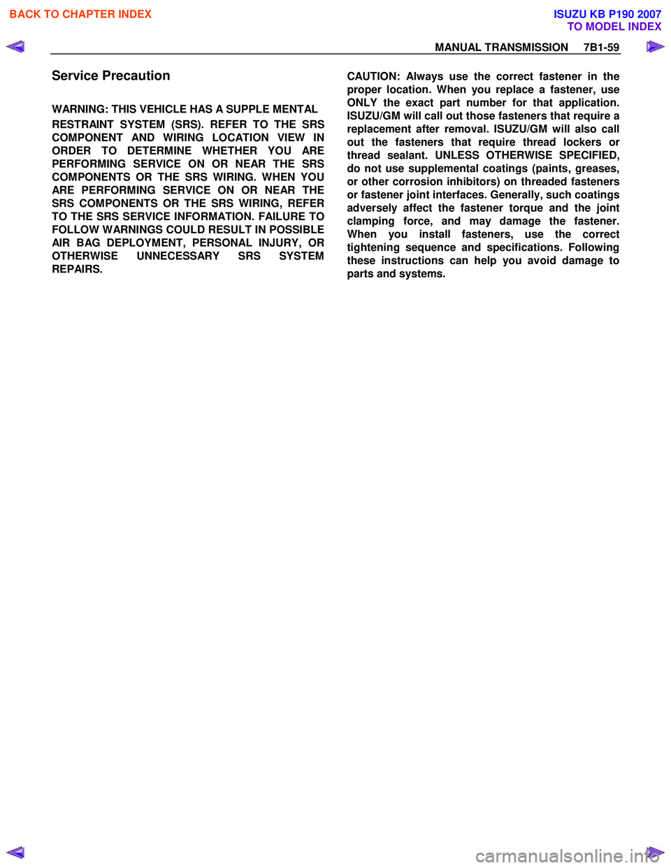
4. Install the needle bearing, reverse gear, and reverse block ring. 5. Assemble rev-5th synchronizer assembly b
y
performing the following steps.
1. Turn the clutch hub face (1) toward the sleeve groove (2) (rear side) on the oute
r
circumference.
2. Check that the inserts (3) fit snugly into the clutch hub (5) ring insert grooves.
3. Check that the inserts springs (4) are fitted to the inserts as shown in the illustration.
4. Check that the clutch hub (5) and the sleeve (6) slide smoothly.
5. Install the synchronizer assembly to the mainshaft.
The clutch hub face with the heavy boss must be
facing the reverse gear side.
226RS013
226RS049
BACK TO CHAPTER INDEX
TO MODEL INDEX
ISUZU KB P190 2007
Page 4636 of 6020
7B1-30 MANUAL TRANSMISSION
6. Mesh the 1st-2nd and 3rd-4th synchronizers with
both the 1st and 3rd gears (double engagement).
226RS015
This will prevent the mainshaft from turning.
7. Install the new mainshaft hub nut. Use the mainshaft nut wrench 5-8840-2156-0 to
tighten the mainshaft nut to the specified torque.
Torque: 137 N ⋅
⋅⋅
⋅
m (14.0 kgf ⋅
⋅⋅
⋅
m/101 lb ⋅
⋅⋅
⋅
ft)
226RW 214
8. Use a punch to stake the mainshaft nut.
226RW 153
9. Install the needle bearing, 5th block ring, and 5th gear.
10.
Apply engine oil to the counter reverse gear and the
reverse gear.
Install the counter reverse gear to the counter shaft.
The reverse gear projection must be facing the
intermediate plate.
226RW 151
BACK TO CHAPTER INDEX
TO MODEL INDEX
ISUZU KB P190 2007
Page 4654 of 6020
7B1-48 MANUAL TRANSMISSION
Torque Specifications
N⋅
⋅⋅
⋅
m (kgf ⋅
⋅⋅
⋅
m/lb ⋅
⋅⋅
⋅
ft)
RTW 77BLF003401
About arrow mark, refer to Transmission (MUA) Installation in this section.
BACK TO CHAPTER INDEX
TO MODEL INDEX
ISUZU KB P190 2007
Page 4655 of 6020
MANUAL TRANSMISSION 7B1-49
Torque Specifications (Cont'd)
N⋅
⋅⋅
⋅
m (kgf ⋅
⋅⋅
⋅
m/lb ⋅
⋅⋅
⋅
ft)
RTW 77BLF003501
BACK TO CHAPTER INDEX
TO MODEL INDEX
ISUZU KB P190 2007
Page 4656 of 6020
7B1-50 MANUAL TRANSMISSION
Torque Specifications (Cont'd)
N⋅
⋅⋅
⋅
m (kgf ⋅
⋅⋅
⋅
m/lb ⋅
⋅⋅
⋅
ft)
RTW 57BLF000301
BACK TO CHAPTER INDEX
TO MODEL INDEX
ISUZU KB P190 2007
Page 4665 of 6020

MANUAL TRANSMISSION 7B1-59
Service Precaution
WARNING: THIS VEHICLE HAS A SUPPLE MENTAL
RESTRAINT SYSTEM (SRS). REFER TO THE SRS
COMPONENT AND WIRING LOCATION VIEW IN
ORDER TO DETERMINE WHETHER YOU ARE
PERFORMING SERVICE ON OR NEAR THE SRS
COMPONENTS OR THE SRS WIRING. WHEN YOU
ARE PERFORMING SERVICE ON OR NEAR THE
SRS COMPONENTS OR THE SRS WIRING, REFER
TO THE SRS SERVICE INFORMATION. FAILURE TO
FOLLOW WARNINGS COULD RESULT IN POSSIBLE
AIR BAG DEPLOYMENT, PERSONAL INJURY, OR
OTHERWISE UNNECESSARY SRS SYSTEM
REPAIRS.
CAUTION: Always use the correct fastener in the
proper location. When you replace a fastener, use
ONLY the exact part number for that application.
ISUZU/GM will call out those fasteners that require a
replacement after removal. ISUZU/GM will also call
out the fasteners that require thread lockers o
r
thread sealant. UNLESS OTHERWISE SPECIFIED,
do not use supplemental coatings (paints, greases,
or other corrosion inhibitors) on threaded fasteners
or fastener joint interfaces. Generally, such coatings
adversely affect the fastener torque and the joint
clamping force, and may damage the fastener.
When you install fasteners, use the correct
tightening sequence and specifications. Following
these instructions can help you avoid damage to
parts and systems.
BACK TO CHAPTER INDEX
TO MODEL INDEX
ISUZU KB P190 2007