Page 4559 of 6020
7A4-82 UNIT REPAIR (JR405E)
Torque: 6 N⋅
⋅⋅
⋅
m (0.6 kgf ⋅
⋅⋅
⋅
m/52 lb ⋅
⋅⋅
⋅
in)
• Remove the holding fixture from the transmission case.
RTW 47ASH001001
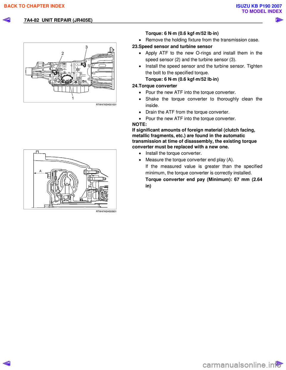
23.Speed sensor and turbine sensor
• Apply ATF to the new O-rings and install them in the
speed sensor (2) and the turbine sensor (3).
• Install the speed sensor and the turbine sensor. Tighten
the bolt to the specified torque.
Torque: 6 N ⋅
⋅⋅
⋅
m (0.6 kgf ⋅
⋅⋅
⋅
m/52 Ib ⋅
⋅⋅
⋅
in)
24.Torque converter • Pour the new ATF into the torque converter.
• Shake the torque converter to thoroughly clean the
inside.
• Drain the ATF from the torque converter.
• Pour the new ATF into the torque converter.
NOTE:
If significant amounts of foreign material (clutch facing,
metallic fragments, etc.) are found in the automatic
transmission at time of disassembly, the existing torque
converter must be replaced with a new one.
RTW 47ASH000901
•
Install the torque converter.
• Measure the torque converter end play (A).
If the measured value is greater than the specified
minimum, the torque converter is correctly installed.
Torque converter end pay (Minimum): 67 mm (2.64
in)
BACK TO CHAPTER INDEX
TO MODEL INDEX
ISUZU KB P190 2007
Page 4561 of 6020
7A4-84 UNIT REPAIR (JR405E)
SERVICE STANDARD (Cont’d)
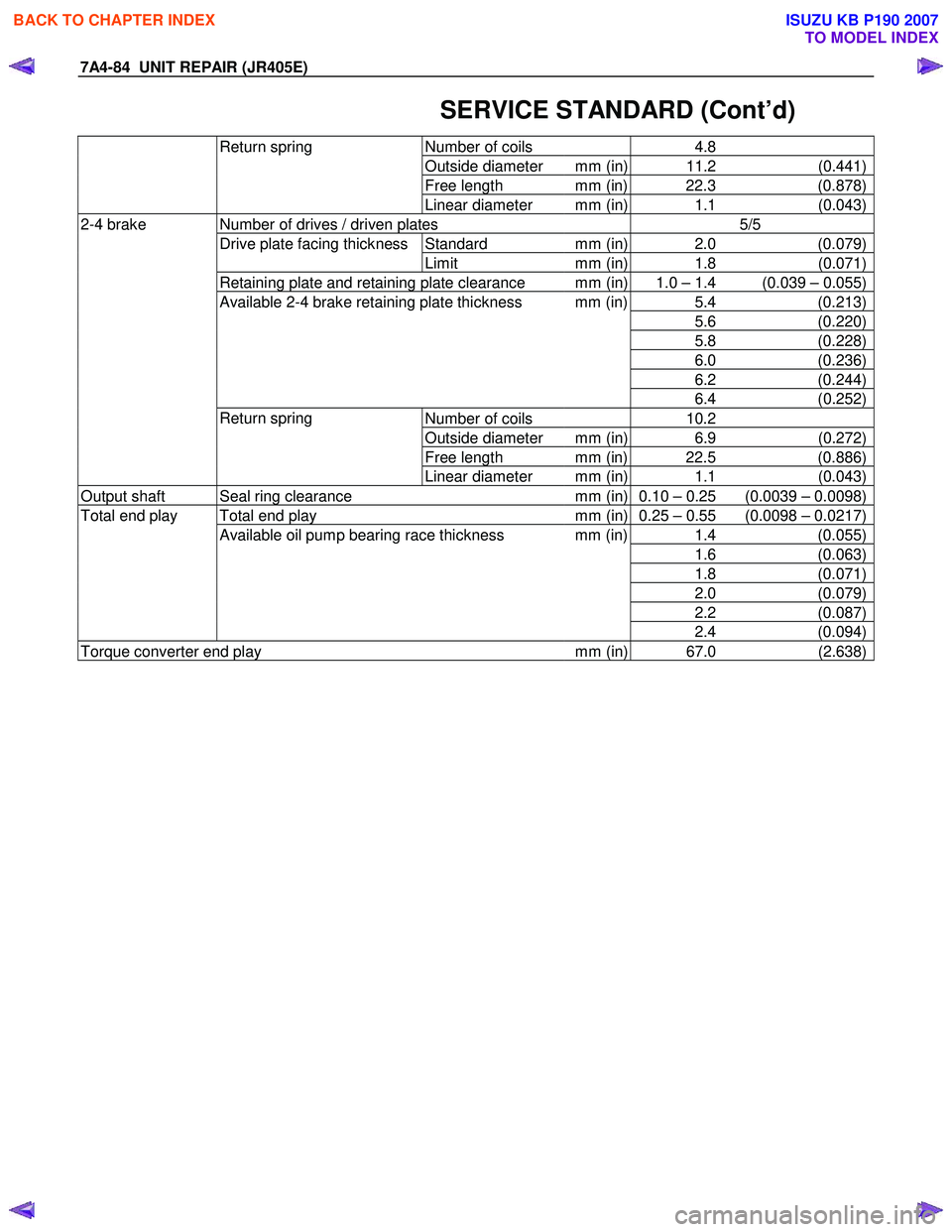
Number of coils 4.8
Outside diameter mm (in) 11.2 (0.441)
Free length mm (in) 22.3 (0.878)
Return spring
Linear diameter mm (in) 1.1 (0.043)
Number of drives / driven plates 5/5
Standard mm (in) 2.0 (0.079)Drive plate facing thickness
Limit mm (in) 1.8 (0.071)
Retaining plate and retaining plate clearance mm (in) 1.0 – 1.4 (0.039 – 0.055)
5.4 (0.213)
5.6 (0.220)
5.8 (0.228)
6.0 (0.236)
6.2 (0.244)
Available 2-4 brake retaining plate thickness mm (in)
6.4 (0.252)
Number of coils 10.2
Outside diameter mm (in) 6.9 (0.272)
Free length mm (in) 22.5 (0.886)
2-4 brake
Return spring Linear diameter mm (in) 1.1 (0.043)
Output shaft Seal ring clearance mm (in) 0.10 – 0.25 (0.0039 – 0.0098)
Total end play mm (in) 0.25 – 0.55 (0.0098 – 0.0217)
1.4 (0.055)
1.6 (0.063)
1.8 (0.071)
2.0 (0.079)
2.2 (0.087)
Total end play
Available oil pump bearing race thickness mm (in)
2.4 (0.094)
Torque converter end play mm (in) 67.0 (2.638)
BACK TO CHAPTER INDEX
TO MODEL INDEX
ISUZU KB P190 2007
Page 4565 of 6020
MSG MODEL 7B-1
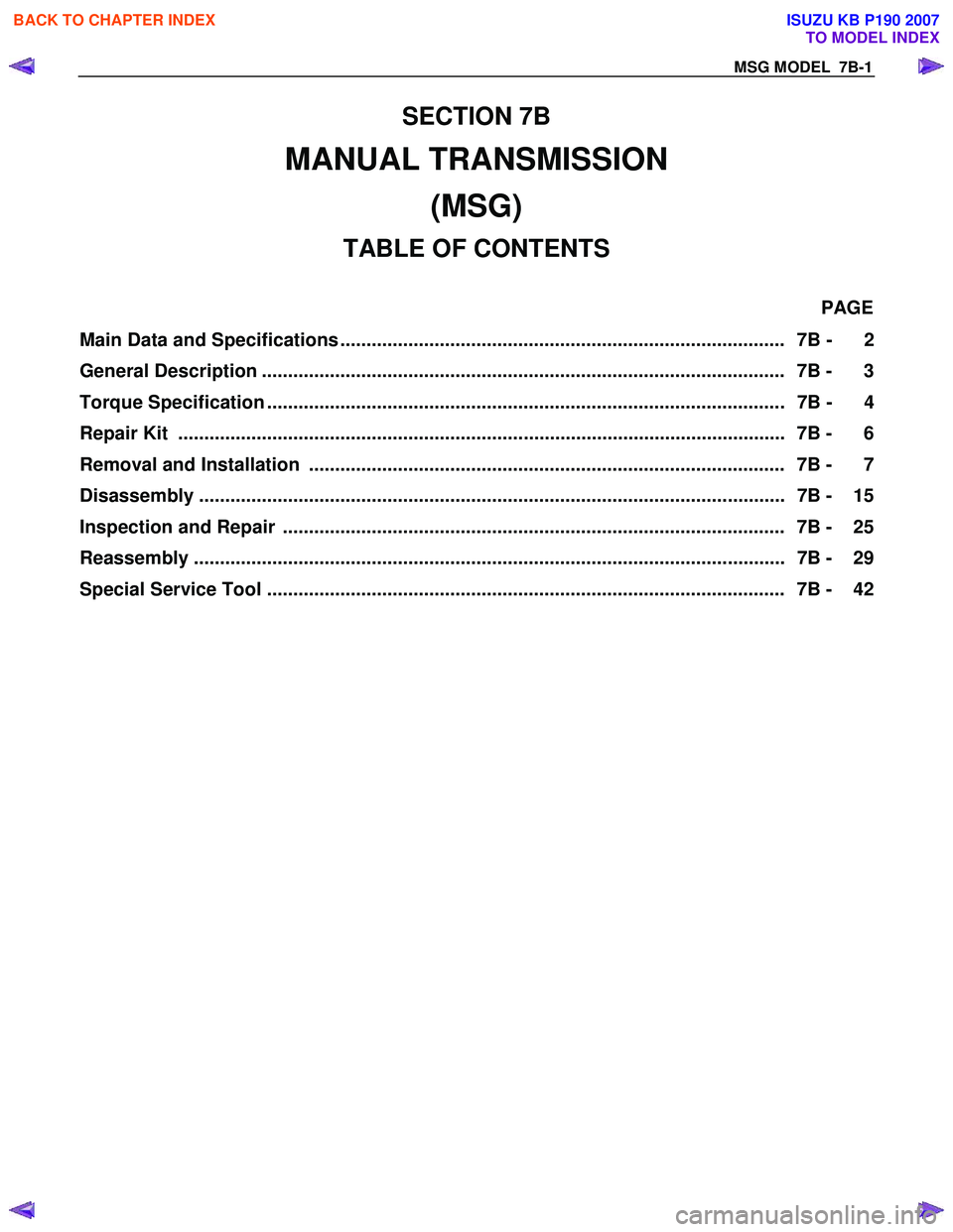
SECTION 7B
MANUAL TRANSMISSION (MSG)
TABLE OF CONTENTS
PAGE
Main Data and Specifications ..................................................................................... 7B - 2
General Description .................................................................................................... 7B - 3
Torque Specification ................................................................................................... 7B - 4
Repair Kit .................................................................................................................... 7B - 6
Removal and Installation ........................................................................................... 7B - 7
Disassembly ................................................................................................................ 7B - 15
Inspection and Repair ................................................................................................ 7B - 25
Reassembly ................................................................................................................. 7B - 29
Special Service Tool ................................................................................................... 7B - 42
BACK TO CHAPTER INDEX
TO MODEL INDEX
ISUZU KB P190 2007
Page 4568 of 6020
7B-4 MSG MODEL
TORQUE SPECIFICATION
STANDDARD BOLTS
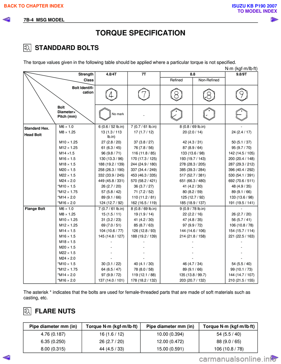
The torque values given in the following table should be applied where a particular torque is not specified.
N⋅m (kgf ⋅m/lb ⋅ft)
Strength 4.8/4T 7T 8.8 9.8/9T
Class Refined Non-Refined
Bolt Identifi-
cation
Bolt
Diameter ×
××
×
Pitch (mm)
No mark-
M6 × 1.0 6 (0.6 / 52 lb.in) 7 (0.7 / 61 lb.in) 8 (0.8 / 69 lb.in) -
M8 × 1.25 13 (1.3 / 113
lb.in) 17 (1.7 / 12)
20 (2.0 / 14) 24 (2.4 / 17)
M10 × 1.25 27 (2.8 / 20) 37 (3.8 / 27) 42 (4.3 / 31) 50 (5.1 / 37)
M12 × 1.25 61 (6.3 / 45) 76 (7.8 / 56) 87 (8.9 / 64) 95 (9.7 / 70)
M14 ×1.5 96 (9.8 / 71) 116 (11.8 / 85) 133 (13.6 / 98) 142 (14.5 / 105)
M16 × 1.5 130 (13.3 / 96) 170 (17.3 / 125) 193 (19.7 / 143) 200 (20.4 / 148)
M18 × 1.5 188 (19.2 / 139) 244 (24.9 / 180) 278 (28.3 / 205) 287 (29.3 / 212)
M20 × 1.5 258 (26.3 / 190) 337 (34.4 / 249) 385 (39.3 / 284) 396 (40.4 / 292)
M22 × 1.5 332 (33.9 / 245) 453 (46.3 / 335) 517 (52.7 / 381) 530 (54.1 / 391)
M24 × 2.0 449 (45.8 / 331) 570 (58.2 / 421) 651 (66.3 / 480) 692 (70.6 / 511)
* M10 × 1.5 26 (2.7 / 20) 36 (3.7 / 27) 41 (4.2 / 30) 48 (4.9 / 35)
* M12 × 1.75 57 (5.8 / 42) 71 (7.2 / 52) 80 (8.2 / 59) 89 (9.1 / 66)
* M14 × 2.0 89 (9.1 / 66) 110 (11.2 / 81) 125 (12.7 / 92) 133 (13.6 / 98)
* M16 × 2.0 124 (12.7 / 92) 162 (16.5 / 119) 185 (18.9 / 137) 191 (19.5 / 141)
Flange Bolt M6 × 1.0 7 (0.7 / 61 lb.in) 8 (0.8 / 69 lb.in) 9 (0.9 / 78 lb.in) -
M8 × 1.25 15 (1.5 / 11) 19 (1.9 / 14) 22 (2.2 / 16) 26 (2.7 / 20)
M10 × 1.25 31 (3.2 / 23) 41 (4.2 / 30) 47 (4.8 / 35) 56 (5.7 / 41)
M12 × 1.25 69 (7.0 / 51) 85 (8.7 / 63) 97 (9.9 / 72) 106 (10.8 / 78)
M14 × 1.5 104 (10.6 / 77) 126 (12.8 / 93) 144 (14.6 / 106) 154 (15.7 / 114)
M16 × 1.5 145 (14.8 / 127) 188 (19.2 / 139) 214 (21.8 / 158) 221 (22.5 / 163)
M18 × 1.5 - - - -
M20 × 1.5 - - - -
M22 × 1.5 - - - -
M24 × 2.0 - - - -
* M10 × 1.5 30 (3.1 / 22) 40 (4.1 / 30) 46 (4.7 / 34) 54 (5.5 / 40)
* M12 × 1.75 64 (6.5 / 47) 78 (8.0 / 58) 89 (9.1 / 66) 99 (10.1 / 73)
* M14 × 2.0 97 (9.9 / 72) 119 (12.1 / 88) 135 (13.8 / 99.7) 144 (14.7 / 107)
* M16 × 2.0 137 (14.0 / 101) 178 (18.2 / 132) 203 (20.7 / 132) 210 (21.5 / 155)
The asterisk * indicates that the bolts are used for female-threaded parts that are made of soft materials such as
casting, etc.
FLARE NUTS
Pipe diameter mm (in) Torque N ⋅
⋅⋅
⋅
m (kgf ⋅
⋅⋅
⋅
m/lb ⋅
⋅⋅
⋅
ft) Pipe diameter mm (in) Torque N ⋅
⋅⋅
⋅
m (kgf ⋅
⋅⋅
⋅
m/lb ⋅
⋅⋅
⋅
ft)
4.76 (0.187) 16 (1.6 / 12) 10.00 (0.394) 54 (5.5 / 40)
6.35 (0.250) 26 (2.7 / 20) 12.00 (0.472) 88 (9.0 / 65)
8.00 (0.315) 44 (4.5 / 33) 15.00 (0.591) 106 (10.8 / 78)
Standard Hex.
Head Bolt
BACK TO CHAPTER INDEX
TO MODEL INDEX
ISUZU KB P190 2007
Page 4576 of 6020
7B-12 MSG MODEL
N⋅
⋅⋅
⋅
m (kgf ⋅
⋅⋅
⋅
m/lb ⋅
⋅⋅
⋅
ft)
mm (in)
RTW 77BLF004201
10. Install the rear mounting rubber 3 to the transmission 2.
Install the rear mounting rubber
3 to the No.3
crossmember
4.
11. Tighten the rear mounting rubber nuts
1 to the specified
forque.
Rear Mounting Rubber Nut Torque N⋅m (kgf ⋅m/lb ⋅ft)
41 (4.2 / 30)
Mounting Bolt Torgue N⋅m (kgf ⋅m/lb ⋅ft)
41 (4.2 / 30)
BACK TO CHAPTER INDEX
TO MODEL INDEX
ISUZU KB P190 2007
Page 4577 of 6020
MSG MODEL 7B-13
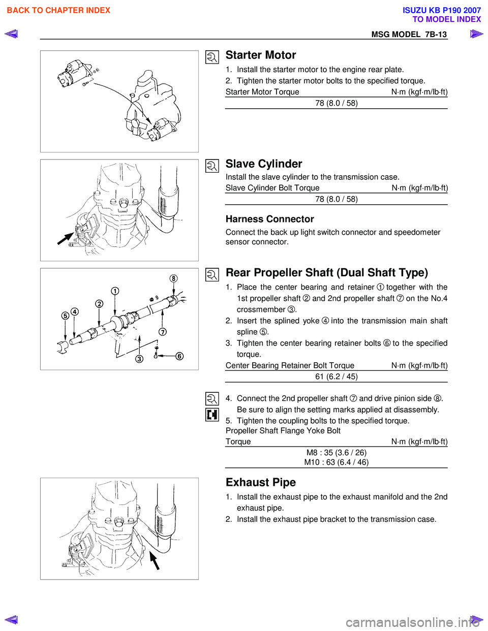
Starter Motor
1. Install the starter motor to the engine rear plate.
2. Tighten the starter motor bolts to the specified torque.
Starter Motor Torque N⋅m (kgf ⋅m/lb ⋅ft)
78 (8.0 / 58)
Slave Cylinder
Install the slave cylinder to the transmission case.
Slave Cylinder Bolt Torque N ⋅m (kgf ⋅m/lb ⋅ft
)
78 (8.0 / 58)
Harness Connector
Connect the back up light switch connector and speedometer
sensor connector.
Rear Propeller Shaft (Dual Shaft Type)
1. Place the center bearing and retainer 1 together with the
1st propeller shaft
2 and 2nd propeller shaft 7on the No.4
crossmember
3.
2. Insert the splined yoke
4 into the transmission main shaft
spline
5.
3. Tighten the center bearing retainer bolts
6 to the specified
torque.
Center Bearing Retainer Bolt Torque N ⋅m (kgf ⋅m/lb ⋅ft)
61 (6.2 / 45)
4. Connect the 2nd propeller shaft
7 and drive pinion side 8.
Be sure to align the setting marks applied at disassembly.
5. Tighten the coupling bolts to the specified torque.
Propeller Shaft Flange Yoke Bolt
Torque N ⋅m (kgf ⋅m/lb ⋅ft)
M8 : 35 (3.6 / 26)
M10 : 63 (6.4 / 46)
Exhaust Pipe
1. Install the exhaust pipe to the exhaust manifold and the 2nd
exhaust pipe.
2. Install the exhaust pipe bracket to the transmission case.
BACK TO CHAPTER INDEX
TO MODEL INDEX
ISUZU KB P190 2007
Page 4578 of 6020
7B-14 MSG MODEL
Gear Shift Lever
1. Replenish the transmission case with the specified engineoil.
Transmission Case Oil lit(US gal.)
1.55 (0.41)
2. Install the gear shift lever to the gear control box.
3. Tighten the gear shift lever cover bolts to the specified torque.
Shift Lever Cover Bolt Torque N⋅m(kgf ⋅m/lb ⋅ft)
20 (2.0 / 14)
4. Install the dust cover and the grommet.
5. Install the front console assembly.
6. Install the gear shift lever knob.
Lowering the Vehicle
1. Place a jack beneath the vehicle.
2. Raise the jack to remove the chassis stands.
3. Lower the vehicle to the ground.
Engine Hood
Align the setting marks(applied at removal)on the engine hood
and the engine hood hinges to install the engine hood.
Battery Cable
Connect the negative (-) cable to the battery terminal.
BACK TO CHAPTER INDEX
TO MODEL INDEX
ISUZU KB P190 2007
Page 4599 of 6020
MSG MODEL 7B-35
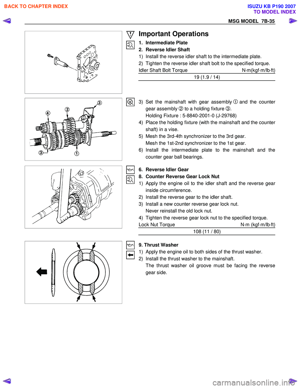
Important Operations
1. Intermediate Plate
2. Reverse Idler Shaft
1) Install the reverse idler shaft to the intermediate plate.
2) Tighten the reverse idler shaft bolt to the specified torque.
Idler Shaft Bolt Torque N⋅m(kgf ⋅m/lb ⋅ft)
19 (1.9 / 14)
3) Set the mainshaft with gear assembly
1 and the counter
gear assembly
2 to a holding fixture
3.
Holding Fixture : 5-8840-2001-0 (J-29768)
4) Place the holding fixture (with the mainshaft and the counte
r
shaft) in a vise.
5) Mesh the 3rd-4th synchronizer to the 3rd gear.
Mesh the 1st-2nd synchronizer to the 1st gear.
6) Install the intermediate plate to the mainshaft and the counter gear ball bearings.
6. Reverse Idler Gear
8. Counter Reverse Gear Lock Nut
1) Apply the engine oil to the idler shaft and the reverse gear
inside circumference.
2) Install the reverse gear to the idler shaft.
3) Install a new counter reverse gear lock nut.
Never reinstall the old lock nut.
4) Tighten the reverse gear lock nut to the specified torque.
Lock Nut Torque N⋅m (kgf ⋅m/lb ⋅ft)
108 (11 / 80)
9. Thrust Washer
1) Apply the engine oil to both sides of the thrust washer.
2) Install the thrust washer to the mainshaft.
The thrust washer oil groove must be facing the reverse gear side.
BACK TO CHAPTER INDEX
TO MODEL INDEX
ISUZU KB P190 2007