2007 ISUZU KB P190 engine
[x] Cancel search: enginePage 1543 of 6020
6C-2 FUEL SYSTEM (4JK1/4JJ1)
Fuel System
Service Precautions
Parts of the fuel system such as the internal part of the
fuel injector, and holes and clearances that form
passages for fuel are finished to a very high degree o
f
accuracy. They are therefore highly sensitive to foreign
matter and the entry of foreign matter could cause
damage to the fuel passage. Therefore, effective
measures should be taken to prevent the entry o
f
foreign matter.
If a water removal agent is used in the fuel then it will
absorb moisture in the light oil and may cause rust.
Therefore, do not use a water removal agent in the fuel
tank.
W hen servicing the fuel system, every precaution must
be taken to prevent the entry of foreign material into the
system.
• Before beginning the service procedure, wash the
fuel line and the surrounding area.
• Perform the service procedures with clean hands.
Do not wear work gloves.
• Immediately after removing the fuel hose and/o
r
fuel pipe, carefully tape vinyl bags over the
exposed ends of the hose or pipe.
• If parts are to be replaced (fuel hose, fuel pipe,
etc.) do not open the new part packaging until
installation.
Discard gaskets and O-rings and replace them with ne
w
ones.
Work procedure
•
The fuel opening must be quickly sealed when
removing the fuel pipe, injection pipe, fuel injector,
fuel supply pump, and fuel rail.
• The eyebolts and gasket must be stored in a clean
parts box with a lid to prevent adhesion of foreign
matter.
• Fuel leakage could cause fires. Therefore, afte
r
finishing the work, wipe off the fuel that has leaked
out and make sure there is no fuel leakage afte
r
starting the engine.
BACK TO CHAPTER INDEX
TO MODEL INDEX
ISUZU KB P190 2007
Page 1547 of 6020
6C-6 FUEL SYSTEM (4JK1/4JJ1)
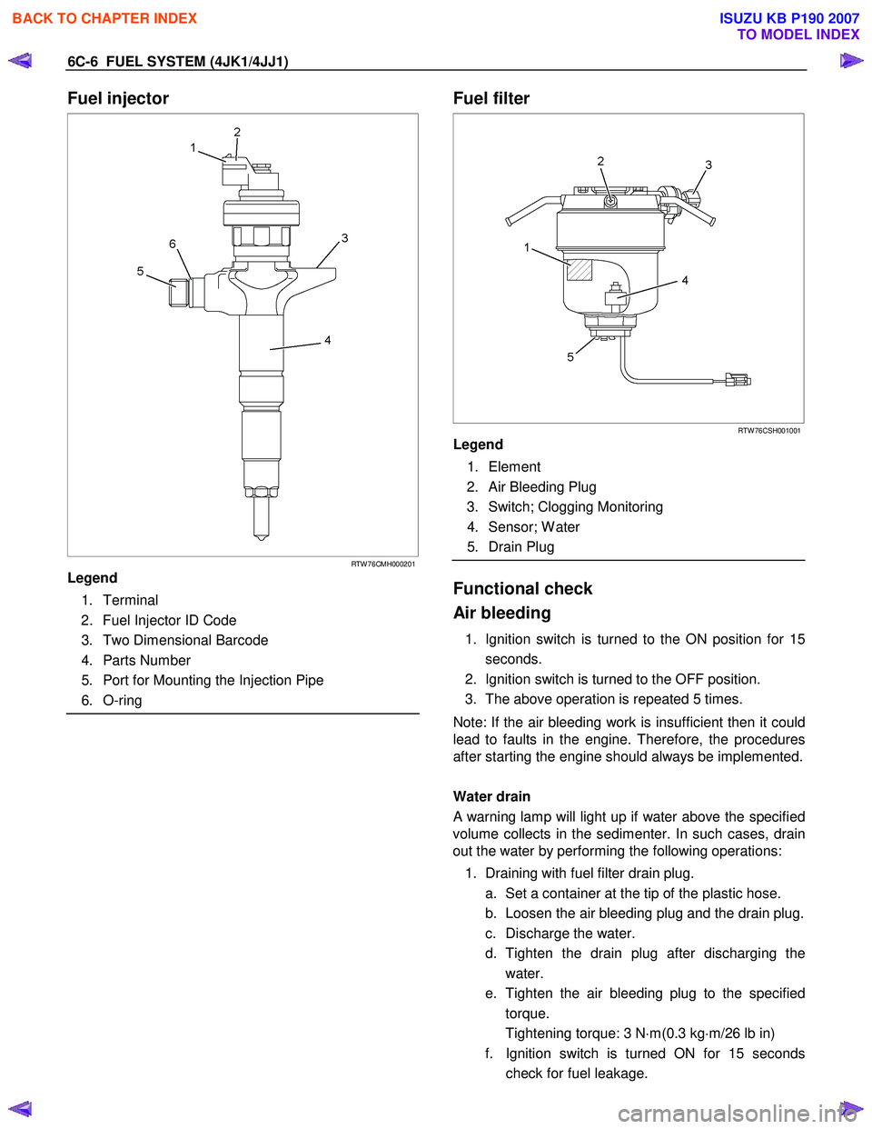
Fuel injector
RTW 76CMH000201
Legend
1. Terminal
2. Fuel Injector ID Code
3. Two Dimensional Barcode
4. Parts Number
5. Port for Mounting the Injection Pipe
6. O-ring
Fuel filter
RTW 76CSH001001
Legend
1. Element
2. Air Bleeding Plug
3. Switch; Clogging Monitoring
4. Sensor; W ater
5. Drain Plug
Functional check
Air bleeding
1. Ignition switch is turned to the ON position for 15 seconds.
2. Ignition switch is turned to the OFF position.
3. The above operation is repeated 5 times.
Note: If the air bleeding work is insufficient then it could
lead to faults in the engine. Therefore, the procedures
after starting the engine should always be implemented.
Water drain
A warning lamp will light up if water above the specified
volume collects in the sedimenter. In such cases, drain
out the water by performing the following operations:
1. Draining with fuel filter drain plug. a. Set a container at the tip of the plastic hose.
b. Loosen the air bleeding plug and the drain plug.
c. Discharge the water.
d. Tighten the drain plug after discharging the water.
e. Tighten the air bleeding plug to the specified torque.
Tightening torque: 3 N ⋅m(0.3 kg ⋅m/26 lb in)
f. Ignition switch is turned ON for 15 seconds check for fuel leakage.
BACK TO CHAPTER INDEX
TO MODEL INDEX
ISUZU KB P190 2007
Page 1548 of 6020
FUEL SYSTEM (4JK1/4JJ1) 6C-7
g. Check that the warning lamp in the meter is off.
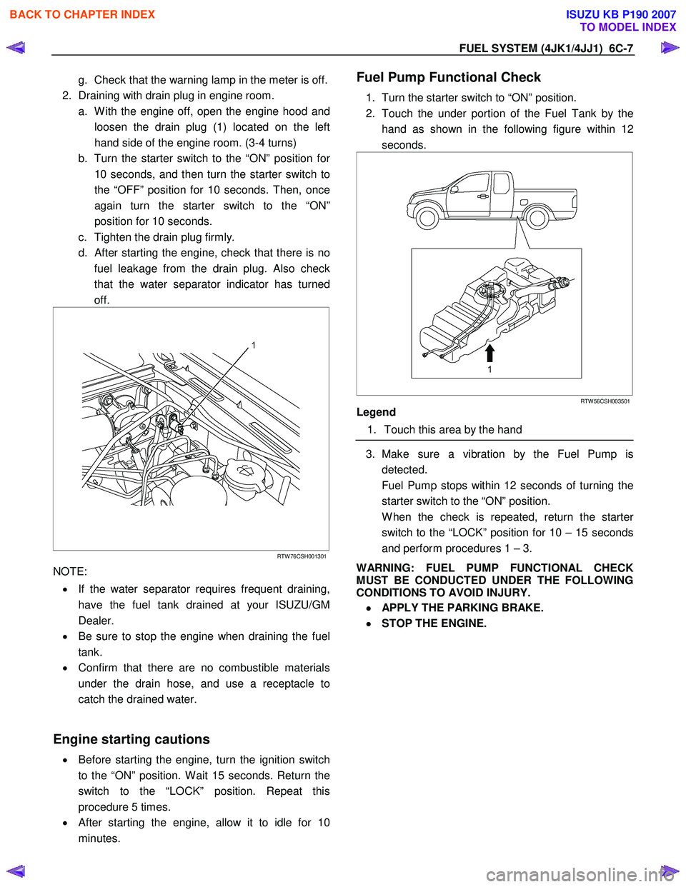
2. Draining with drain plug in engine room. a. W ith the engine off, open the engine hood and loosen the drain plug (1) located on the left
hand side of the engine room. (3-4 turns)
b. Turn the starter switch to the “ON” position fo
r
10 seconds, and then turn the starter switch to
the “OFF” position for 10 seconds. Then, once
again turn the starter switch to the “ON”
position for 10 seconds.
c. Tighten the drain plug firmly.
d.
After starting the engine, check that there is no
fuel leakage from the drain plug. Also check
that the water separator indicator has turned
off.
RTW 76CSH001301
NOTE:
• If the water separator requires frequent draining,
have the fuel tank drained at your ISUZU/GM
Dealer.
• Be sure to stop the engine when draining the fuel
tank.
• Confirm that there are no combustible materials
under the drain hose, and use a receptacle to
catch the drained water.
Engine starting cautions
• Before starting the engine, turn the ignition switch
to the “ON” position. W ait 15 seconds. Return the
switch to the “LOCK” position. Repeat this
procedure 5 times.
• After starting the engine, allow it to idle for 10
minutes.
Fuel Pump Functional Check
1. Turn the starter switch to “ON” position.
2. Touch the under portion of the Fuel Tank by the hand as shown in the following figure within 12
seconds.
RTW 56CSH003501
Legend
1. Touch this area by the hand
3. Make sure a vibration by the Fuel Pump is
detected.
Fuel Pump stops within 12 seconds of turning the starter switch to the “ON” position.
W hen the check is repeated, return the starte
r
switch to the “LOCK” position for 10 – 15 seconds
and perform procedures 1 – 3.
WARNING: FUEL PUMP FUNCTIONAL CHECK
MUST BE CONDUCTED UNDER THE FOLLOWING
CONDITIONS TO AVOID INJURY.
•
••
•
APPLY THE PARKING BRAKE.
•
••
•
STOP THE ENGINE.
BACK TO CHAPTER INDEX
TO MODEL INDEX
ISUZU KB P190 2007
Page 1549 of 6020
6C-8 FUEL SYSTEM (4JK1/4JJ1)
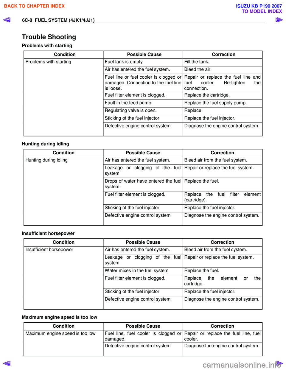
Trouble Shooting
Problems with starting
Condition Possible Cause Correction
Problems with starting Fuel tank is empty Fill the tank.
Air has entered the fuel system. Bleed the air.
Fuel line or fuel cooler is clogged or
damaged. Connection to the fuel line
is loose. Repair or replace the fuel line and
fuel cooler. Re-tighten the
connection.
Fuel filter element is clogged. Replace the cartridge.
Fault in the feed pump Replace the fuel supply pump.
Regulating valve is open. Replace
Sticking of the fuel injector Replace the fuel injector.
Defective engine control system Diagnose the engine control system.
Hunting during idling
Condition Possible Cause Correction
Hunting during idling Air has entered the fuel system. Bleed air from the fuel system.
Leakage or clogging of the fuel
system Repair or replace the fuel system.
Drops of water have entered the fuel
system. Replace the fuel.
Fuel filter element is clogged. Replace the fuel filter element
(cartridge).
Sticking of the fuel injector Replace the fuel injector.
Defective engine control system Diagnose the engine control system.
Insufficient horsepower
Condition Possible Cause Correction
Insufficient horsepower Air has entered the fuel system. Bleed air from the fuel system.
Leakage or clogging of the fuel
system Repair or replace the fuel system.
W ater mixes in the fuel system Replace the fuel.
Fuel filter element is clogged. Replace the element or the
cartridge.
Sticking of the fuel injector Replace the fuel injector.
Defective engine control system Diagnose the engine control system.
Maximum engine speed is too low
Condition Possible Cause Correction
Maximum engine speed is too low Fuel line, fuel cooler is clogged or
damaged. Repair or replace the fuel line, fuel
cooler.
Defective engine control system Diagnose the engine control system.
BACK TO CHAPTER INDEX
TO MODEL INDEX
ISUZU KB P190 2007
Page 1550 of 6020
FUEL SYSTEM (4JK1/4JJ1) 6C-9
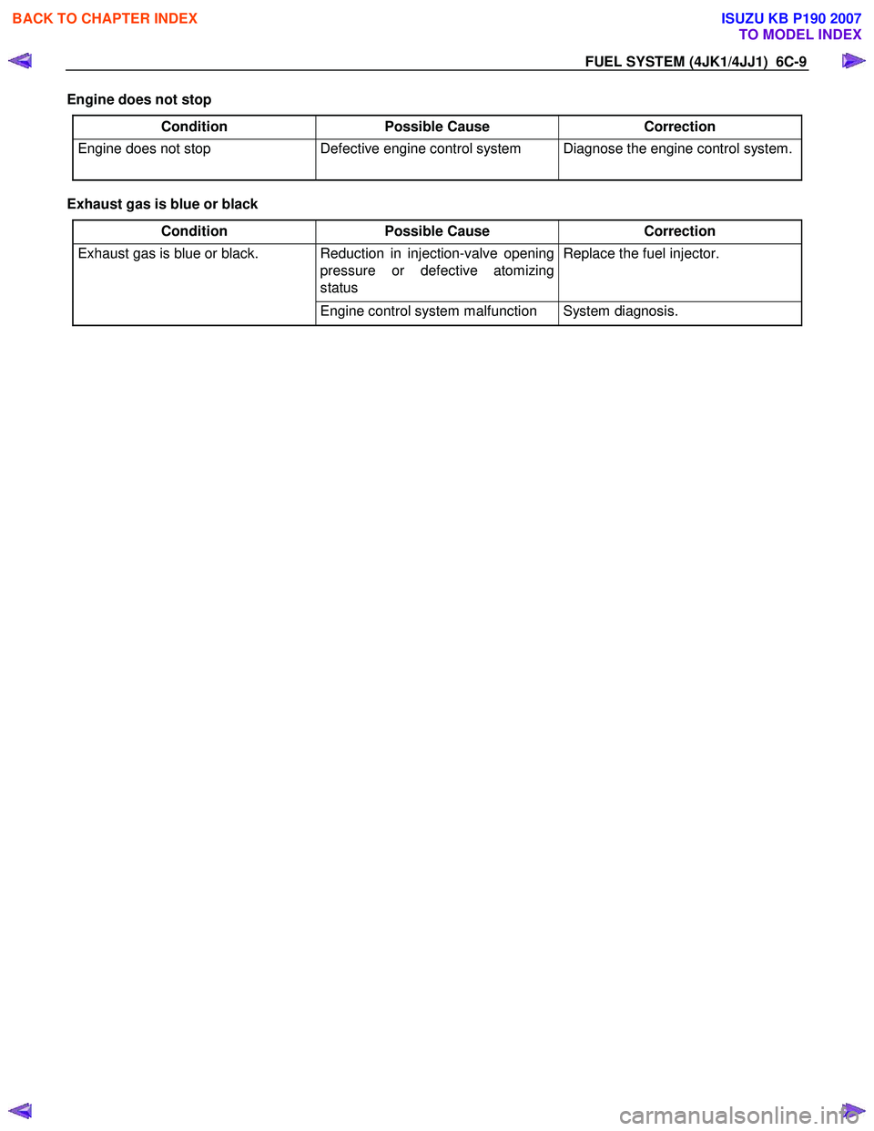
Engine does not stop
Condition Possible Cause Correction
Engine does not stop Defective engine control system Diagnose the engine control system.
Exhaust gas is blue or black
Condition Possible Cause Correction
Exhaust gas is blue or black. Reduction in injection-valve opening
pressure or defective atomizing
status Replace the fuel injector.
Engine control system malfunction System diagnosis.
BACK TO CHAPTER INDEX
TO MODEL INDEX
ISUZU KB P190 2007
Page 1551 of 6020
6C-10 FUEL SYSTEM (4JK1/4JJ1)
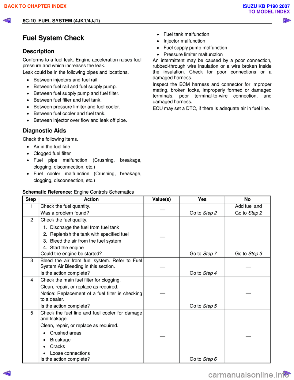
Fuel System Check
Description
Conforms to a fuel leak. Engine acceleration raises fuel
pressure and which increases the leak.
Leak could be in the following pipes and locations.
• Between injectors and fuel rail.
• Between fuel rail and fuel supply pump.
• Between fuel supply pump and fuel filter.
• Between fuel filter and fuel tank.
• Between pressure limiter and fuel cooler.
• Between fuel cooler and fuel tank.
• Between injector over flow and leak off pipe.
Diagnostic Aids
Check the following items.
• Air in the fuel line
• Clogged fuel filter
• Fuel pipe malfunction (Crushing, breakage,
clogging, disconnection, etc.)
• Fuel cooler malfunction (Crushing, breakage,
clogging, disconnection, etc.)
• Fuel tank malfunction
• Injector malfunction
• Fuel supply pump malfunction
• Pressure limiter malfunction
An intermittent may be caused by a poor connection,
rubbed-through wire insulation or a wire broken inside
the insulation. Check for poor connections or a
damaged harness.
Inspect the ECM harness and connector for imprope
r
mating, broken locks, improperly formed or damaged
terminals, poor terminal-to-wire connection, and
damaged harness.
ECU may set a DTC, if there is adequate air in fuel line.
Schematic Reference: Engine Controls Schematics
Step Action Value(s) Yes No
1 Check the fuel quantity. W as a problem found?
Go to Step 2 Add fuel and
Go to Step 2
2 Check the fuel quality.
1. Discharge the fuel from fuel tank
2. Replenish the tank with specified fuel
3. Bleed the air from the fuel system
4. Start the engine
Could the engine be started?
Go to Step 7 Go to Step 3
3 Bleed the air from fuel system. Refer to Fuel
System Air Bleeding in this section.
Is the action complete?
Go to Step 4
4 Check the main fuel filter for clogging.
Clean, repair, or replace as required.
Notice: Replacement of a fuel filter is checking
to a dealer.
Is the action complete?
Go to Step 5
5 Check the fuel line and fuel cooler for damage
and leakage.
Clean, repair, or replace as required.
• Crushed areas
• Breakage
• Cracks
• Loose connections
Is the action complete?
Go to Step 6
BACK TO CHAPTER INDEX
TO MODEL INDEX
ISUZU KB P190 2007
Page 1556 of 6020
FUEL SYSTEM (4JK1/4JJ1) 6C-15
The fuel system consists of many tiny holes and spaces
that allow the movement of fuel from one place to
another. These holes and spaces are milled to
extremely high precision. This is especially true of the
fuel injector.
The fuel injector is very sensitive to foreign material.
Foreign material will result in fuel system breakdown.
Exercise great care not to allow the entry of foreign
material into the fuel system or fuel injector during the
removal and installation procedure.
Note: To avoid electric shock;
Set the switch to the 'OFF' position and disconnect the
negative battery cable before checking or repairing the
fuel injector, wiring or/and connectors.
Removal
1. Remove the cylinder head cover.
Refer to the removal procedure for the cylinde
r
head cover in this manual.
Remove the attachment bolt of the engine oil gauge
guide tube.
2. Loosen the fuel injector clamp fixing bolts and
remove the fuel injector.
If the fuel injector is difficult to remove, use the remover. Use a screwdriver to force the fuel
injector clamp off the fuel injector.
Note: Do not remove the fuel injector sleeve.
Note: Cover the areas exposed during parts removal to
prevent the entry of foreign material into the fuel
system.
3. Mark each fuel injector with the number of the cylinder from which it was removed. Store the fuel
injector in a safe place. Position the fuel injector so
that the nozzle is protected.
Note: Do not tamper with the electromagnetic portion of
the fuel injector. Reduced electromagnetic function will
result in injector failure.
Note: After replacement of the fuel injector, perform the
following procedure.
• All fuel injectors are replaced:
Remove the fuel injector ID code label on the cylinder head cover.
• Any fuel injector(s) is replaced:
Black out the replaced cylinder of the fuel injecto
r
ID code on the fuel injector ID code label with a
marking pen or equivalent.
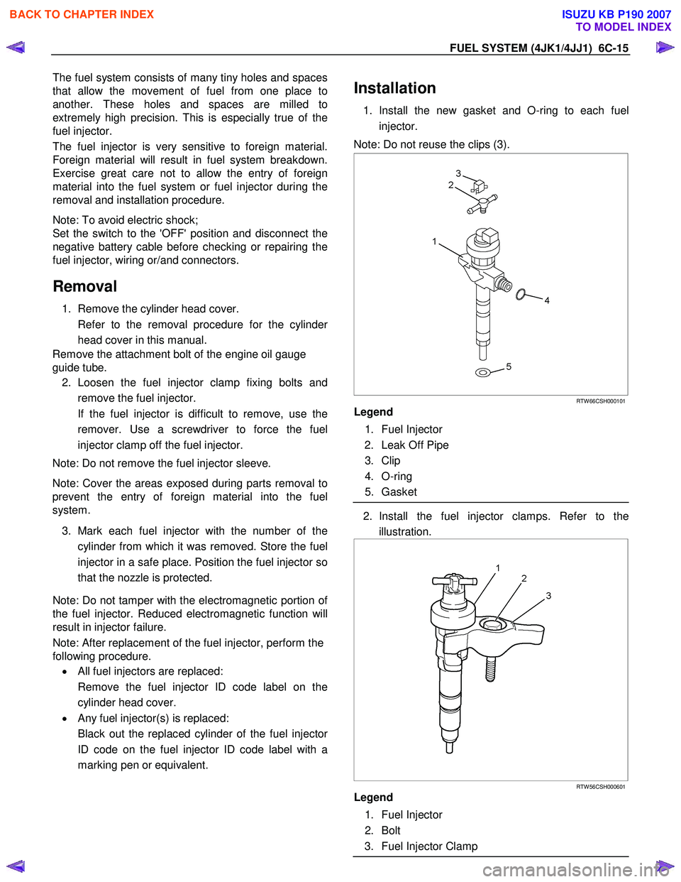
Installation
1. Install the new gasket and O-ring to each fuel
injector.
Note: Do not reuse the clips (3).
RTW 66CSH000101
Legend
1. Fuel Injector
2. Leak Off Pipe
3. Clip
4. O-ring
5. Gasket
2. Install the fuel injector clamps. Refer to the
illustration.
RTW 56CSH000601
Legend
1. Fuel Injector
2. Bolt
3. Fuel Injector Clamp
BACK TO CHAPTER INDEX
TO MODEL INDEX
ISUZU KB P190 2007
Page 1557 of 6020
6C-16 FUEL SYSTEM (4JK1/4JJ1)
3. Apply Engine oil to the threads and seating
surfaces of the clamp bolts.
4. Install the fuel injector clamps to the cylinder head.
5. Temporarily tighten the clamp bolts.
6.
Apply a thin coat of engine oil to the outer surface
of the fuel injector side sleeve nuts.
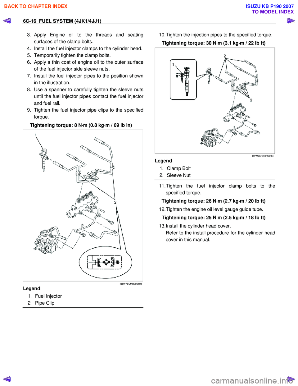
7. Install the fuel injector pipes to the position shown in the illustration.
8. Use a spanner to carefully tighten the sleeve nuts until the fuel injector pipes contact the fuel injecto
r
and fuel rail.
9. Tighten the fuel injector pipe clips to the specified torque.
Tightening torque: 8 N ⋅
⋅⋅
⋅
m (0.8 kg ⋅
⋅⋅
⋅
m / 69 lb in)
RTW 76CMH000101
Legend
1. Fuel Injector
2. Pipe Clip
10. Tighten the injection pipes to the specified torque.
Tightening torque: 30 N ⋅
⋅⋅
⋅
m (3.1 kg ⋅
⋅⋅
⋅
m / 22 lb ft)
RTW 76CSH000201
Legend
1. Clamp Bolt
2. Sleeve Nut
11. Tighten the fuel injector clamp bolts to the
specified torque.
Tightening torque: 26 N ⋅
⋅⋅
⋅
m (2.7 kg ⋅
⋅⋅
⋅
m / 20 lb ft)
12. Tighten the engine oil level gauge guide tube. Tightening torque: 25 N ⋅
⋅⋅
⋅
m (2.5 kg ⋅
⋅⋅
⋅
m / 18 lb ft)
13. Install the cylinder head cover.
Refer to the install procedure for the cylinder head cover in this manual.
BACK TO CHAPTER INDEX
TO MODEL INDEX
ISUZU KB P190 2007