2007 ISUZU KB P190 engine
[x] Cancel search: enginePage 1558 of 6020
FUEL SYSTEM (4JK1/4JJ1) 6C-17
Record the Fuel Injector ID Code Data from
each injector housing
1. Remove each fuel injector harness connector.
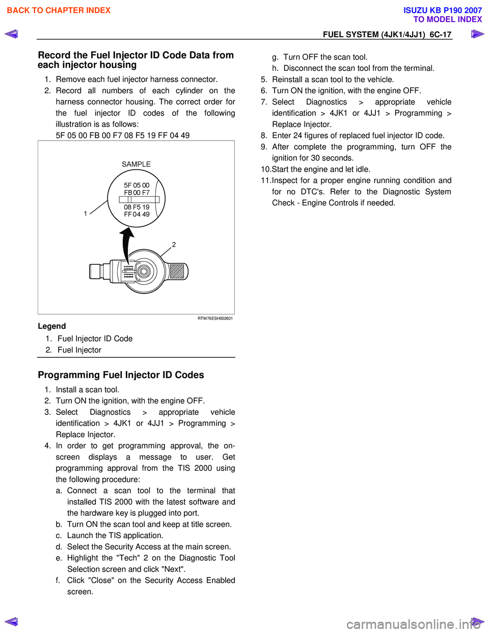
2. Record all numbers of each cylinder on the harness connector housing. The correct order fo
r
the fuel injector ID codes of the following
illustration is as follows:
5F 05 00 FB 00 F7 08 F5 19 FF 04 49
RTW 76ESH002601
Legend
1. Fuel Injector ID Code
2. Fuel Injector
Programming Fuel Injector ID Codes
1. Install a scan tool.
2. Turn ON the ignition, with the engine OFF.
3. Select Diagnostics > appropriate vehicle identification > 4JK1 or 4JJ1 > Programming >
Replace Injector.
4. In order to get programming approval, the on- screen displays a message to user. Get
programming approval from the TIS 2000 using
the following procedure:
a. Connect a scan tool to the terminal that installed TIS 2000 with the latest software and
the hardware key is plugged into port.
b. Turn ON the scan tool and keep at title screen.
c. Launch the TIS application.
d. Select the Security Access at the main screen.
e. Highlight the "Tech" 2 on the Diagnostic Tool Selection screen and click "Next".
f. Click "Close" on the Security Access Enabled screen.
g. Turn OFF the scan tool.
h. Disconnect the scan tool from the terminal.
5. Reinstall a scan tool to the vehicle.
6. Turn ON the ignition, with the engine OFF.
7. Select Diagnostics > appropriate vehicle identification > 4JK1 or 4JJ1 > Programming >
Replace Injector.
8. Enter 24 figures of replaced fuel injector ID code.
9.
After complete the programming, turn OFF the
ignition for 30 seconds.
10.Start the engine and let idle.
11.Inspect for a proper engine running condition and for no DTC's. Refer to the Diagnostic System
Check - Engine Controls if needed.
BACK TO CHAPTER INDEX
TO MODEL INDEX
ISUZU KB P190 2007
Page 1563 of 6020

6C-22 FUEL SYSTEM (4JK1/4JJ1)
Removal
1. Remove the starter motor.
• Refer to the removal procedure for engine
electricals in this manual.
2. Remove the fuel feed pipe (1) for supply pump.
Note: Cover the areas exposed during parts removal to
prevent the entry of foreign material into the fuel
system.
RTW 76CSH000501
3. Remove the fuel hose (1).
Note: Cover the areas exposed during parts removal to
prevent the entry of foreign material into the fuel
system.
RTW 76CSH000601
4. Remove the leak off pipe and hose (1).
Note: Cover the areas exposed during parts removal to
prevent the entry of foreign material into the fuel
system.
RTW 76CSH000301
5. Disconnect the fuel rail pressure sensor harness
connector (1).
LNW 76CSH001601
BACK TO CHAPTER INDEX
TO MODEL INDEX
ISUZU KB P190 2007
Page 1566 of 6020
FUEL SYSTEM (4JK1/4JJ1) 6C-25
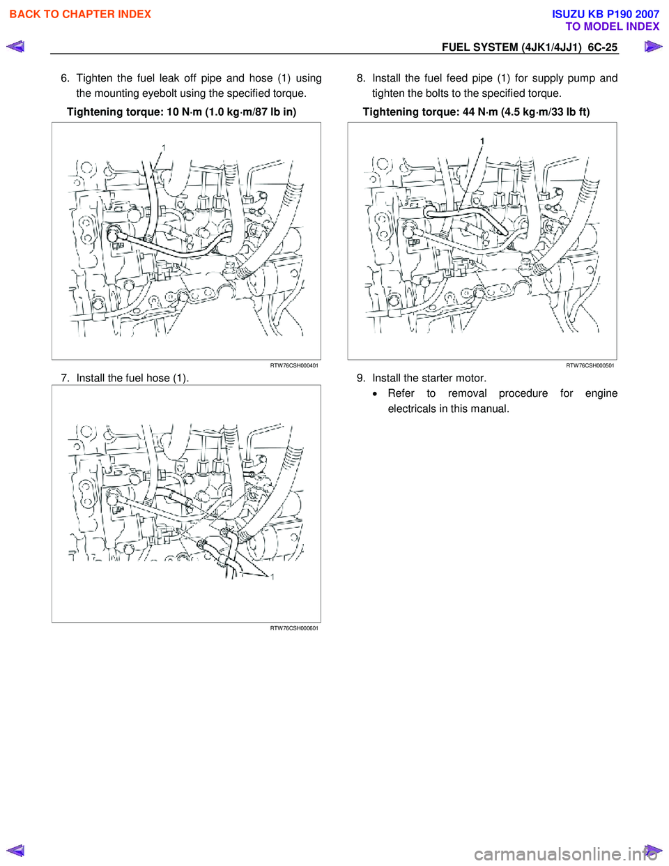
6. Tighten the fuel leak off pipe and hose (1) using
the mounting eyebolt using the specified torque.
Tightening torque: 10 N ⋅
⋅⋅
⋅
m (1.0 kg ⋅
⋅⋅
⋅
m/87 lb in)
RTW 76CSH000401
7. Install the fuel hose (1).
RTW 76CSH000601
8. Install the fuel feed pipe (1) for supply pump and
tighten the bolts to the specified torque.
Tightening torque: 44 N ⋅
⋅⋅
⋅
m (4.5 kg ⋅
⋅⋅
⋅
m/33 lb ft)
RTW 76CSH000501
9. Install the starter motor. • Refer to removal procedure for engine
electricals in this manual.
BACK TO CHAPTER INDEX
TO MODEL INDEX
ISUZU KB P190 2007
Page 1569 of 6020
6C-28 FUEL SYSTEM (4JK1/4JJ1)
Removal
1. Partially drain the engine coolant.
Refer to drain procedure for engine cooling in this manual.
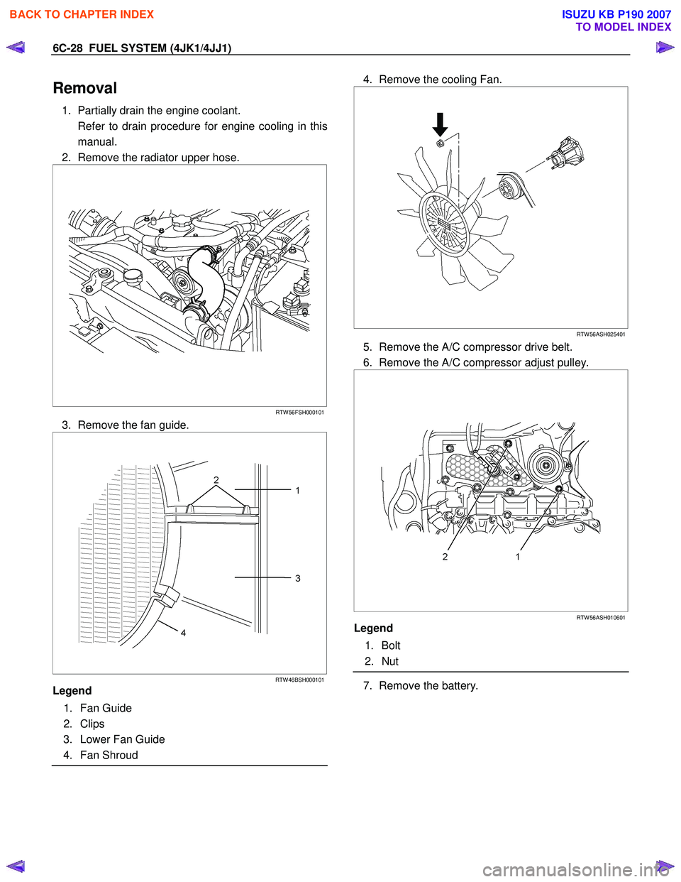
2. Remove the radiator upper hose.
RTW 56FSH000101
3. Remove the fan guide.
RTW 46BSH000101
Legend
1. Fan Guide
2. Clips
3. Lower Fan Guide
4. Fan Shroud
4. Remove the cooling Fan.
RTW 56ASH025401
5. Remove the A/C compressor drive belt.
6. Remove the A/C compressor adjust pulley.
RTW 56ASH010601
Legend
1. Bolt
2. Nut
7. Remove the battery.
BACK TO CHAPTER INDEX
TO MODEL INDEX
ISUZU KB P190 2007
Page 1570 of 6020
FUEL SYSTEM (4JK1/4JJ1) 6C-29
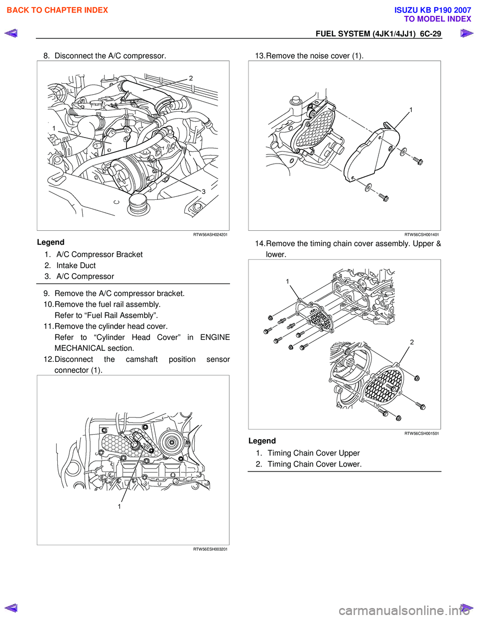
8. Disconnect the A/C compressor.
RTW 56ASH024201
Legend
1. A/C Compressor Bracket
2. Intake Duct
3. A/C Compressor
9. Remove the A/C compressor bracket.
10. Remove the fuel rail assembly.
Refer to “Fuel Rail Assembly”.
11. Remove the cylinder head cover.
Refer to “Cylinder Head Cover” in ENGINE MECHANICAL section.
12. Disconnect the camshaft position senso
r
connector (1).
RTW 56ESH003201
13. Remove the noise cover (1).
RTW 56CSH001401
14. Remove the timing chain cover assembly. Upper &
lower.
RTW 56CSH001501
Legend
1. Timing Chain Cover Upper
2. Timing Chain Cover Lower.
BACK TO CHAPTER INDEX
TO MODEL INDEX
ISUZU KB P190 2007
Page 1577 of 6020
6C-36 FUEL SYSTEM (4JK1/4JJ1)
15. Install the cylinder head cover.
Refer to "Cylinder Head Cover" in ENGINE MECHANICAL section.
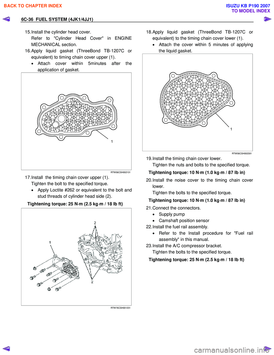
16. Apply liquid gasket (ThreeBond TB-1207C o
r
equivalent) to timing chain cover upper (1).
•
Attach cover within 5minutes after the
application of gasket.
RTW 56CSH002101
17. Install the timing chain cover upper (1).
Tighten the bolt to the specified torque. •
Apply Loctite #262 or equivalent to the bolt and
stud threads of cylinder head side (2).
Tightening torque: 25 N ⋅
⋅⋅
⋅
m (2.5 kg ⋅
⋅⋅
⋅
m / 18 lb ft)
RTW 76CSH001201
18. Apply liquid gasket (ThreeBond TB-1207C o
r
equivalent) to the timing chain cover lower (1).
•
Attach the cover within 5 minutes of applying
the liquid gasket.
RTW 56CSH002301
19. Install the timing chain cover lower.
Tighten the nuts and bolts to the specified torque.
Tightening torque: 10 N ⋅
⋅⋅
⋅
m (1.0 kg ⋅
⋅⋅
⋅
m / 87 lb in)
20. Install the noise cover to the timing chain cove
r
lower.
Tighten the bolts to the specified torque.
Tightening torque: 10 N ⋅
⋅⋅
⋅
m (1.0 kg ⋅
⋅⋅
⋅
m / 87 lb in)
21. Connect the connectors. • Supply pump
• Camshaft position sensor
22. Install the fuel rail assembly. • Refer to the Install procedure for "Fuel rail
assembly" in this manual.
23. Install the A/C compressor bracket.
Tighten the bolts to the specified torque.
Tightening torque: 25 N ⋅
⋅⋅
⋅
m (2.5 kg ⋅
⋅⋅
⋅
m / 18 lb ft)
BACK TO CHAPTER INDEX
TO MODEL INDEX
ISUZU KB P190 2007
Page 1578 of 6020

FUEL SYSTEM (4JK1/4JJ1) 6C-37
24. Install the A/C compressor.
RTW 56ASH004201
Legend
1. A/C Compressor Bracket
2. Intake Duct
3. A/C Compressor
Tighten the bolts to the specified torque.
Tightening torque: 44 N ⋅
⋅⋅
⋅
m (4.5 kg ⋅
⋅⋅
⋅
m / 33 lb ft)
25. Install the battery.
26. Install the A/C compressor adjust pulley.
RTW 56ASH010601
Legend
1. Bolt
2. Nut
Tighten the nut and bolt to the specified torque.
Bolt Tightening torque: 25 N ⋅
⋅⋅
⋅
m (2.5 kg ⋅
⋅⋅
⋅
m/18 lb ft)
Nut Tightening torque: 25 N ⋅
⋅⋅
⋅
m (2.5 kg ⋅
⋅⋅
⋅
m/18 lb ft)
27. Install the A/C compressor drive belt.
Refer to the drive belt tension check procedure fo
r
Heating and air conditioning in this manual.
28. Install the cooling fan.
29. Install the fan guide.
30. Install the radiator upper hose.
31. Replenish the engine coolant.
Fuel Supply Pump Relearn Procedure
The ECM goes through a fuel supply pump learn
procedure to fine tune the current supplied to the fuel
rail pressure (FRP) regulator. This learning process in
only performed when the engine is idling.
1. Install the scan tool.
2. Turn ON the ignition, with the engine OFF.
3. Command the Supply Pump Learn Reset with the scan tool.
4. Observe the Supply Pump Status parameter with the scan tool. Confirm the scan tool indicates Not
Learn.
5. Start the engine and let idle until engine coolant temperature (ECT) reads 149°F (65°C) or highe
r
while observing Supply Pump Status parameter
with the scant tool. The scan tool changes status
Not Learn > Learning > Learned.
6. If the ECM has correctly learned the fuel supply pump current adjustment, the Supply Pump Status
parameter on the scan tool will repeatedly indicate
Learning and Learned.
BACK TO CHAPTER INDEX
TO MODEL INDEX
ISUZU KB P190 2007
Page 1582 of 6020
FUEL SYSTEM (4JK1/4JJ1) 6C-41
Removal
Note: W hen repairs to the fuel system have been
completed, start the engine and check the fuel system
for loose connections or leakage. For the fuel system
diagnosis, see Section "Drivability and Emission".
1. Disconnect the battery ground cable.
2. Slowly loosen the fuel filler cap.
Note: Be careful that fuel does not spout out because o
f
change of pressure in the fuel tank.
Note: Cover opening of the filler neck to prevent an
y
dust entering. 3. Jack up the vehicle.
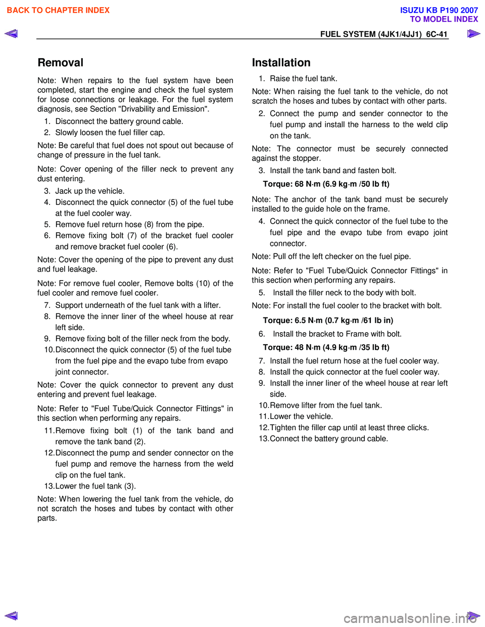
4. Disconnect the quick connector (5) of the fuel tube at the fuel cooler way.
5. Remove fuel return hose (8) from the pipe.
6. Remove fixing bolt (7) of the bracket fuel coole
r
and remove bracket fuel cooler (6).
Note: Cover the opening of the pipe to prevent any dust
and fuel leakage.
Note: For remove fuel cooler, Remove bolts (10) of the
fuel cooler and remove fuel cooler.
7. Support underneath of the fuel tank with a lifter.
8. Remove the inner liner of the wheel house at rea
r
left side.
9. Remove fixing bolt of the filler neck from the body.
10. Disconnect the quick connector (5) of the fuel tube from the fuel pipe and the evapo tube from evapo
joint connector.
Note: Cover the quick connector to prevent any dust
entering and prevent fuel leakage.
Note: Refer to "Fuel Tube/Quick Connector Fittings" in
this section when performing any repairs.
11. Remove fixing bolt (1) of the tank band and remove the tank band (2).
12. Disconnect the pump and sender connector on the fuel pump and remove the harness from the weld
clip on the fuel tank.
13. Lower the fuel tank (3).
Note: W hen lowering the fuel tank from the vehicle, do
not scratch the hoses and tubes by contact with othe
r
parts.
Installation
1. Raise the fuel tank.
Note: W hen raising the fuel tank to the vehicle, do not
scratch the hoses and tubes by contact with other parts.
2. Connect the pump and sender connector to the fuel pump and install the harness to the weld clip
on the tank.
Note: The connector must be securely connected
against the stopper.
3. Install the tank band and fasten bolt.
Torque: 68 N ⋅
⋅⋅
⋅
m (6.9 kg ⋅
⋅⋅
⋅
m /50 lb ft)
Note: The anchor of the tank band must be securely
installed to the guide hole on the frame.
4. Connect the quick connector of the fuel tube to the fuel pipe and the evapo tube from evapo joint
connector.
Note: Pull off the left checker on the fuel pipe.
Note: Refer to "Fuel Tube/Quick Connector Fittings" in
this section when performing any repairs.
5. Install the filler neck to the body with bolt.
Note: For install the fuel cooler to the bracket with bolt.
Torque: 6.5 N ⋅
⋅⋅
⋅
m (0.7 kg ⋅
⋅⋅
⋅
m /61 lb in)
6. Install the bracket to Frame with bolt. Torque: 48 N ⋅
⋅⋅
⋅
m (4.9 kg ⋅
⋅⋅
⋅
m /35 lb ft)
7. Install the fuel return hose at the fuel cooler way.
8. Install the quick connector at the fuel cooler way.
9. Install the inner liner of the wheel house at rear left side.
10. Remove lifter from the fuel tank.
11. Lower the vehicle.
12. Tighten the filler cap until at least three clicks.
13. Connect the battery ground cable.
BACK TO CHAPTER INDEX
TO MODEL INDEX
ISUZU KB P190 2007