2007 ISUZU KB P190 engine oil
[x] Cancel search: engine oilPage 3960 of 6020
Automatic Transmission – 4L60E – On-vehicle Servicing Page 7C4–47
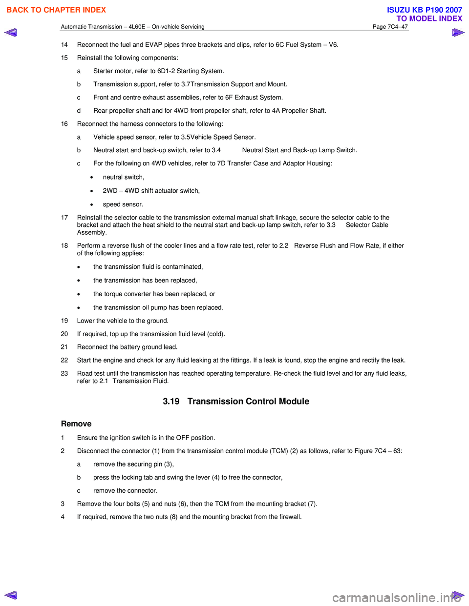
14 Reconnect the fuel and EVAP pipes three brackets and clips, refer to 6C Fuel System – V6.
15 Reinstall the following components:
a Starter motor, refer to 6D1-2 Starting System.
b Transmission support, refer to 3.7 Transmission Support and Mount.
c Front and centre exhaust assemblies, refer to 6F Exhaust System.
d Rear propeller shaft and for 4WD front propeller shaft, refer to 4A Propeller Shaft.
16 Reconnect the harness connectors to the following: a Vehicle speed sensor, refer to 3.5 Vehicle Speed Sensor.
b Neutral start and back-up switch, refer to 3.4 Neutral Start and Back-up Lamp Switch.
c For the following on 4W D vehicles, refer to 7D Transfer Case and Adaptor Housing:
• neutral switch,
• 2WD – 4WD shift actuator switch,
• speed sensor.
17 Reinstall the selector cable to the transmission external manual shaft linkage, secure the selector cable to the bracket and attach the heat shield to the neutral start and back-up lamp switch, refer to 3.3 Selector Cable
Assembly.
18 Perform a reverse flush of the cooler lines and a flow rate test, refer to 2.2 Reverse Flush and Flow Rate, if either of the following applies:
• the transmission fluid is contaminated,
• the transmission has been replaced,
• the torque converter has been replaced, or
• the transmission oil pump has been replaced.
19 Lower the vehicle to the ground.
20 If required, top up the transmission fluid level (cold).
21 Reconnect the battery ground lead.
22 Start the engine and check for any fluid leaking at the fittings. If a leak is found, stop the engine and rectify the leak.
23 Road test until the transmission has reached operating temperature. Re-check the fluid level and for any fluid leaks, refer to 2.1 Transmission Fluid.
3.19 Transmission Control Module
Remove
1 Ensure the ignition switch is in the OFF position.
2 Disconnect the connector (1) from the transmission control module (TCM) (2) as follows, refer to Figure 7C4 – 63: a remove the securing pin (3),
b press the locking tab and swing the lever (4) to free the connector,
c remove the connector.
3 Remove the four bolts (5) and nuts (6), then the TCM from the mounting bracket (7).
4 If required, remove the two nuts (8) and the mounting bracket from the firewall.
BACK TO CHAPTER INDEX
TO MODEL INDEX
ISUZU KB P190 2007
Page 3975 of 6020
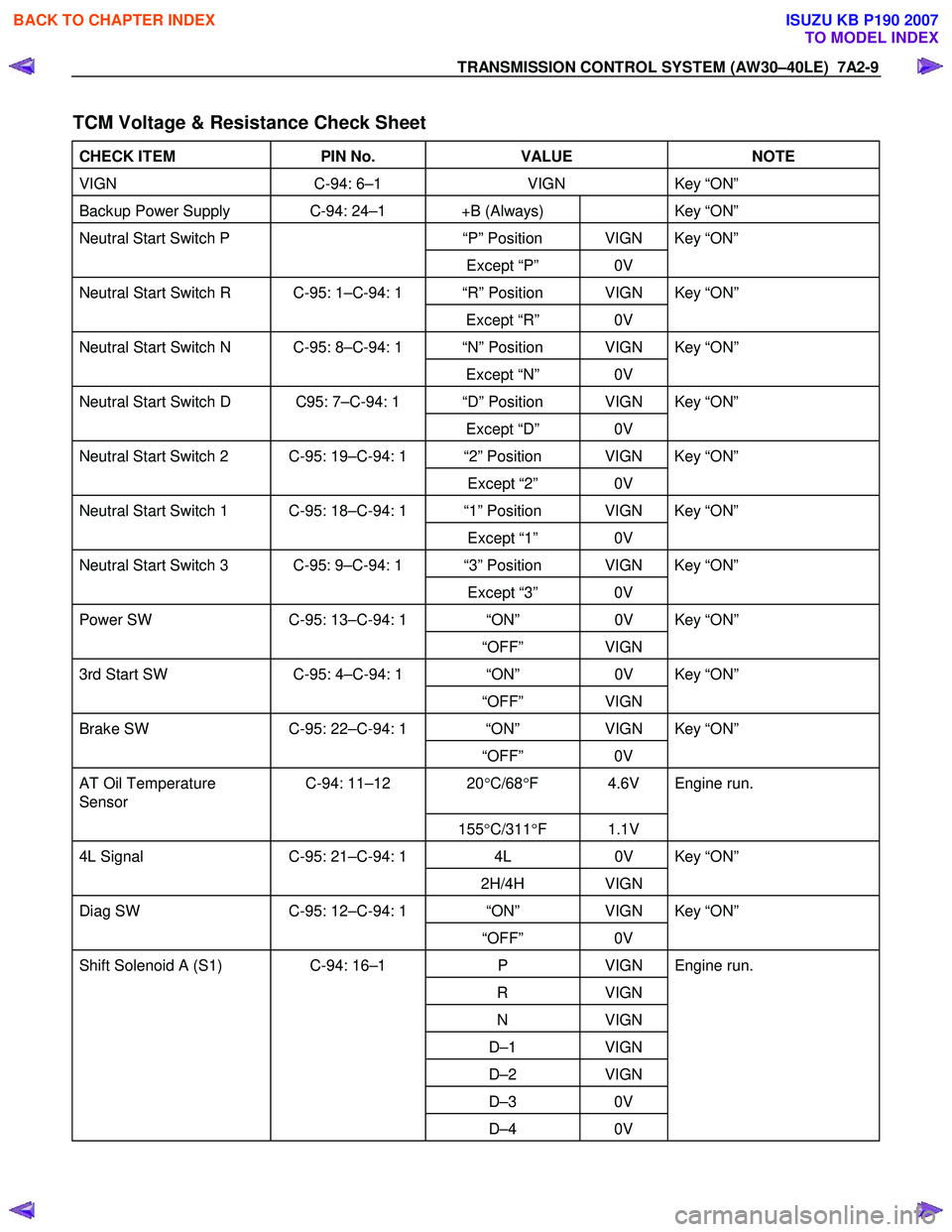
TRANSMISSION CONTROL SYSTEM (AW30–40LE) 7A2-9
TCM Voltage & Resistance Check Sheet
CHECK ITEM PIN No. VALUE NOTE
VIGN C-94: 6–1 VIGN Key “ON”
Backup Power Supply C-94: 24–1 +B (Always) Key “ON”
Neutral Start Switch P “P” Position VIGN Key “ON”
Except “P” 0V
Neutral Start Switch R C-95: 1–C-94: 1 “R” Position VIGN Key “ON”
Except “R” 0V
Neutral Start Switch N C-95: 8–C-94: 1 “N” Position VIGN Key “ON”
Except “N” 0V
Neutral Start Switch D C95: 7–C-94: 1 “D” Position VIGN Key “ON”
Except “D” 0V
Neutral Start Switch 2 C-95: 19–C-94: 1 “2” Position VIGN Key “ON”
Except “2” 0V
Neutral Start Switch 1 C-95: 18–C-94: 1 “1” Position VIGN Key “ON”
Except “1” 0V
Neutral Start Switch 3 C-95: 9–C-94: 1 “3” Position VIGN Key “ON”
Except “3” 0V
Power SW C-95: 13–C-94: 1 “ON” 0V Key “ON”
“OFF” VIGN
3rd Start SW C-95: 4–C-94: 1 “ON” 0V Key “ON”
“OFF” VIGN
Brake SW C-95: 22–C-94: 1 “ON” VIGN Key “ON”
“OFF” 0V
AT Oil Temperature
Sensor C-94: 11–12 20
°C/68 °F 4.6V Engine run.
155°C/311 °F 1.1V
4L Signal C-95: 21–C-94: 1 4L 0V Key “ON”
2H/4H VIGN
Diag SW C-95: 12–C-94: 1 “ON” VIGN Key “ON”
“OFF” 0V
Shift Solenoid A (S1) C-94: 16–1 P VIGN Engine run.
R VIGN
N VIGN
D–1 VIGN
D–2 VIGN
D–3 0V
D–4 0V
BACK TO CHAPTER INDEX
TO MODEL INDEX
ISUZU KB P190 2007
Page 3976 of 6020
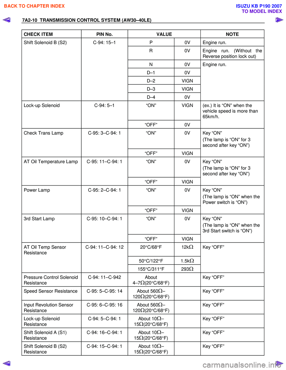
7A2-10 TRANSMISSION CONTROL SYSTEM (AW30–40LE)
CHECK ITEM PIN No. VALUE NOTE
Shift Solenoid B (S2) C-94: 15–1 P 0V Engine run.
R 0V Engine run. (W ithout the
Reverse position lock out)
N 0V Engine run.
D–1 0V
D–2 VIGN
D–3 VIGN
D–4 0V
Lock-up Solenoid C-94: 5–1 “ON” VIGN (ex.) It is “ON” when the
vehicle speed is more than
65km/h.
“OFF” 0V
Check Trans Lamp C-95: 3–C-94: 1 “ON” 0V Key “ON”
(The lamp is “ON” for 3
second after key “ON”)
“OFF” VIGN
AT Oil Temperature Lamp C-95: 11–C-94: 1 “ON” 0V Key “ON”
(The lamp is “ON” for 3
second after key “ON”)
“OFF” VIGN
Power Lamp C-95: 2–C-94: 1 “ON” 0V Key “ON”
(The lamp is “ON” when the
Power switch is “ON”)
“OFF” VIGN
3rd Start Lamp C-95: 10–C-94: 1 “ON” 0V Key “ON”
(The lamp is “ON” when the
3rd Start switch is “ON”)
“OFF” VIGN
AT Oil Temp Sensor
Resistance C-94: 11–C-94: 12 20
°C/68 °F 12kΩ Key “OFF”
50°C/122 °F 1.5kΩ
155°C/311 °F 293Ω
Pressure Control Solenoid
Resistance C-94: 11–C-942 About
4–7
Ω(20 °C/68 °F)
Key “OFF”
Speed Sensor Resistance C-95: 5–C-95: 14 About 560Ω–
120
Ω(20 °C/68 °F)
Key “OFF”
Input Revolution Sensor
Resistance C-95: 6–C-95: 16 About 560Ω–
120
Ω(20 °C/68 °F)
Key “OFF”
Lock-up Solenoid
Resistance C-94: 5–C-94: 1 About 10Ω–
15
Ω(20 °C/68 °F)
Key “OFF”
Shift Solenoid A (S1)
Resistance C-94: 16–C-94: 1 About 10Ω–
15
Ω(20 °C/68 °F)
Key “OFF”
Shift Solenoid B (S2)
Resistance C-94: 15–C-94: 1 About 10Ω–
15
Ω(20 °C/68 °F)
Key “OFF”
BACK TO CHAPTER INDEX
TO MODEL INDEX
ISUZU KB P190 2007
Page 3979 of 6020
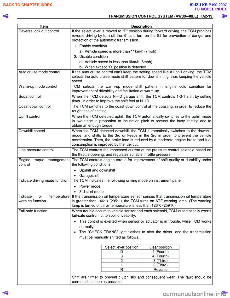
TRANSMISSION CONTROL SYSTEM (AW30–40LE) 7A2-13
Item Description
Reverse lock out control If the select lever is moved to "R" position during forward driving, the TCM prohibits
reverse driving by turn off the S1 and turn on the S2 for prevention of danger and
protection of the automatic transmission.
1. Enable condition a) Vehicle speed is more than 11km/h (7mph).
2. Disable condition a) Vehicle speed is less than 9km/h (6mph).
b) W hen except "R" position is detected.
Auto cruise mode control If the auto cruise control can’t keep the setting speed like a uphill driving, the TCM selects the auto cruise mode shift pattern for downshifting, thus keeping the vehicle
speed.
W arm-up mode control TCM selects the warm-up mode shift pattern in engine cold condition for improvement of drivability and facilitation of warm-up.
Squat control W hen the TCM detects N→D garage shift, the TCM controls 1-3-1 shift by setting
timer, in order to improve the shift feel at N →D.
Coast down control The TCM switches to the coast down control at the coasting, in order to reduce the
roughness of shifting.
Uphill control W hen the TCM detected uphill, the TCM automatically switches to the uphill mode
in two-stage in proportion to inclination pitch to prevent the busy shifting and to
obtain an enough torque.
Downhill control W hen the TCM detected downhill, the TCM automatically switches to the downhill
mode, and shifts to the 3rd or keeps in the 3rd in order to prevent the vehicle
acceleration. Then, the brake load is reduced by a moderate engine brake and fuel
consumption is improved by the fuel cut.
Line pressure control The TCM controls the impressed current of the pressure control solenoid based on the throttle opening, and regulates suitable throttle pressure.
Engine truque management
control The TCM controls engine torque for improvement of shift quality or durability under
the following conditions.
• Upshift and downshift
• Garageshift
Indicate driving mode function The TCM indicates the following driving mode on instrument panel.
• Power mode
• 3rd start mode
Indicate oil temperature
warning function If the transmission oil temperature sensor senses that transmission oil temperature
is greater than 146 °C (295 °F) , the TCM turns on ATF warning lamp. (The warning
lamp is turned off, if oil temperature is less than 126 °C/ 259 °F .)
Fail-safe function W hen trouble occurs to vehicle sensor and each solenoid, TCM automatically exerts
fail-safe control not to spoil driveability.
• This control is exerted when sensor or actuator is in trouble, while TCM works
normally.
• The "CHECK TRANS" light flashes to alert the driver, and the transmission
must be manually shifted as follows.
Select lever position Gear position
D 4 (Fourth)
3 4 (Fourth)
2 3 (Third)
L 3 (Third)
R Reverse
Shift are firmer to prevent clutch slip and consequent wear. The fault should be
corrected as soon as possible.
BACK TO CHAPTER INDEX
TO MODEL INDEX
ISUZU KB P190 2007
Page 3989 of 6020
TRANSMISSION CONTROL SYSTEM (AW30–40LE) 7A2-23
Diagnostic Trouble Codes
The purpose of the “Diagnostic Trouble Codes” mode is
to display stored TCM trouble codes.
W hen “Diagnostic Trouble Codes” is selected an
“Application Menu” screen appears.
Read DTC Information
W hen “Read DTC Information” is selected, an
“Application Menu” appears with a list of DTC
information function keys addressing DTC specifics and
their origins.
Function key selections may vary for particular vehicle
and/or system.
Requested emission-related DTCs
Clear DTC Information
The purpose of the “Clear DTC Information” mode is to
command the clearing of stored TCM trouble codes.
W hen “Clear DTC Information” is selected, a “Clea
r
DTC Information”, warning screen appears. This screen
informs you that by cleaning DTC's, “all stored DTC
information in controller will be erased”.
Do you want to clear DTC's (Yes/No).
Press either the Yes or No key when answering.
After clearing codes, confirm system operation by test-
driving the vehicle.
Allow the vehicle to shift through all four forward gears
in a manner which attempts to repeat the failure
condition.
NOTE: W hen the trouble has not been repaired and
the trouble code cannot be erased, check the vehicle
again.
Data Display
The purpose of the “Data Display” mode is to
continuously monitor data parameters.
The current actual values of all important sensors and
signals in the system are displayed through F1 mode.
W hen “Data Display” is selected an “Application Menu”
appears. “Transmission Data Display”.
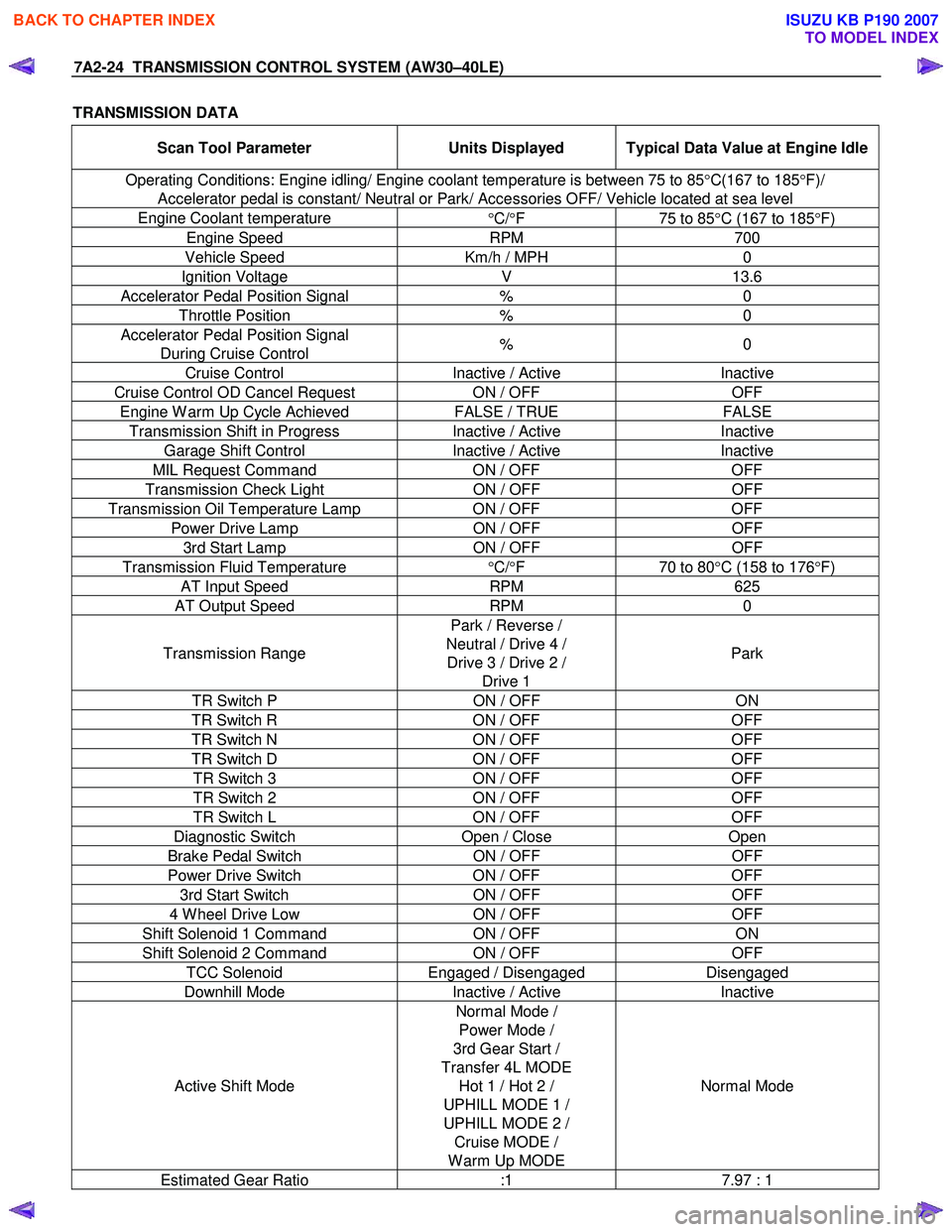
See “Transmission Data” on next page.
Snapshot
W hen “Snapshot” is selected an “Application Menu”
appears.
W hen “Transmission Snapshot” application is selected
from the “Application Menu”, a “Snapshot Menu”
appears, displaying several options. “Snapshot” options
may vary from one system to another.
“Snapshot” allows a recording of all vehicle parameters.
There parameters may then be replayed at a future
point in time.
This action allows you to focus on making the condition
occur, rather than trying to view all of the data in
anticipation of the fault. The snapshot will collect
parameter information around a trigger point that you
select.
W hen a snapshot is taken, it is recorded onto the
PCMCIA memory card. W hen the Tech 2 is powered
down. Snapshots are not lost.
Actuator Test
The purpose of “Actuator Test” mode is to check fo
r
correct operation of electronic system actuators.
Solenoid 2-3 Test, Solenoid 1-2/3-4 and Test TCC
Solenoid Test
You can operate the solenoids by pressing the “ON”
and “OFF” buttons.
Preconditions: P–N position, no vehicle speed, no
engine speed
Pressure Control Solenoid (PCS)
You can set desired PCS Current using the “ON” and
“OFF” button. The PCS Data informs about PCS
Current, Pressure and Duty Cycle.
Preconditions: P–N position, no engine speed, no
vehicle speed
3rd Start Lamp Test, Power Lamp Test, AT Oil
Temperature Lamp Test and Check Light Test
You can operate the lamps by pressing the “ON” and
“OFF” buttons.
Preconditions: none
NOTE: Freeze Frame
Freeze Frame is an element of the Diagnostic
Management System which stores various vehicle
information at the moment an emission-related fault
is stored in memory and when the Check Trans
Lamp is commanded on. These data can help to
identity the cause of a fault. Refer to Storing An
d
Erasing Freeze Frame Data for more detaile
d
information.
BACK TO CHAPTER INDEX
TO MODEL INDEX
ISUZU KB P190 2007
Page 3990 of 6020
7A2-24 TRANSMISSION CONTROL SYSTEM (AW30–40LE)
TRANSMISSION DATA
Scan Tool Parameter Units Displayed Typical Data Value at Engine Idle
Operating Conditions: Engine idling/ Engine coolant temperature is between 75 to 85 °C(167 to 185 °F)/
Accelerator pedal is constant/ Neutral or Park/ Accessories OFF/ Vehicle located at sea level
Engine Coolant temperature °C/ °F 75 to 85°C (167 to 185 °F)
Engine Speed RPM 700
Vehicle Speed Km/h / MPH 0
Ignition Voltage V 13.6
Accelerator Pedal Position Signal % 0
Throttle Position % 0
Accelerator Pedal Position Signal
During Cruise Control % 0
Cruise Control
Inactive / Active Inactive
Cruise Control OD Cancel Request ON / OFF OFF
Engine W arm Up Cycle Achieved FALSE / TRUE FALSE
Transmission Shift in Progress Inactive / Active Inactive
Garage Shift Control Inactive / Active Inactive
MIL Request Command ON / OFF OFF
Transmission Check Light ON / OFF OFF
Transmission Oil Temperature Lamp ON / OFF OFF
Power Drive Lamp ON / OFF OFF
3rd Start Lamp ON / OFF OFF
Transmission Fluid Temperature
°C/ °F 70 to 80°C (158 to 176 °F)
AT Input Speed RPM 625
AT Output Speed RPM 0
Transmission Range Park / Reverse /
Neutral / Drive 4 / Drive 3 / Drive 2 / Drive 1 Park
TR Switch P
ON / OFF ON
TR Switch R ON / OFF OFF
TR Switch N ON / OFF OFF
TR Switch D ON / OFF OFF
TR Switch 3 ON / OFF OFF
TR Switch 2 ON / OFF OFF
TR Switch L ON / OFF OFF
Diagnostic Switch Open / Close Open
Brake Pedal Switch ON / OFF OFF
Power Drive Switch ON / OFF OFF
3rd Start Switch ON / OFF OFF
4 W heel Drive Low ON / OFF OFF
Shift Solenoid 1 Command ON / OFF ON
Shift Solenoid 2 Command ON / OFF OFF
TCC Solenoid Engaged / Disengaged Disengaged
Downhill Mode Inactive / Active Inactive
Active Shift Mode Normal Mode /
Power Mode /
3rd Gear Start /
Transfer 4L MODE Hot 1 / Hot 2 /
UPHILL MODE 1 /
UPHILL MODE 2 / Cruise MODE /
W arm Up MODE Normal Mode
Estimated Gear Ratio
:1 7.97 : 1
BACK TO CHAPTER INDEX
TO MODEL INDEX
ISUZU KB P190 2007
Page 4012 of 6020
7A2-46 TRANSMISSION CONTROL SYSTEM (AW30–40LE)
(2) Not emergency mode.
(3) All of the following conditions are met. • Device Control is not operating.
• Disable Normal Communication service is
receiving enable.
• DTC Clear is not operating.
Condition For Setting The DTC
DTC P0707
All of the following conditions are met for 30 seconds or
more continuously.
• All of the switches are “OFF”.
• Output revolution is more than 30 km/h (19 mph).
• Output revolution sensor is not detecting failure o
r
not deciding failure.
• The engine revolution is more than 1500 rpm.
DTC P0708
The following condition is met at 10 seconds
continuously.
• 2 switches or more are “ON” at the same time.
Action Taken When The DTC Sets
• No 3rd start mode.
• No slope control.
• No coast control.
• No output revolution sensor failure detection.
• No input revolution sensor failure detection.
• Keep oil temperature sensor OPEN failure detection accumulated timer.
• No T/F HI-Low SW failure detection.
• No shift solenoid functional failure detection.
• No L-up solenoid functional failure detection.
• No engine torque reduction at stall.
• Regard as D position. (DTC P0707)
• There is a priority in order of D, 3, 2, L, R, N, and P.
(DTC P0708)
• Check Trans “ON”.
• DTC stored.
• MIL request “ON”. (EURO 4 only)
Conditions For Clearing The DTC
•
The DTC can be cleared from the TCM history by
using a scan tool.
• The DTC will be cleared from history when the vehicle has achieved 40 warm-up cycles without a
failure reported.
•
After more than 1 second has elapsed after the
ignition key has been turned “ON”, short between
No.11 and No.4 (ground) of DLC (Data Link
Connector). Then, after 1 second, but within 6
seconds, discontinue shorting.
Diagnostic Aids
• Inspect the wiring for poor electrical connection at the
TCM. Look for possible bent, backed out, deformed
or damaged terminals. Check for weak terminal
tension as well. Also check for a chafed wire that
could short to bare metal or other wiring.
Inspect for a broken wire inside the insulation.
• W hen diagnosing for a possible intermittent short o
r
open condition, move the wiring harness while
observing test equipment for a change.
• Check neutral start switch for proper mounting and adjustment. (Refer to section 7A4 Components (1)
neutral start switch)
BACK TO CHAPTER INDEX
TO MODEL INDEX
ISUZU KB P190 2007
Page 4015 of 6020
TRANSMISSION CONTROL SYSTEM (AW30–40LE) 7A2-49
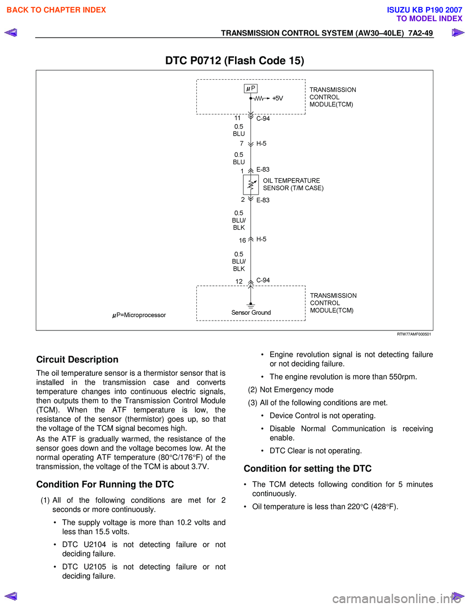
DTC P0712 (Flash Code 15)
RTW 77AMF000501
Circuit Description
The oil temperature sensor is a thermistor sensor that is
installed in the transmission case and converts
temperature changes into continuous electric signals,
then outputs them to the Transmission Control Module
(TCM). W hen the ATF temperature is low, the
resistance of the sensor (thermistor) goes up, so that
the voltage of the TCM signal becomes high.
As the ATF is gradually warmed, the resistance of the
sensor goes down and the voltage becomes low. At the
normal operating ATF temperature (80 °C/176 °F) of the
transmission, the voltage of the TCM is about 3.7V.
Condition For Running the DTC
(1) All of the following conditions are met for 2
seconds or more continuously.
• The supply voltage is more than 10.2 volts and less than 15.5 volts.
• DTC U2104 is not detecting failure or not deciding failure.
• DTC U2105 is not detecting failure or not deciding failure.
• Engine revolution signal is not detecting failure
or not deciding failure.
• The engine revolution is more than 550rpm.
(2) Not Emergency mode
(3) All of the following conditions are met. • Device Control is not operating.
• Disable Normal Communication is receiving enable.
• DTC Clear is not operating.
Condition for setting the DTC
• The TCM detects following condition for 5 minutes continuously.
• Oil temperature is less than 220 °C (428 °F).
BACK TO CHAPTER INDEX
TO MODEL INDEX
ISUZU KB P190 2007