2007 ISUZU KB P190 engine oil
[x] Cancel search: engine oilPage 3612 of 6020
Starting System – V6 Page 6D1-2–4
• Clarify a procedure,
• Present additional information for accomplishing a procedure,
• Give insight into the reasons for performing a procedure in the recommended manner, and / or
Present information that gives the technician the benefit of past experience in accomplishing a procedure with greater
ease.
1.2 Components
Starting System Components
The main components of the starting system are:
• battery,
• wiring,
• ignition switch,
• theft deterrent engine crank inhibitor (a function of the theft deterrent system),
• park / neutral and back-up switch (on vehicles with 4 speed automatic transmission),
• engine control module (ECM),
• start relay,
• solenoid switch, and
• starter motor.
Starter Motor and Solenoid Switch Components
Solenoid Switch
The solenoid switch is used to activate the DC motor and has two windings; the pull-in winding and the hold-in winding.
The pull-in winding has heavier wire and is grounded through the DC motor winding and brushes. The hold-in winding is
grounded through the solenoid casing.
Planetary Drive Train
The planetary drive train consists of an internally toothed ring gear and three planetary gear wheels, which rotate on
sleeve bearings on the planetary drive shaft. The ring gear is keyed into the drive-end housing and is made from
high-grade polyamide with mineral additives.
W hen the starter motor operates, the armature turns the planetary gears inside the fixed planetary ring gear. This drives
the planetary shaft at a reduced speed ratio which turns the drive assembly. A fork lever in the drive-end housing forces
the drive assembly forward to engage with the flexplate / flywheel ring gear on the engine and transmit cranking torque.
An internal clutch allows the drive assembly pinion gear to rotate freely when the engine starts. This prevents the
armature from being driven at excessive speed by the engine.
Armature
The armature shaft is supported at each end by oil absorbent, sintered metal bushes; one in the commutator end shield
and one in the planetary drive shaft. The front end of the armature has a gear profile. This meshes with the three
planetary gear wheels. These in turn, mesh with the internal teeth of the ring gear.
Brushes
A brush plate supports four commutator brushes. This plate is fixed to the commutator end shield with two retaining
screws. Two negative brushes are grounded to the pole housing. The two positive brushes are insulated from the pole
housing and connected to the solenoid switch M terminal, refer to Figure 6D1-2 – 1.
BACK TO CHAPTER INDEX
TO MODEL INDEX
ISUZU KB P190 2007
Page 3628 of 6020
Starting System – V6 Page 6D1-2–20
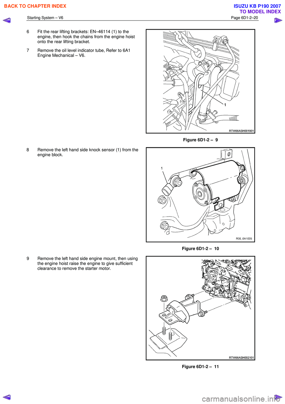
6 Fit the rear lifting brackets: EN–46114 (1) to the
engine, then hook the chains from the engine hoist
onto the rear lifting bracket.
7 Remove the oil level indicator tube, Refer to 6A1 Engine Mechanical – V6.
Figure 6D1-2 – 9
8 Remove the left hand side knock sensor (1) from the engine block.
Figure 6D1-2 – 10
9 Remove the left hand side engine mount, then using the engine hoist raise the engine to give sufficient
clearance to remove the starter motor.
Figure 6D1-2 – 11
BACK TO CHAPTER INDEX
TO MODEL INDEX
ISUZU KB P190 2007
Page 3629 of 6020
Starting System – V6 Page 6D1-2–21
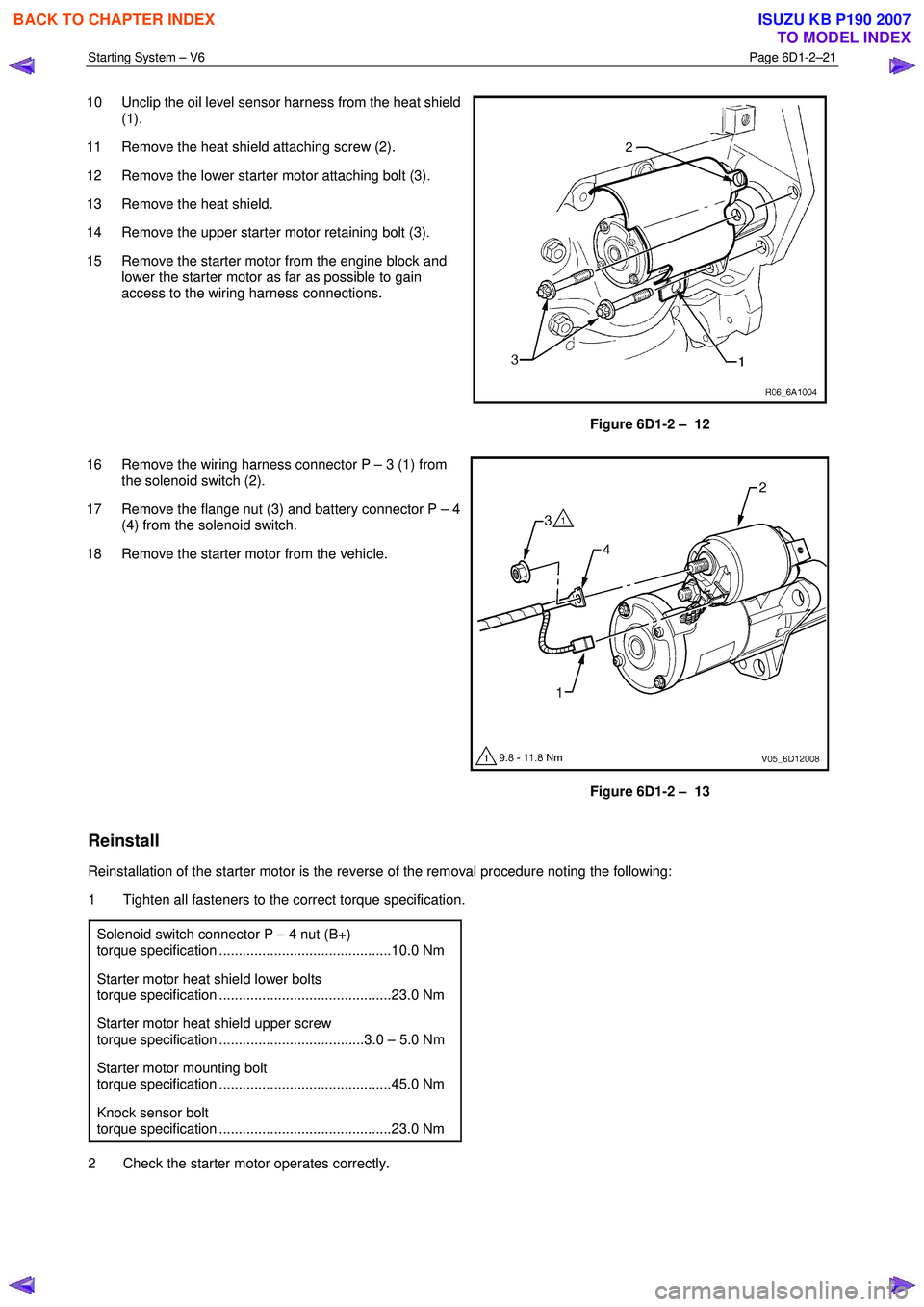
10 Unclip the oil level sensor harness from the heat shield
(1).
11 Remove the heat shield attaching screw (2).
12 Remove the lower starter motor attaching bolt (3).
13 Remove the heat shield.
14 Remove the upper starter motor retaining bolt (3).
15 Remove the starter motor from the engine block and lower the starter motor as far as possible to gain
access to the wiring harness connections.
Figure 6D1-2 – 12
16 Remove the wiring harness connector P – 3 (1) from the solenoid switch (2).
17 Remove the flange nut (3) and battery connector P – 4 (4) from the solenoid switch.
18 Remove the starter motor from the vehicle.
Figure 6D1-2 – 13
Reinstall
Reinstallation of the starter motor is the reverse of the removal procedure noting the following:
1 Tighten all fasteners to the correct torque specification.
Solenoid switch connector P – 4 nut (B+)
torque specification ............................................10.0 Nm
Starter motor heat shield lower bolts
torque specification ............................................23.0 Nm
Starter motor heat shield upper screw
torque specification .....................................3.0 – 5.0 Nm
Starter motor mounting bolt
torque specification ............................................45.0 Nm
Knock sensor bolt
torque specification ............................................23.0 Nm
2 Check the starter motor operates correctly.
BACK TO CHAPTER INDEX
TO MODEL INDEX
ISUZU KB P190 2007
Page 3673 of 6020
Powertrain Interface Module – V6 Page 6E1–12
3 Component Description and
Operation
3.1 Powertrain Interface Module
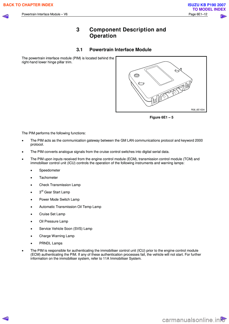
The powertrain interface module (PIM) is located behind the
right-hand lower hinge pillar trim.
Figure 6E1 – 5
The PIM performs the following functions:
• The PIM acts as the communication gateway between the GM LAN communications protocol and keyword 2000
protocol.
• The PIM converts analogue signals from the cruise control switches into digital serial data.
• The PIM upon inputs received from the engine control module (ECM), transmission control module (TCM) and
immobiliser control unit (ICU) controls the operation of the following instruments and warning lamps:
• Speedometer
• Tachometer
• Check Transmission Lamp
• 3
rd Gear Start Lamp
• Power Mode Switch Lamp
• Automatic Transmission Oil Temp Lamp
• Cruise Set Lamp
• Oil Pressure Lamp
• Service Vehicle Soon (SVS) Lamp
• Charge W arning Lamp
• PRNDL Lamps
• The PIM is responsible for authenticating the immobiliser control unit (ICU) prior to the engine control module
(ECM) authenticating the PIM. If any of these authentication processes fail, the vehicle will not start. For further
information on the immobiliser system, refer to 11A Immobiliser System.
BACK TO CHAPTER INDEX
TO MODEL INDEX
ISUZU KB P190 2007
Page 3682 of 6020
Powertrain Interface Module – V6 Page 6E1–21
6.3 Connector Information
PIM Connector Pin Specifications
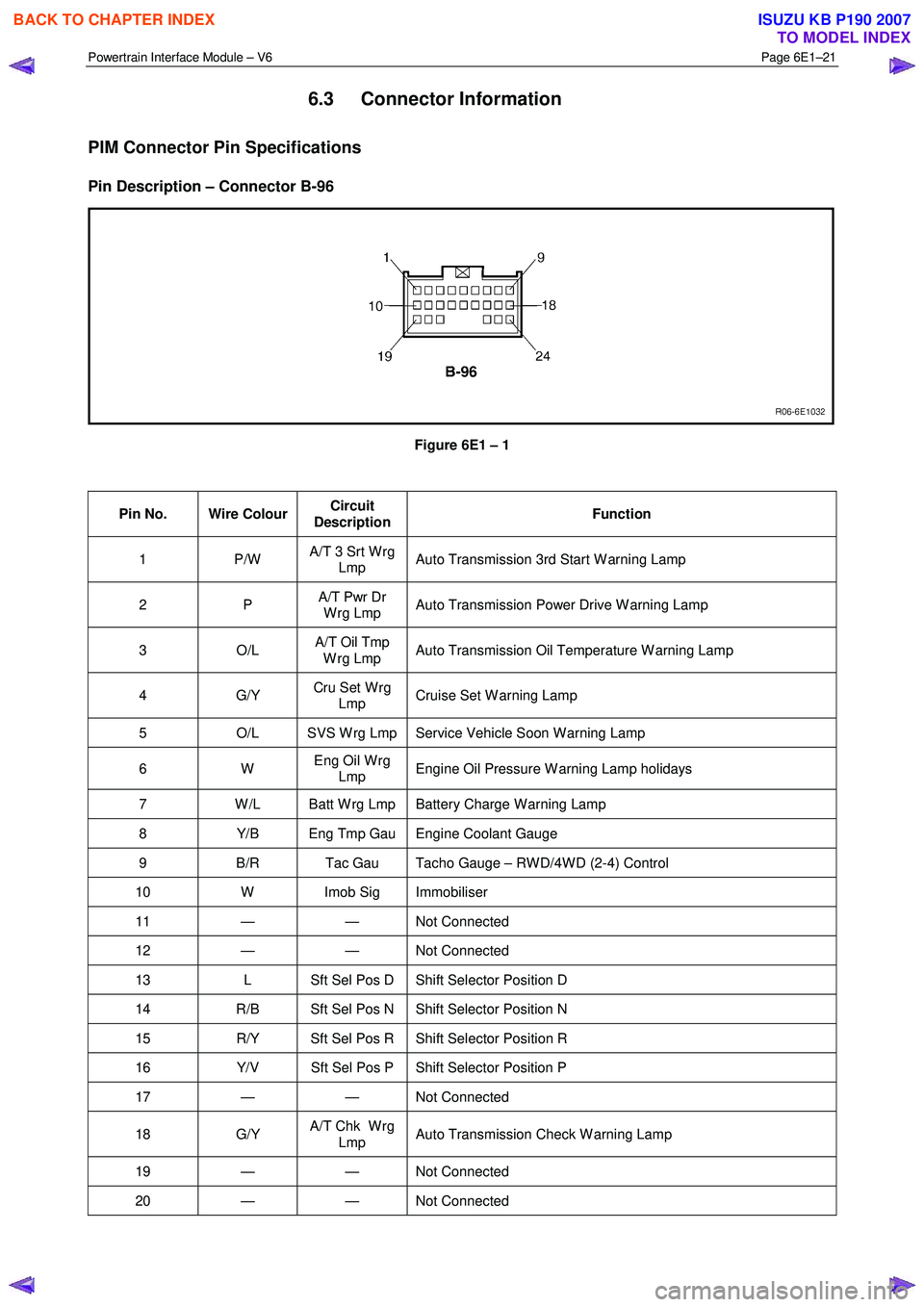
Pin Description – Connector B-96
Figure 6E1 – 1
Pin No. Wire Colour Circuit
Description Function
1 P/W
A/T 3 Srt W rg
Lmp Auto Transmission 3rd Start W arning Lamp
2 P
A/T Pwr Dr
W rg Lmp Auto Transmission Power Drive W arning Lamp
3 O/L A/T Oil Tmp
W rg Lmp Auto Transmission Oil Temperature W arning Lamp
4 G/Y
Cru Set W rg
Lmp Cruise Set W arning Lamp
5
O/L SVS W rg Lmp Service Vehicle Soon W arning Lamp
6 W Eng Oil W rg
Lmp Engine Oil Pressure W arning Lamp holidays
7
W /L Batt W rg Lmp Battery Charge W arning Lamp
8 Y/B Eng Tmp Gau Engine Coolant Gauge
9 B/R Tac Gau Tacho Gauge – RW D/4W D (2-4) Control
10 W Imob Sig Immobiliser
11 — — Not Connected
12 — — Not Connected
13 L Sft Sel Pos D Shift Selector Position D
14 R/B Sft Sel Pos N Shift Selector Position N
15 R/Y Sft Sel Pos R Shift Selector Position R
16 Y/V Sft Sel Pos P Shift Selector Position P
17 — — Not Connected
18 G/Y A/T Chk W rg
Lmp Auto Transmission Check W arning Lamp
19 — — Not
Connected
20 — — Not Connected
BACK TO CHAPTER INDEX
TO MODEL INDEX
ISUZU KB P190 2007
Page 3726 of 6020
Powertrain Interface Module – V6 Page 6E1–65
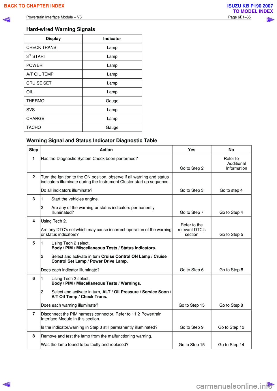
Hard-wired Warning Signals
Display Indicator
CHECK TRANS Lamp
3rd START Lamp
POW ER Lamp
A/T OIL TEMP Lamp
CRUISE SET Lamp
OIL Lamp
THERMO Gauge
SVS Lamp
CHARGE Lamp
TACHO Gauge
Warning Signal and Status Indicator Diagnostic Table
Step Action Yes No
1
Has the Diagnostic System Check been performed?
Go to Step 2 Refer to
Additional
Information
2 Turn the Ignition to the ON position, observe if all warning and status
indicators illuminate during the Instrument Cluster start up sequence.
Do all indicators illuminate? Go to Step 3 Go to step 4
3 1 Start the vehicles engine.
2 Are any of the warning or status indicators permanently illuminated? Go to Step 7 Go to Step 4
4 Using Tech 2.
Are any DTC’s set which may cause incorrect operation of the warning
or status indicators? Refer to the
relevant DTC’s section Go to Step 5
5
1 Using Tech 2 select,
Body / PIM / Miscellaneous Tests / Status Indicators.
2 Select and activate in turn Cruise Control ON Lamp / Cruise
Control Set Lamp / Power Drive Lamp.
Does each indicator illuminate? Go to Step 6 Go to Step 8
6
1 Using Tech 2 select,
Body / PIM / Miscellaneous Tests / Warnings.
2 Select and activate in turn, ALT / Oil Pressure / Service Soon /
A/T Oil Temp / Check Trans.
Does each warning illuminate? Go to Step 15 Go to Step 8
7 Disconnect the PIM harness connector. Refer to 11.2 Powertrain
Interface Module in this section.
Is the indicator/warning in Step 3 still permanently illuminated? Go to Step 9 Go to Step 12
8 Remove and test the lamp from the malfunctioning warning.
W as the lamp found to be faulty and replaced? Go to Step 15 Go to Step 14
BACK TO CHAPTER INDEX
TO MODEL INDEX
ISUZU KB P190 2007
Page 3742 of 6020
Powertrain Interface Module – V6 Page 6E1–81
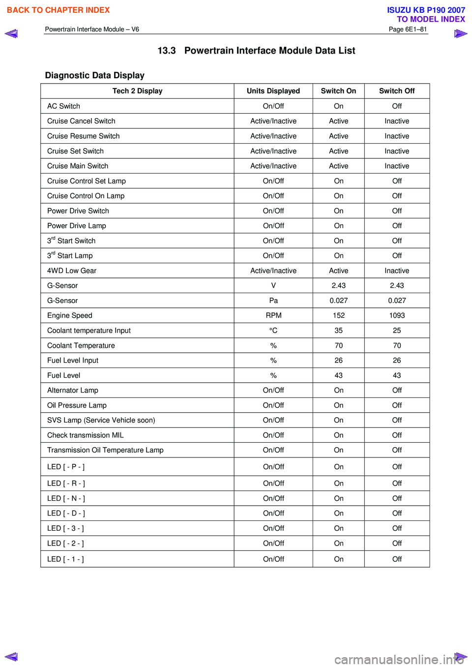
13.3 Powertrain Interface Module Data List
Diagnostic Data Display
Tech 2 Display Units Displayed Switch On Switch Off
AC Switch On/Off On Off
Cruise Cancel Switch Active/Inactive Active Inactive
Cruise Resume Switch Active/Inactive Active Inactive
Cruise Set Switch Active/Inactive Active Inactive
Cruise Main Switch Active/Inactive Active Inactive
Cruise Control Set Lamp On/Off On Off
Cruise Control On Lamp On/Off On Off
Power Drive Switch On/Off On Off
Power Drive Lamp On/Off On Off
3rd Start Switch On/Off On Off
3rd Start Lamp On/Off On Off
4W D Low Gear Active/Inactive Active Inactive
G-Sensor V 2.43 2.43
G-Sensor Pa 0.027 0.027
Engine Speed RPM 152 1093
Coolant temperature Input °C 35 25
Coolant Temperature % 70 70
Fuel Level Input % 26 26
Fuel Level % 43 43
Alternator Lamp On/Off On Off
Oil Pressure Lamp On/Off On Off
SVS Lamp (Service Vehicle soon) On/Off On Off
Check transmission MIL On/Off On Off
Transmission Oil Temperature Lamp On/Off On Off
LED [ - P - ] On/Off On Off
LED [ - R - ] On/Off On Off
LED [ - N - ] On/Off On Off
LED [ - D - ] On/Off On Off
LED [ - 3 - ] On/Off On Off
LED [ - 2 - ] On/Off On Off
LED [ - 1 - ] On/Off On Off
BACK TO CHAPTER INDEX
TO MODEL INDEX
ISUZU KB P190 2007
Page 3751 of 6020
Exhaust System – V6 Page 6F – 3
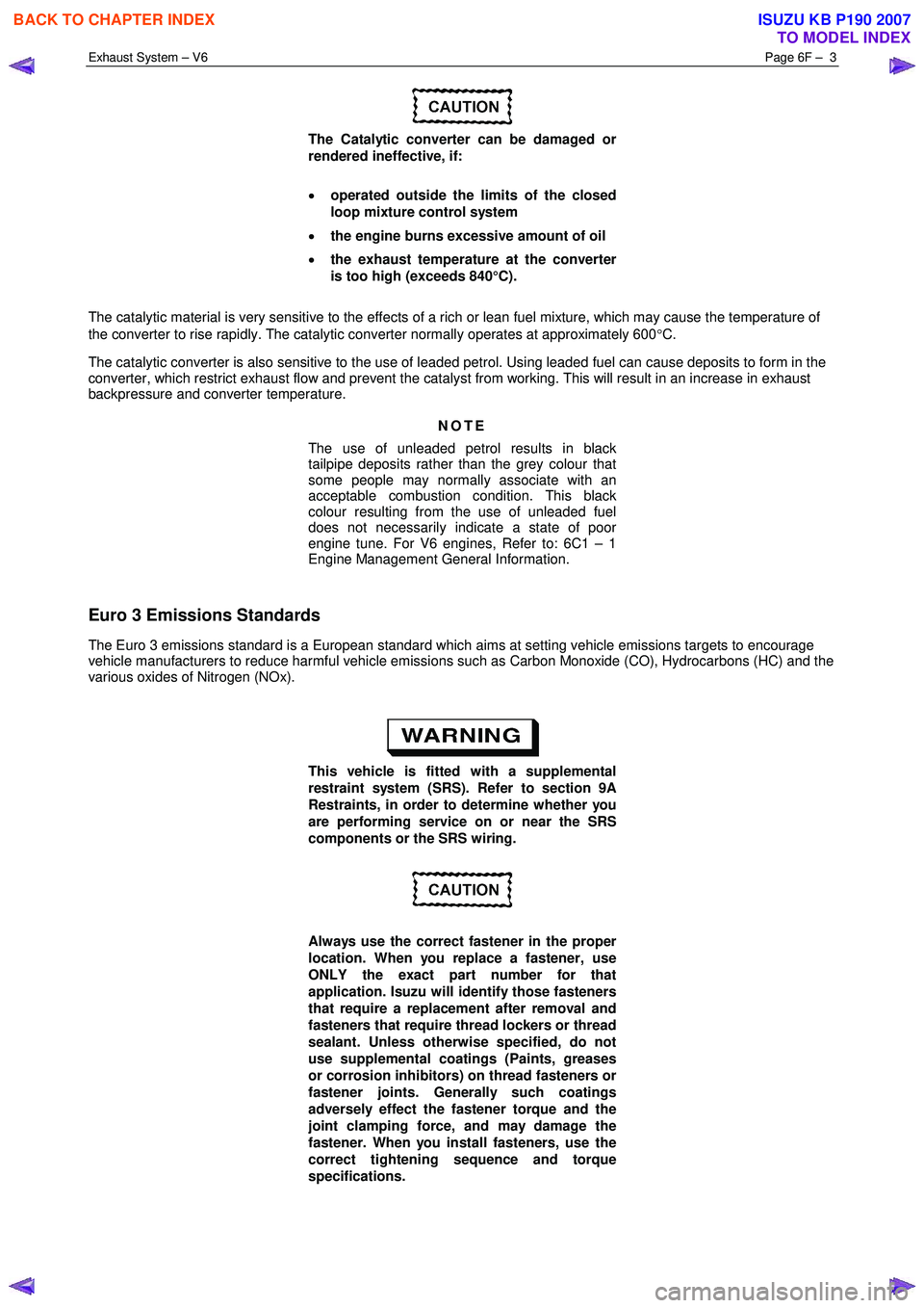
The Catalytic converter can be damaged or
rendered ineffective, if:
• operated outside the limits of the closed
loop mixture control system
• the engine burns excessive amount of oil
• the exhaust temperature at the converter
is too high (exceeds 840°C).
The catalytic material is very sensitive to the effects of a rich or lean fuel mixture, which may cause the temperature of
the converter to rise rapidly. The catalytic converter normally operates at approximately 600 °C.
The catalytic converter is also sensitive to the use of leaded petrol. Using leaded fuel can cause deposits to form in the
converter, which restrict exhaust flow and prevent the catalyst from working. This will result in an increase in exhaust
backpressure and converter temperature.
NOTE
The use of unleaded petrol results in black
tailpipe deposits rather than the grey colour that
some people may normally associate with an
acceptable combustion condition. This black
colour resulting from the use of unleaded fuel
does not necessarily indicate a state of poor
engine tune. For V6 engines, Refer to: 6C1 – 1
Engine Management General Information.
Euro 3 Emissions Standards
The Euro 3 emissions standard is a European standard which aims at setting vehicle emissions targets to encourage
vehicle manufacturers to reduce harmful vehicle emissions such as Carbon Monoxide (CO), Hydrocarbons (HC) and the
various oxides of Nitrogen (NOx).
This vehicle is fitted with a supplemental
restraint system (SRS). Refer to section 9A
Restraints, in order to determine whether you
are performing service on or near the SRS
components or the SRS wiring.
Always use the correct fastener in the proper
location. When you replace a fastener, use
ONLY the exact part number for that
application. Isuzu will identify those fasteners
that require a replacement after removal and
fasteners that require thread lockers or thread
sealant. Unless otherwise specified, do not
use supplemental coatings (Paints, greases
or corrosion inhibitors) on thread fasteners or
fastener joints. Generally such coatings
adversely effect the fastener torque and the
joint clamping force, and may damage the
fastener. When you install fasteners, use the
correct tightening sequence and torque
specifications.
BACK TO CHAPTER INDEX
TO MODEL INDEX
ISUZU KB P190 2007