2007 ISUZU KB P190 engine oil
[x] Cancel search: engine oilPage 3581 of 6020
Engine Management – V6 – Service Operations Page 6C1-3–57
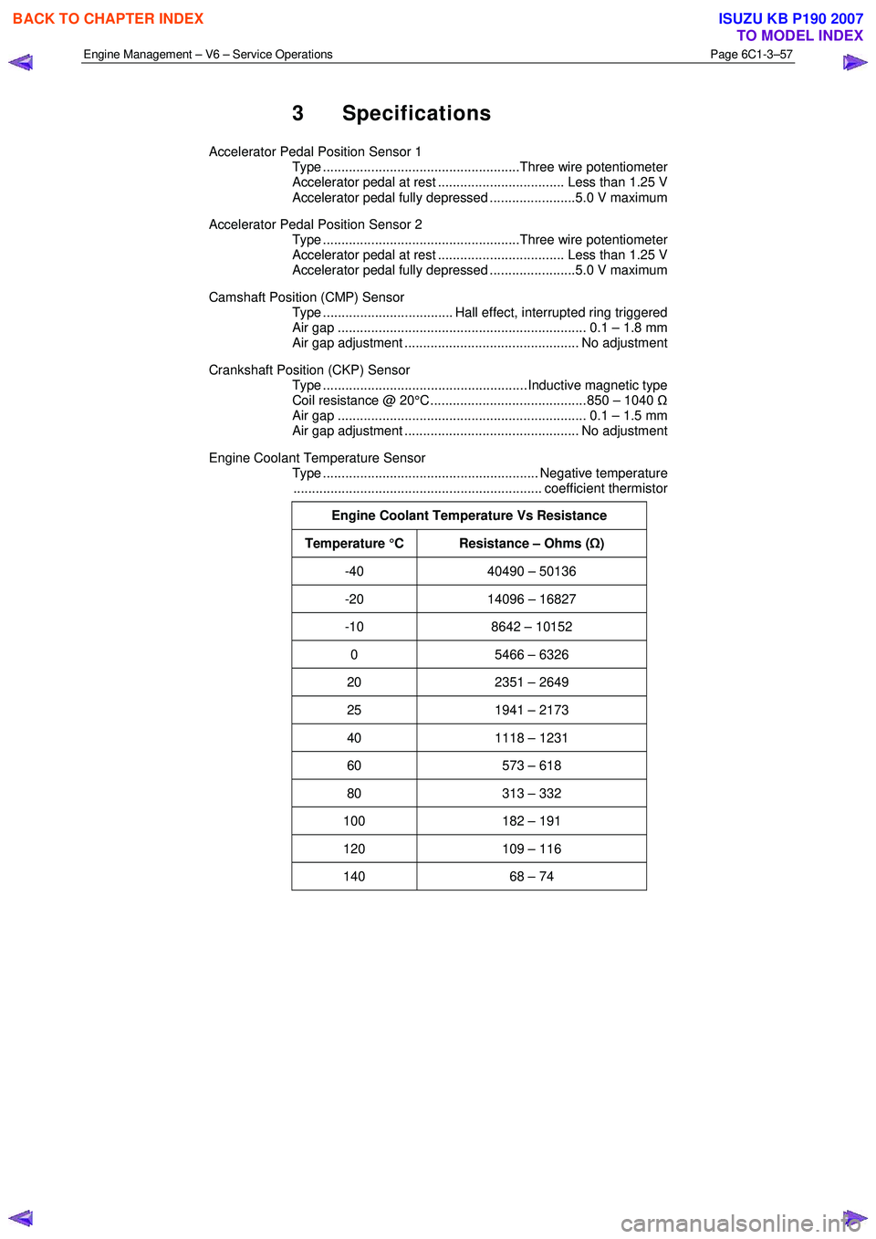
3 Specifications
Accelerator Pedal Position Sensor 1
Type .....................................................Three wire potentiometer
Accelerator pedal at rest .................................. Less than 1.25 V
Accelerator pedal fully depressed .......................5.0 V maximum
Accelerator Pedal Position Sensor 2
Type .....................................................Three wire potentiometer
Accelerator pedal at rest .................................. Less than 1.25 V
Accelerator pedal fully depressed .......................5.0 V maximum
Camshaft Position (CMP) Sensor
Type ................................... Hall effect, interrupted ring triggered
Air gap ................................................................... 0.1 – 1.8 mm
Air gap adjustment ............................................... No adjustment
Crankshaft Position (CKP) Sensor
Type ....................................................... Inductive magnetic type
Coil resistance @ 20°C .......................................... 850 – 1040 Ω
Air gap ................................................................... 0.1 – 1.5 mm
Air gap adjustment ............................................... No adjustment
Engine Coolant Temperature Sensor
Type .......................................................... Negative temperature
................................................................... coefficient thermistor
Engine Coolant Temperature Vs Resistance
Temperature °C Resistance – Ohms ( Ω)
-40 40490 – 50136
-20 14096 – 16827
-10 8642 – 10152
0 5466 – 6326
20 2351 – 2649
25 1941 – 2173
40 1118 – 1231
60 573 – 618
80 313 – 332
100 182 – 191
120 109 – 116
140 68 – 74
BACK TO CHAPTER INDEX
TO MODEL INDEX
ISUZU KB P190 2007
Page 3582 of 6020
Engine Management – V6 – Service Operations Page 6C1-3–58
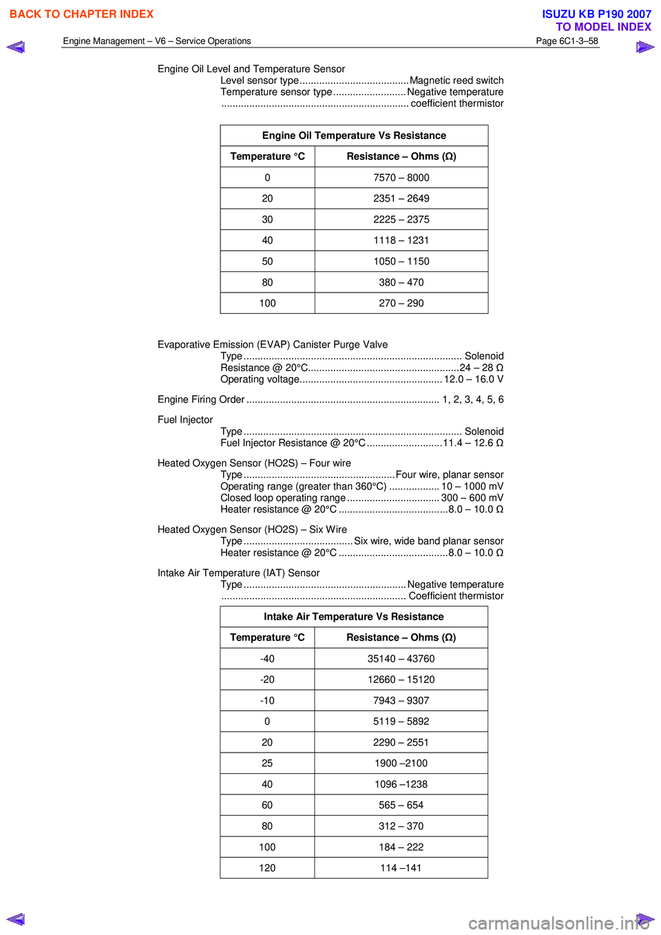
Engine Oil Level and Temperature Sensor
Level sensor type ....................................... Magnetic reed switch
Temperature sensor type .......................... Negative temperature
................................................................... coefficient thermistor
Engine Oil Temperature Vs Resistance
Temperature °C Resistance – Ohms ( Ω)
0 7570 – 8000
20 2351 – 2649
30 2225 – 2375
40 1118 – 1231
50 1050 – 1150
80 380 – 470
100 270 – 290
Evaporative Emission (EVAP) Canister Purge Valve
Type .............................................................................. Solenoid
Resistance @ 20°C...................................................... 24 – 28 Ω
Operating voltage................................................... 12.0 – 16.0 V
Engine Firing Order ..................................................................... 1, 2, 3, 4, 5, 6
Fuel Injector
Type .............................................................................. Solenoid
Fuel Injector Resistance @ 20°C ........................... 11.4 – 12.6 Ω
Heated Oxygen Sensor (HO2S) – Four wire
Type ...................................................... Four wire, planar sensor
Operating range (greater than 360°C) .................. 10 – 1000 mV
Closed loop operating range ................................. 300 – 600 mV
Heater resistance @ 20°C ....................................... 8.0 – 10.0 Ω
Heated Oxygen Sensor (HO2S) – Six W ire
Type ....................................... Six wire, wide band planar sensor
Heater resistance @ 20°C ....................................... 8.0 – 10.0 Ω
Intake Air Temperature (IAT) Sensor
Type .......................................................... Negative temperature
.................................................................. Coefficient thermistor
Intake Air Temperature Vs Resistance
Temperature °C Resistance – Ohms ( Ω)
-40 35140 – 43760
-20 12660 – 15120
-10 7943 – 9307
0 5119 – 5892
20 2290 – 2551
25 1900 –2100
40 1096 –1238
60 565 – 654
80 312 – 370
100 184 – 222
120 114 –141
BACK TO CHAPTER INDEX
TO MODEL INDEX
ISUZU KB P190 2007
Page 3584 of 6020
Engine Management – V6 – Service Operations Page 6C1-3–60
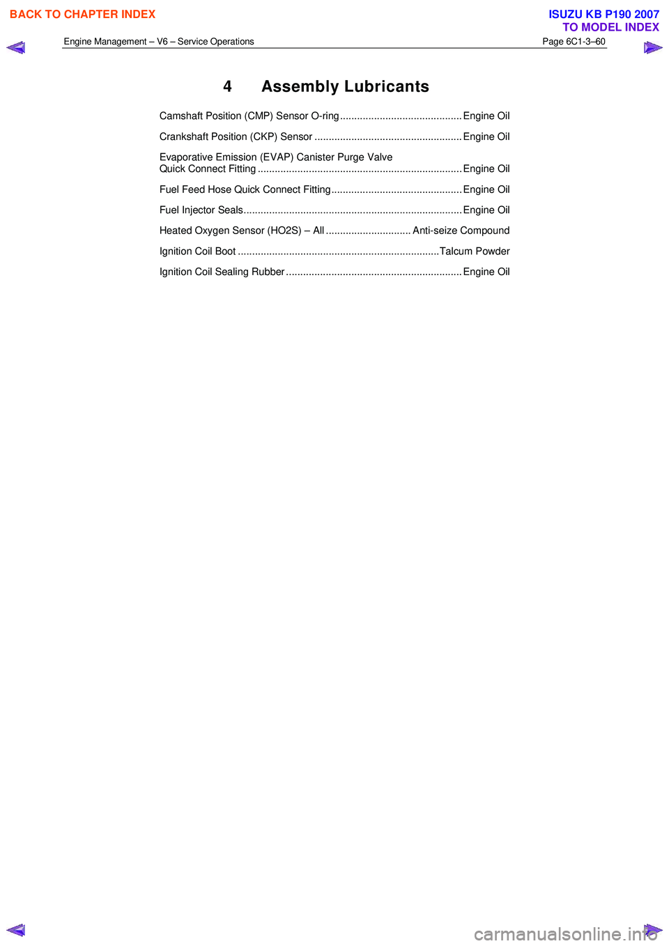
4 Assembly Lubricants
Camshaft Position (CMP) Sensor O-ring ........................................... Engine Oil
Crankshaft Position (CKP) Sensor .................................................... Engine Oil
Evaporative Emission (EVAP) Canister Purge Valve
Quick Connect Fitting ........................................................................ Engine Oil
Fuel Feed Hose Quick Connect Fitting .............................................. Engine Oil
Fuel Injector Seals............................................................................. Engine Oil
Heated Oxygen Sensor (HO2S) – All .............................. Anti-seize Compound
Ignition Coil Boot .......................................................................Talcum Powder
Ignition Coil Sealing Rubber .............................................................. Engine Oil
BACK TO CHAPTER INDEX
TO MODEL INDEX
ISUZU KB P190 2007
Page 3585 of 6020
Engine Management – V6 – Service Operations Page 6C1-3–61
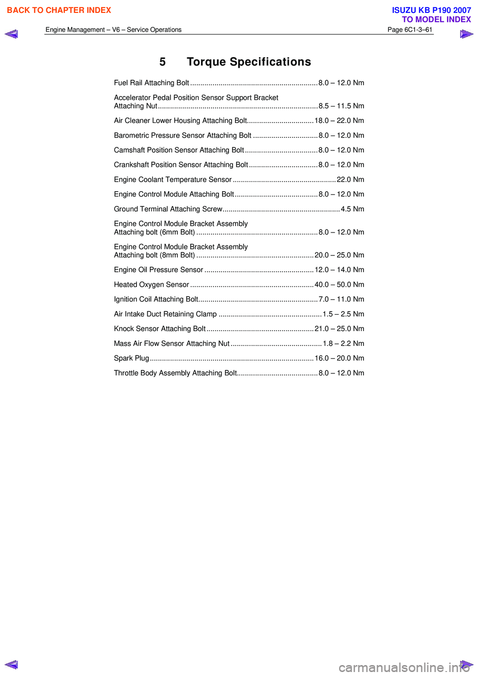
5 Torque Specifications
Fuel Rail Attaching Bolt ............................................................... 8.0 – 12.0 Nm
Accelerator Pedal Position Sensor Support Bracket
Attaching Nut ............................................................................... 8.5 – 11.5 Nm
Air Cleaner Lower Housing Attaching Bolt................................. 18.0 – 22.0 Nm
Barometric Pressure Sensor Attaching Bolt ................................ 8.0 – 12.0 Nm
Camshaft Position Sensor Attaching Bolt .................................... 8.0 – 12.0 Nm
Crankshaft Position Sensor Attaching Bolt .................................. 8.0 – 12.0 Nm
Engine Coolant Temperature Sensor ................................................... 22.0 Nm
Engine Control Module Attaching Bolt ......................................... 8.0 – 12.0 Nm
Ground Terminal Attaching Screw.......................................................... 4.5 Nm
Engine Control Module Bracket Assembly
Attaching bolt (6mm Bolt) ............................................................ 8.0 – 12.0 Nm
Engine Control Module Bracket Assembly
Attaching bolt (8mm Bolt) .......................................................... 20.0 – 25.0 Nm
Engine Oil Pressure Sensor ...................................................... 12.0 – 14.0 Nm
Heated Oxygen Sensor ............................................................. 40.0 – 50.0 Nm
Ignition Coil Attaching Bolt........................................................... 7.0 – 11.0 Nm
Air Intake Duct Retaining Clamp ................................................... 1.5 – 2.5 Nm
Knock Sensor Attaching Bolt ..................................................... 21.0 – 25.0 Nm
Mass Air Flow Sensor Attaching Nut ............................................. 1.8 – 2.2 Nm
Spark Plug ................................................................................. 16.0 – 20.0 Nm
Throttle Body Assembly Attaching Bolt........................................ 8.0 – 12.0 Nm
BACK TO CHAPTER INDEX
TO MODEL INDEX
ISUZU KB P190 2007
Page 3586 of 6020

Engine Management – V6 – Service Operations Page 6C1-3–62
6 Special Tools
Tool Number Illustration Description Tool Classification
7000086i
Tech 2 scan tool
Used for diagnosis of vehicle electrical
systems.
Previously released. Mandatory
3588
Digital Multimeter
Previously released as j 39200, 3545
GM. Available
J 35616
Connector Test Adaptor Kit
Used when carrying out electrical
diagnostic circuit checks.
Previously released. Desirable
J 34142-a
Un-powered Test Lamp
Previously released as CT-40-C and
also commercially available.
Must have a current draw less than
0.3 A. Mandatory
J 34730-2C
Injector Test Light
Used to check for power and the
control circuit of the fuel injector, for
proper operation.
Also previously released as
ST- 8329 Mandatory
J 39021 Fuel Injector Coil / Balance Tester
Used in conjunction with a DMM for
testing the fuel injector coil windings
and for injector balance testing.
Previously released Mandatory
J 44602 Injector Test Adapter
Mandatory
BACK TO CHAPTER INDEX
TO MODEL INDEX
ISUZU KB P190 2007
Page 3587 of 6020
Engine Management – V6 – Service Operations Page 6C1-3–63
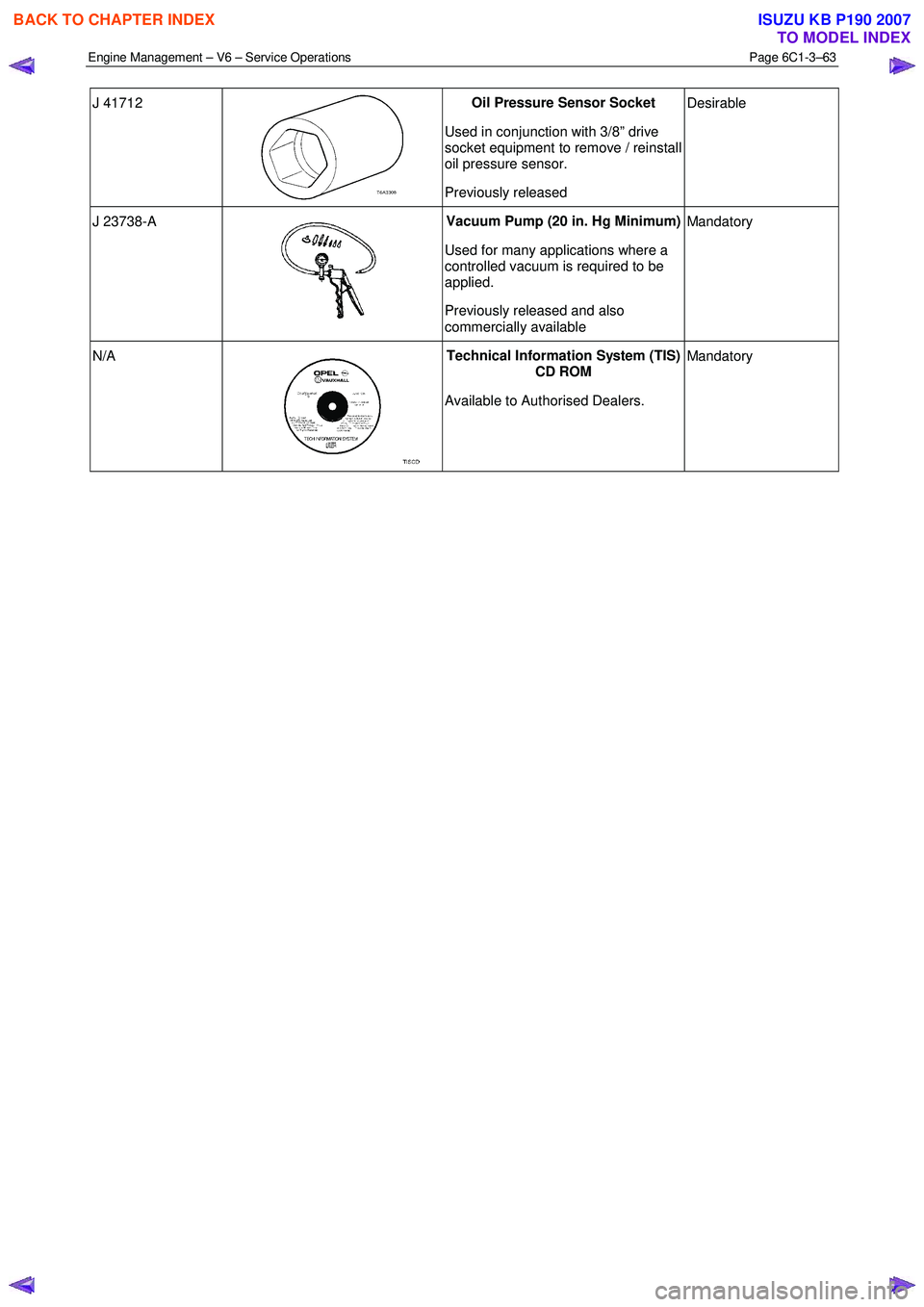
J 41712
Oil Pressure Sensor Socket
Used in conjunction with 3/8” drive
socket equipment to remove / reinstall
oil pressure sensor.
Previously released Desirable
J 23738-A
Vacuum Pump (20 in. Hg Minimum)
Used for many applications where a
controlled vacuum is required to be
applied.
Previously released and also
commercially available Mandatory
N/A
Technical Information System (TIS)
CD ROM
Available to Authorised Dealers. Mandatory
BACK TO CHAPTER INDEX
TO MODEL INDEX
ISUZU KB P190 2007
Page 3590 of 6020
Charging System – V6 Page 6D1-1-3
1 General Information
1.1 Components
Generator
The Mitsubishi generator can be identified visually by its two lower and one upper mounting lugs.
It is mounted to the lower right-hand side of the engine block. It is driven by the same drive belt that drives other engine
ancillaries and requires no periodic drive belt adjustment.
The generator has three phases, incorporating a rotor with six pole pairs fitted and two internal cooling fans; one on the
drive-end and one on the slip-ring end. The rotor is supported by ball bearings in both the drive and slip-ring end
housings. Surrounding the rotor is a stator, which has a three phase delta connected output winding construction on a
ring shaped lamination pack.
The output of the stator winding is rectified by eight diodes that are contained within the slip-ring end housing. Excitation
current is supplied to the rotor field coil via the voltage regulator, the brushes and slip-rings. The electronic voltage
regulator requires no adjustment in service.
The generator has four external connections (refer to Figure 6D1-1 1):
• Generator – Terminal P-9 to the battery positive terminal P-1 via fuse SBF1,
• Generator – E-4 pin 1 to the ECM connection E-60 pin 43 – regulator monitoring,
• Generator – E-4 pin 2 to the ECM connection E60 pin 21 – battery voltage sensing, and
• ground connection via the installation bolts.
Generator Types
The vehicle is fitted with a 120 amp generator.
BACK TO CHAPTER INDEX
TO MODEL INDEX
ISUZU KB P190 2007
Page 3611 of 6020
Starting System – V6 Page 6D1-2–3
1 General Information
All HFV6 engines are fitted with a Mitsubishi starter motor. This consists of a solenoid switch on a DC motor. The motor
has permanent magnet excitation, which has the advantage of low weight a with high output torque and is visually
identifiable by the absence of pole-shoe retaining screws.
The starter motor does not have field coil windings or pole shoes. These parts have been replaced by six permanent
magnets that are held in the pole housing by clips. The positive brushes are now part of the brush plate assembly.
The solenoid switch is the only component of the starter motor assembly that is serviced separately. If any other parts
require replacement, the starter motor must be replaced.
1.1 WARNING, CAUTION and NOTES
This Section contains various W ARNINGS, CAUTIONS and NOTE statements that you must observe carefully to reduce
the risk of death or injury during service, repair procedures or vehicle operation. Incorrect service or repair procedures
may damage the vehicle or cause operational faults. W ARNINGS, CAUTION and NOTE statements are not exhaustive.
HOLDEN LTD can not possibly warn of all the potentially hazardous consequences of failure to follow these instructions.
Definition of WARNING, CAUTION and NOTE Statements
Diagnosis and repair procedures in this Section contain both general and specific W ARNING, CAUTION and NOTE
statements. HOLDEN LTD is dedicated to the presentation of service information that helps the technician to diagnose
and repair the systems necessary for proper operation of the vehicle. Certain procedures may present a hazard to the
technician if they are not followed in the recommended manner. W ARNING, CAUTION and NOTE statements are
designed to help prevent these hazards from occurring, but not all hazards can be foreseen.
WARNING defined
A W ARNING statement immediately precedes an operating procedure or maintenance practice which, if not correctly
followed, could result in death or injury. A W ARNING statement alerts you to take necessary action or not to take a
prohibited action. If a W ARNING statement is ignored, the following consequences may occur:
• Death or injury to the technician or other personnel working on the vehicle,
• Death or injury to other people in or near the workplace area, and / or
• Death or injury to the driver / or passenger(s) of the vehicle or other people, if the vehicle has been improperly
repaired.
CAUTION defined
A CAUTION statement immediately precedes an operating procedure or maintenance practice which, if not correctly
followed, could result in damage to or destruction of equipment, or corruption of data. If a CAUTION statement is ignored,
the following consequences may occur:
• Damage to the vehicle,
• Unnecessary vehicle repairs or component replacement,
• Faulty operation or performance of any system or component being repaired,
• Damage to any system or components which depend on the proper operation of the system or component being
repaired,
• Faulty operation or performance of any systems or components which depend on the proper operation or
performance of the system or component under repair,
• Damage to fasteners, basic tools or special tools and / or
• Leakage of coolant, lubricant or other vital fluids.
NOTE defined
A NOTE statement immediately precedes or follows an operating procedure, maintenance practice or condition that
requires highlighting. A NOTE statement also emphasises necessary characteristics of a diagnostic or repair procedure.
A NOTE statement is designed to:
BACK TO CHAPTER INDEX
TO MODEL INDEX
ISUZU KB P190 2007