2007 INFINITI QX56 oil temperature
[x] Cancel search: oil temperaturePage 2106 of 3061
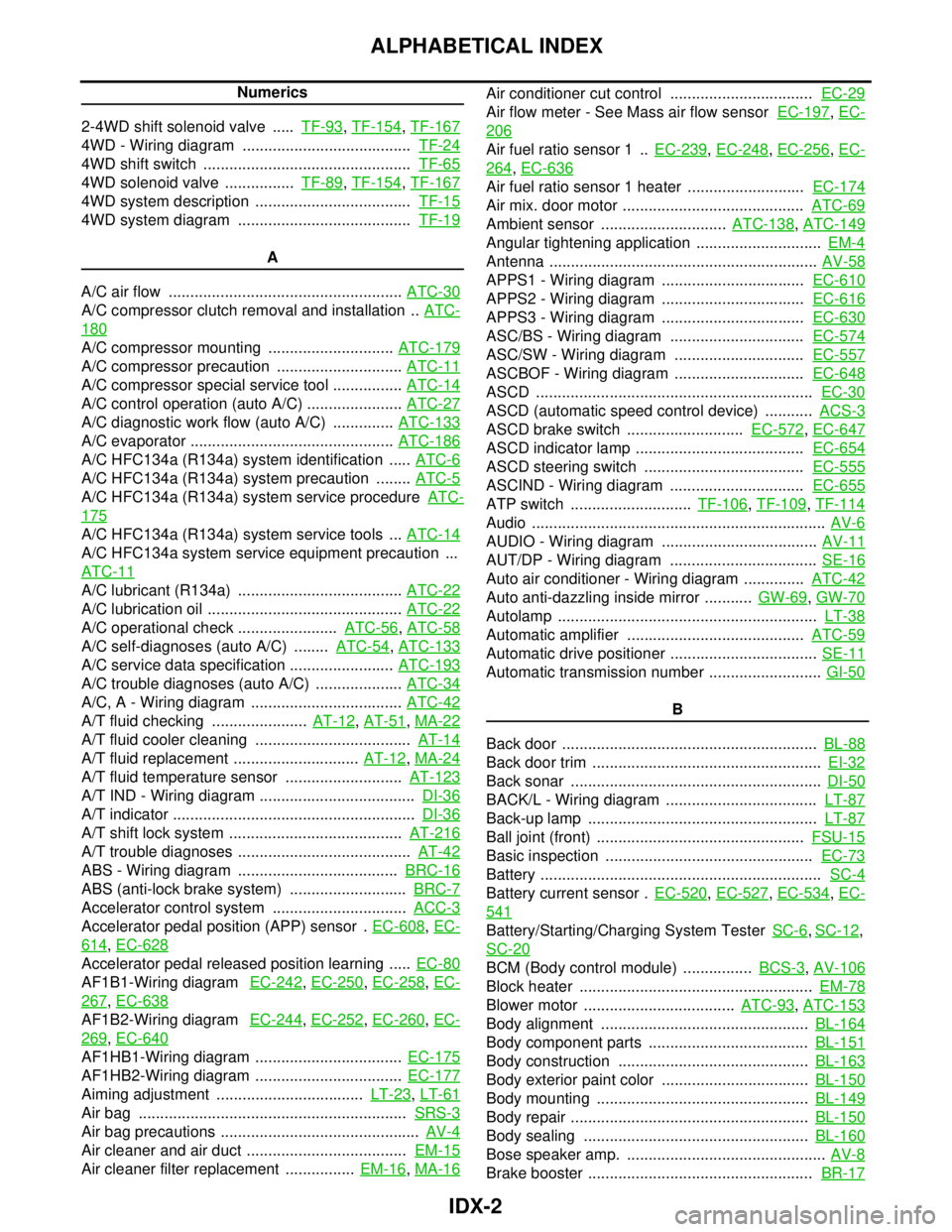
IDX-2
ALPHABETICAL INDEX
Numerics
2-4WD shift solenoid valve ..... TF-93
, TF-154, TF-167
4WD - Wiring diagram ....................................... TF-24
4WD shift switch ................................................ TF-65
4WD solenoid valve ................ TF-89, TF-154, TF-167
4WD system description .................................... TF-15
4WD system diagram ........................................ TF-19
A
A/C air flow ...................................................... ATC-30
A/C compressor clutch removal and installation .. ATC-
180
A/C compressor mounting ............................. ATC-179
A/C compressor precaution ............................. ATC-11
A/C compressor special service tool ................ ATC-14
A/C control operation (auto A/C) ...................... ATC-27
A/C diagnostic work flow (auto A/C) .............. ATC-133
A/C evaporator ............................................... ATC-186
A/C HFC134a (R134a) system identification ..... ATC-6
A/C HFC134a (R134a) system precaution ........ ATC-5
A/C HFC134a (R134a) system service procedure ATC-
175
A/C HFC134a (R134a) system service tools ... ATC-14
A/C HFC134a system service equipment precaution ...
ATC-11
A/C lubricant (R134a) ...................................... ATC-22
A/C lubrication oil ............................................. ATC-22
A/C operational check ....................... ATC-56, ATC-58
A/C self-diagnoses (auto A/C) ........ ATC-54, ATC-133
A/C service data specification ........................ ATC-193
A/C trouble diagnoses (auto A/C) .................... ATC-34
A/C, A - Wiring diagram ................................... ATC-42
A/T fluid checking ...................... AT-12, AT-51, MA-22
A/T fluid cooler cleaning .................................... AT-14
A/T fluid replacement ............................. AT-12, MA-24
A/T fluid temperature sensor ........................... AT-123
A/T IND - Wiring diagram .................................... DI-36
A/T indicator ........................................................ DI-36
A/T shift lock system ........................................ AT-216
A/T trouble diagnoses ........................................ AT-42
ABS - Wiring diagram ..................................... BRC-16
ABS (anti-lock brake system) ........................... BRC-7
Accelerator control system ............................... ACC-3
Accelerator pedal position (APP) sensor . EC-608, EC-
614, EC-628
Accelerator pedal released position learning ..... EC-80
AF1B1-Wiring diagram EC-242, EC-250, EC-258, EC-
267, EC-638
AF1B2-Wiring diagram EC-244, EC-252, EC-260, EC-
269, EC-640
AF1HB1-Wiring diagram .................................. EC-175
AF1HB2-Wiring diagram .................................. EC-177
Aiming adjustment .................................. LT-23, LT-61
Air bag .............................................................. SRS-3
Air bag precautions .............................................. AV-4
Air cleaner and air duct ..................................... EM-15
Air cleaner filter replacement ................ EM-16, MA-16
Air conditioner cut control ................................. EC-29
Air flow meter - See Mass air flow sensor EC-197, EC-
206
Air fuel ratio sensor 1 .. EC-239, EC-248, EC-256, EC-
264, EC-636
Air fuel ratio sensor 1 heater ........................... EC-174
Air mix. door motor .......................................... ATC-69
Ambient sensor ............................. ATC-138, ATC-149
Angular tightening application ............................. EM-4
Antenna .............................................................. AV-58
APPS1 - Wiring diagram ................................. EC-610
APPS2 - Wiring diagram ................................. EC-616
APPS3 - Wiring diagram ................................. EC-630
ASC/BS - Wiring diagram ............................... EC-574
ASC/SW - Wiring diagram .............................. EC-557
ASCBOF - Wiring diagram .............................. EC-648
ASCD ................................................................ EC-30
ASCD (automatic speed control device) ........... ACS-3
ASCD brake switch ........................... EC-572, EC-647
ASCD indicator lamp ....................................... EC-654
ASCD steering switch ..................................... EC-555
ASCIND - Wiring diagram ............................... EC-655
ATP switch ............................ TF-106, TF-109, TF-114
Audio .................................................................... AV-6
AUDIO - Wiring diagram .................................... AV-11
AUT/DP - Wiring diagram .................................. SE-16
Auto air conditioner - Wiring diagram .............. ATC-42
Auto anti-dazzling inside mirror ........... GW-69, GW-70
Autolamp ............................................................ LT-38
Automatic amplifier ......................................... ATC-59
Automatic drive positioner .................................. SE-11
Automatic transmission number .......................... GI-50
B
Back door ........................................................... BL-88
Back door trim ..................................................... EI-32
Back sonar .......................................................... DI-50
BACK/L - Wiring diagram ................................... LT-87
Back-up lamp ..................................................... LT-87
Ball joint (front) ................................................ FSU-15
Basic inspection ................................................ EC-73
Battery ................................................................. SC-4
Battery current sensor . EC-520, EC-527, EC-534, EC-
541
Battery/Starting/Charging System Tester SC-6, SC-12,
SC-20
BCM (Body control module) ................ BCS-3, AV-106
Block heater ...................................................... EM-78
Blower motor ................................... ATC-93, ATC-153
Body alignment ................................................ BL-164
Body component parts ..................................... BL-151
Body construction ............................................ BL-163
Body exterior paint color .................................. BL-150
Body mounting ................................................. BL-149
Body repair ....................................................... BL-150
Body sealing .................................................... BL-160
Bose speaker amp. .............................................. AV-8
Brake booster .................................................... BR-17
Page 2108 of 3061
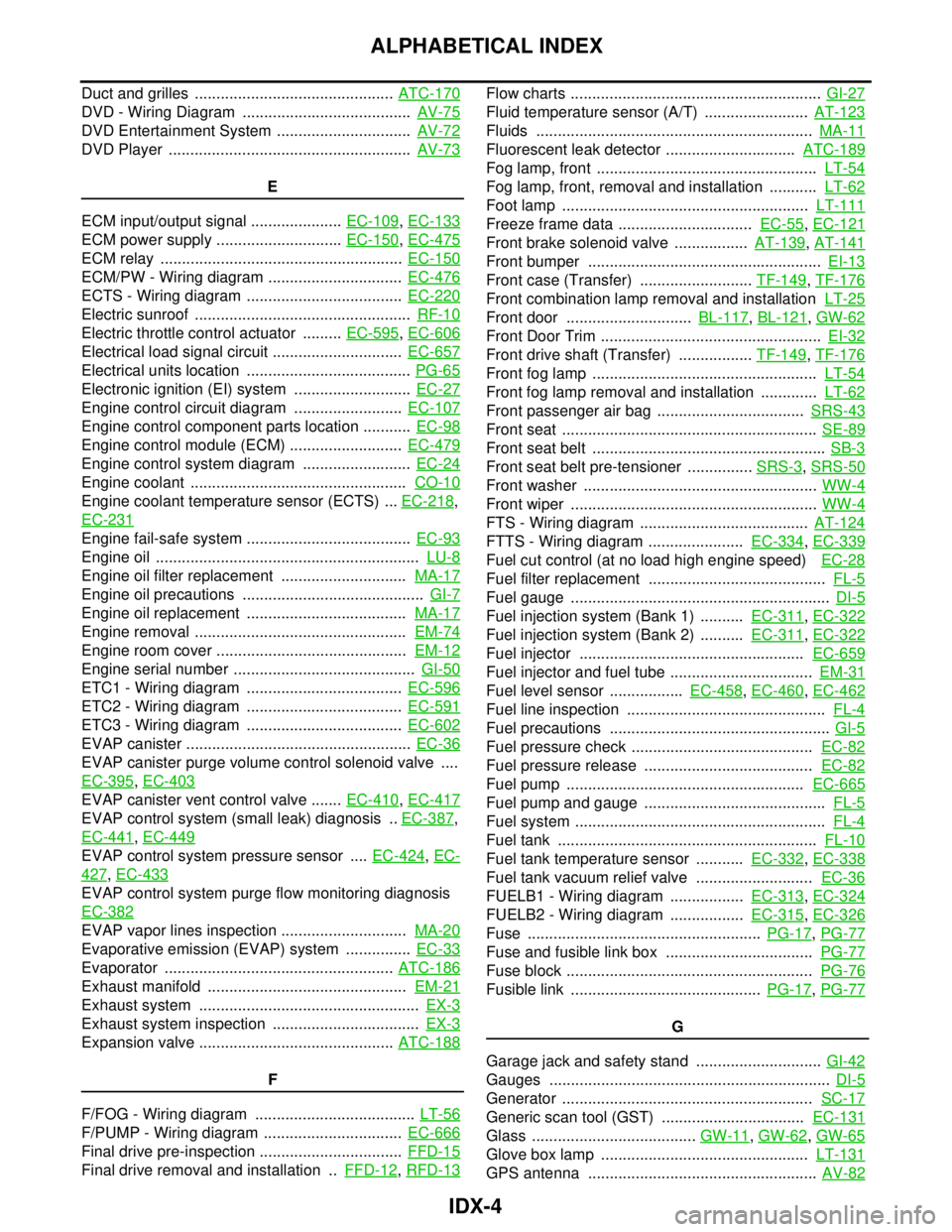
IDX-4
ALPHABETICAL INDEX
Duct and grilles .............................................. ATC-170
DVD - Wiring Diagram ....................................... AV-75
DVD Entertainment System ............................... AV-72
DVD Player ........................................................ AV-73
E
ECM input/output signal ..................... EC-109
, EC-133
ECM power supply ............................. EC-150, EC-475
ECM relay ........................................................ EC-150
ECM/PW - Wiring diagram ............................... EC-476
ECTS - Wiring diagram .................................... EC-220
Electric sunroof .................................................. RF-10
Electric throttle control actuator ......... EC-595, EC-606
Electrical load signal circuit .............................. EC-657
Electrical units location ...................................... PG-65
Electronic ignition (EI) system ........................... EC-27
Engine control circuit diagram ......................... EC-107
Engine control component parts location ........... EC-98
Engine control module (ECM) .......................... EC-479
Engine control system diagram ......................... EC-24
Engine coolant .................................................. CO-10
Engine coolant temperature sensor (ECTS) ... EC-218,
EC-231
Engine fail-safe system ...................................... EC-93
Engine oil ............................................................. LU-8
Engine oil filter replacement ............................. MA-17
Engine oil precautions .......................................... GI-7
Engine oil replacement ..................................... MA-17
Engine removal ................................................. EM-74
Engine room cover ............................................ EM-12
Engine serial number .......................................... GI-50
ETC1 - Wiring diagram .................................... EC-596
ETC2 - Wiring diagram .................................... EC-591
ETC3 - Wiring diagram .................................... EC-602
EVAP canister .................................................... EC-36
EVAP canister purge volume control solenoid valve ....
EC-395
, EC-403
EVAP canister vent control valve ....... EC-410, EC-417
EVAP control system (small leak) diagnosis .. EC-387,
EC-441
, EC-449
EVAP control system pressure sensor .... EC-424, EC-
427, EC-433
EVAP control system purge flow monitoring diagnosis
EC-382
EVAP vapor lines inspection ............................. MA-20
Evaporative emission (EVAP) system ............... EC-33
Evaporator ..................................................... ATC-186
Exhaust manifold .............................................. EM-21
Exhaust system ................................................... EX-3
Exhaust system inspection .................................. EX-3
Expansion valve ............................................. ATC-188
F
F/FOG - Wiring diagram ..................................... LT-56
F/PUMP - Wiring diagram ................................ EC-666
Final drive pre-inspection ................................. FFD-15
Final drive removal and installation .. FFD-12, RFD-13
Flow charts .......................................................... GI-27
Fluid temperature sensor (A/T) ........................ AT-123
Fluids ................................................................ MA-11
Fluorescent leak detector .............................. ATC-189
Fog lamp, front ................................................... LT-54
Fog lamp, front, removal and installation ........... LT-62
Foot lamp ......................................................... LT-111
Freeze frame data ............................... EC-55, EC-121
Front brake solenoid valve ................. AT-139, AT-141
Front bumper ...................................................... EI-13
Front case (Transfer) .......................... TF-149, TF-176
Front combination lamp removal and installation LT-25
Front door ............................. BL-117, BL-121, GW-62
Front Door Trim ................................................... EI-32
Front drive shaft (Transfer) ................. TF-149, TF-176
Front fog lamp .................................................... LT-54
Front fog lamp removal and installation ............. LT-62
Front passenger air bag .................................. SRS-43
Front seat ........................................................... SE-89
Front seat belt ...................................................... SB-3
Front seat belt pre-tensioner ............... SRS-3, SRS-50
Front washer ...................................................... WW-4
Front wiper ......................................................... WW-4
FTS - Wiring diagram ....................................... AT-124
FTTS - Wiring diagram ...................... EC-334, EC-339
Fuel cut control (at no load high engine speed) EC-28
Fuel filter replacement ......................................... FL-5
Fuel gauge ............................................................ DI-5
Fuel injection system (Bank 1) .......... EC-311, EC-322
Fuel injection system (Bank 2) .......... EC-311, EC-322
Fuel injector .................................................... EC-659
Fuel injector and fuel tube ................................. EM-31
Fuel level sensor ................. EC-458, EC-460, EC-462
Fuel line inspection .............................................. FL-4
Fuel precautions ................................................... GI-5
Fuel pressure check .......................................... EC-82
Fuel pressure release ....................................... EC-82
Fuel pump ....................................................... EC-665
Fuel pump and gauge .......................................... FL-5
Fuel system .......................................................... FL-4
Fuel tank ............................................................ FL-10
Fuel tank temperature sensor ........... EC-332, EC-338
Fuel tank vacuum relief valve ........................... EC-36
FUELB1 - Wiring diagram ................. EC-313, EC-324
FUELB2 - Wiring diagram ................. EC-315, EC-326
Fuse ...................................................... PG-17, PG-77
Fuse and fusible link box .................................. PG-77
Fuse block ......................................................... PG-76
Fusible link ............................................ PG-17, PG-77
G
Garage jack and safety stand ............................. GI-42
Gauges ................................................................. DI-5
Generator .......................................................... SC-17
Generic scan tool (GST) ................................. EC-131
Glass ...................................... GW-11, GW-62, GW-65
Glove box lamp ................................................ LT-131
GPS antenna ..................................................... AV-82
Page 2109 of 3061
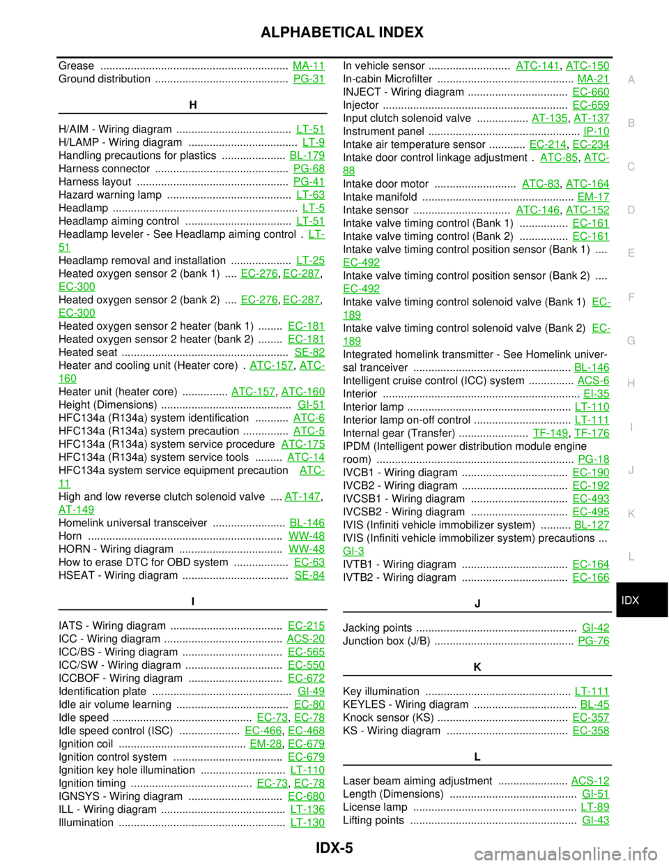
IDX-5
A
C
D
E
F
G
H
I
J
K
L B
IDX
ALPHABETICAL INDEX
Grease .............................................................. MA-11
Ground distribution ............................................ PG-31
H
H/AIM - Wiring diagram ...................................... LT-51
H/LAMP - Wiring diagram .................................... LT-9
Handling precautions for plastics ..................... BL-179
Harness connector ............................................ PG-68
Harness layout .................................................. PG-41
Hazard warning lamp ......................................... LT-63
Headlamp ............................................................. LT-5
Headlamp aiming control ................................... LT-51
Headlamp leveler - See Headlamp aiming control . LT-
51
Headlamp removal and installation .................... LT-25
Heated oxygen sensor 2 (bank 1) .... EC-276, EC-287,
EC-300
Heated oxygen sensor 2 (bank 2) .... EC-276, EC-287,
EC-300
Heated oxygen sensor 2 heater (bank 1) ........ EC-181
Heated oxygen sensor 2 heater (bank 2) ........ EC-181
Heated seat ....................................................... SE-82
Heater and cooling unit (Heater core) . ATC-157, ATC-
160
Heater unit (heater core) ............... ATC-157, ATC-160
Height (Dimensions) ........................................... GI-51
HFC134a (R134a) system identification ........... ATC-6
HFC134a (R134a) system precaution ............... ATC-5
HFC134a (R134a) system service procedure ATC-175
HFC134a (R134a) system service tools ......... ATC-14
HFC134a system service equipment precaution ATC-
11
High and low reverse clutch solenoid valve .... AT-147,
AT-149
Homelink universal transceiver ........................ BL-146
Horn ................................................................ WW-48
HORN - Wiring diagram .................................. WW-48
How to erase DTC for OBD system .................. EC-63
HSEAT - Wiring diagram ................................... SE-84
I
IATS - Wiring diagram ..................................... EC-215
ICC - Wiring diagram ....................................... ACS-20
ICC/BS - Wiring diagram ................................. EC-565
ICC/SW - Wiring diagram ................................ EC-550
ICCBOF - Wiring diagram ............................... EC-672
Identification plate .............................................. GI-49
Idle air volume learning ..................................... EC-80
Idle speed .............................................. EC-73, EC-78
Idle speed control (ISC) .................... EC-466, EC-468
Ignition coil .......................................... EM-28, EC-679
Ignition control system .................................... EC-679
Ignition key hole illumination ............................ LT-110
Ignition timing ........................................ EC-73, EC-78
IGNSYS - Wiring diagram ............................... EC-680
ILL - Wiring diagram ......................................... LT-136
Illumination ....................................................... LT-130
In vehicle sensor ........................... ATC-141, ATC-150
In-cabin Microfilter ............................................. MA-21
INJECT - Wiring diagram ................................. EC-660
Injector ............................................................. EC-659
Input clutch solenoid valve ................. AT-135, AT-137
Instrument panel .................................................. IP-10
Intake air temperature sensor ............ EC-214, EC-234
Intake door control linkage adjustment . ATC-85, ATC-
88
Intake door motor ........................... ATC-83, ATC-164
Intake manifold .................................................. EM-17
Intake sensor ................................ ATC-146, ATC-152
Intake valve timing control (Bank 1) ................ EC-161
Intake valve timing control (Bank 2) ................ EC-161
Intake valve timing control position sensor (Bank 1) ....
EC-492
Intake valve timing control position sensor (Bank 2) ....
EC-492
Intake valve timing control solenoid valve (Bank 1) EC-
189
Intake valve timing control solenoid valve (Bank 2) EC-
189
Integrated homelink transmitter - See Homelink univer-
sal tranceiver .................................................... BL-146
Intelligent cruise control (ICC) system ............... ACS-6
Interior ................................................................. EI-35
Interior lamp ...................................................... LT-110
Interior lamp on-off control ................................ LT-111
Internal gear (Transfer) ....................... TF-149, TF-176
IPDM (Intelligent power distribution module engine
room) ................................................................. PG-18
IVCB1 - Wiring diagram ................................... EC-190
IVCB2 - Wiring diagram ................................... EC-192
IVCSB1 - Wiring diagram ................................ EC-493
IVCSB2 - Wiring diagram ................................ EC-495
IVIS (Infiniti vehicle immobilizer system) .......... BL-127
IVIS (Infiniti vehicle immobilizer system) precautions ...
GI-3
IVTB1 - Wiring diagram ................................... EC-164
IVTB2 - Wiring diagram ................................... EC-166
J
Jacking points ..................................................... GI-42
Junction box (J/B) .............................................. PG-76
K
Key illumination ................................................ LT-111
KEYLES - Wiring diagram .................................. BL-45
Knock sensor (KS) ........................................... EC-357
KS - Wiring diagram ........................................ EC-358
L
Laser beam aiming adjustment ....................... ACS-12
Length (Dimensions) .......................................... GI-51
License lamp ...................................................... LT-89
Lifting points ....................................................... GI-43
Page 2112 of 3061
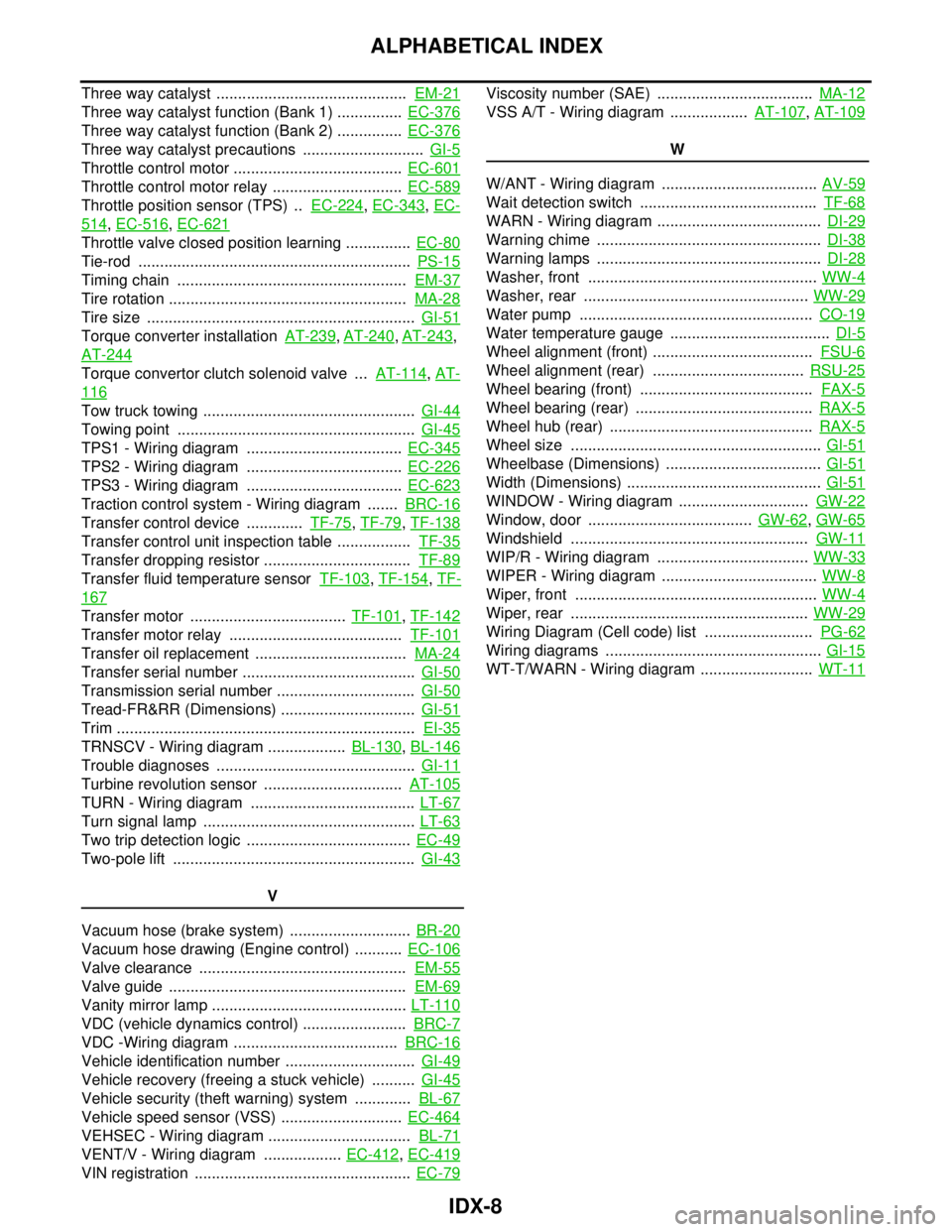
IDX-8
ALPHABETICAL INDEX
Three way catalyst ............................................ EM-21
Three way catalyst function (Bank 1) ............... EC-376
Three way catalyst function (Bank 2) ............... EC-376
Three way catalyst precautions ............................ GI-5
Throttle control motor ....................................... EC-601
Throttle control motor relay .............................. EC-589
Throttle position sensor (TPS) .. EC-224, EC-343, EC-
514, EC-516, EC-621
Throttle valve closed position learning ............... EC-80
Tie-rod ............................................................... PS-15
Timing chain ..................................................... EM-37
Tire rotation ....................................................... MA-28
Tire size .............................................................. GI-51
Torque converter installation AT-239, AT-240, AT-243,
AT-244
Torque convertor clutch solenoid valve ... AT-114, AT-
116
Tow truck towing ................................................. GI-44
Towing point ....................................................... GI-45
TPS1 - Wiring diagram .................................... EC-345
TPS2 - Wiring diagram .................................... EC-226
TPS3 - Wiring diagram .................................... EC-623
Traction control system - Wiring diagram ....... BRC-16
Transfer control device ............. TF-75, TF-79, TF-138
Transfer control unit inspection table ................. TF-35
Transfer dropping resistor .................................. TF-89
Transfer fluid temperature sensor TF-103, TF-154, TF-
167
Transfer motor .................................... TF-101, TF-142
Transfer motor relay ........................................ TF-101
Transfer oil replacement ................................... MA-24
Transfer serial number ........................................ GI-50
Transmission serial number ................................ GI-50
Tread-FR&RR (Dimensions) ............................... GI-51
Trim ..................................................................... EI-35
TRNSCV - Wiring diagram .................. BL-130, BL-146
Trouble diagnoses .............................................. GI-11
Turbine revolution sensor ................................ AT-105
TURN - Wiring diagram ...................................... LT-67
Turn signal lamp ................................................. LT-63
Two trip detection logic ...................................... EC-49
Two-pole lift ........................................................ GI-43
V
Vacuum hose (brake system) ............................ BR-20
Vacuum hose drawing (Engine control) ........... EC-106
Valve clearance ................................................ EM-55
Valve guide ....................................................... EM-69
Vanity mirror lamp ............................................. LT-110
VDC (vehicle dynamics control) ........................ BRC-7
VDC -Wiring diagram ...................................... BRC-16
Vehicle identification number .............................. GI-49
Vehicle recovery (freeing a stuck vehicle) .......... GI-45
Vehicle security (theft warning) system ............. BL-67
Vehicle speed sensor (VSS) ............................ EC-464
VEHSEC - Wiring diagram ................................. BL-71
VENT/V - Wiring diagram .................. EC-412, EC-419
VIN registration .................................................. EC-79
Viscosity number (SAE) .................................... MA-12
VSS A/T - Wiring diagram .................. AT-107, AT-109
W
W/ANT - Wiring diagram .................................... AV-59
Wait detection switch ......................................... TF-68
WARN - Wiring diagram ...................................... DI-29
Warning chime .................................................... DI-38
Warning lamps .................................................... DI-28
Washer, front ..................................................... WW-4
Washer, rear .................................................... WW-29
Water pump ...................................................... CO-19
Water temperature gauge ..................................... DI-5
Wheel alignment (front) ..................................... FSU-6
Wheel alignment (rear) ................................... RSU-25
Wheel bearing (front) ........................................ FAX-5
Wheel bearing (rear) ......................................... RAX-5
Wheel hub (rear) ............................................... RAX-5
Wheel size .......................................................... GI-51
Wheelbase (Dimensions) .................................... GI-51
Width (Dimensions) ............................................. GI-51
WINDOW - Wiring diagram .............................. GW-22
Window, door ...................................... GW-62, GW-65
Windshield ....................................................... GW-11
WIP/R - Wiring diagram ................................... WW-33
WIPER - Wiring diagram .................................... WW-8
Wiper, front ........................................................ WW-4
Wiper, rear ....................................................... WW-29
Wiring Diagram (Cell code) list ......................... PG-62
Wiring diagrams .................................................. GI-15
WT-T/WARN - Wiring diagram .......................... WT-11
Page 2354 of 3061
ENGINE OIL
LU-9
< SERVICE INFORMATION >
C
D
E
F
G
H
I
J
K
L
MA
LU
N
P O
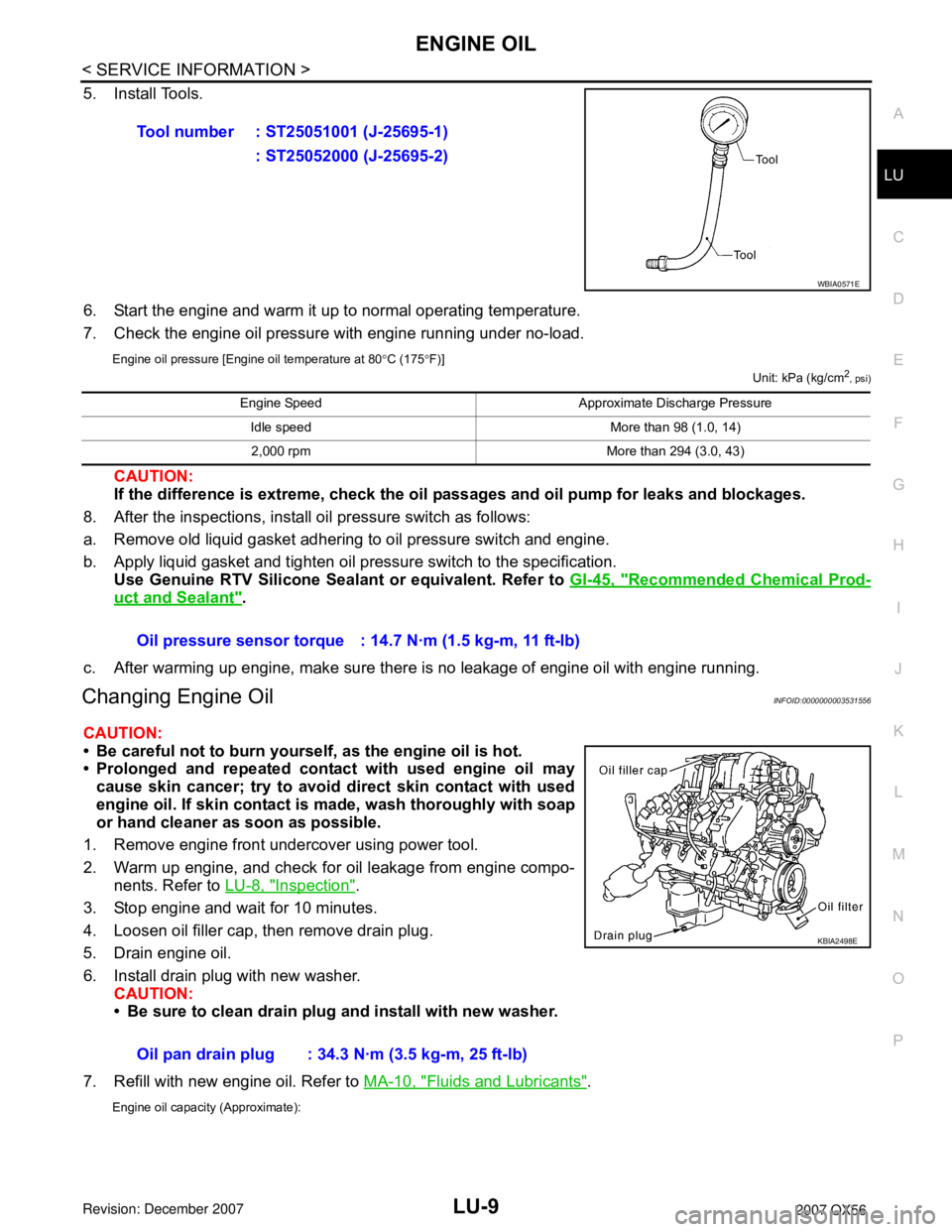
5. Install Tools.
6. Start the engine and warm it up to normal operating temperature.
7. Check the engine oil pressure with engine running under no-load.
Engine oil pressure [Engine oil temperature at 80°C (175°F)]
Unit: kPa (kg/cm2
, psi)
CAUTION:
If the difference is extreme, check the oil passages and oil pump for leaks and blockages.
8. After the inspections, install oil pressure switch as follows:
a. Remove old liquid gasket adhering to oil pressure switch and engine.
b. Apply liquid gasket and tighten oil pressure switch to the specification.
Use Genuine RTV Silicone Sealant or equivalent. Refer to GI-45, "
Recommended Chemical Prod-
uct and Sealant".
c. After warming up engine, make sure there is no leakage of engine oil with engine running.
Changing Engine OilINFOID:0000000003531556
CAUTION:
• Be careful not to burn yourself, as the engine oil is hot.
• Prolonged and repeated contact with used engine oil may
cause skin cancer; try to avoid direct skin contact with used
engine oil. If skin contact is made, wash thoroughly with soap
or hand cleaner as soon as possible.
1. Remove engine front undercover using power tool.
2. Warm up engine, and check for oil leakage from engine compo-
nents. Refer to LU-8, "
Inspection".
3. Stop engine and wait for 10 minutes.
4. Loosen oil filler cap, then remove drain plug.
5. Drain engine oil.
6. Install drain plug with new washer.
CAUTION:
• Be sure to clean drain plug and install with new washer.
7. Refill with new engine oil. Refer to MA-10, "
Fluids and Lubricants".
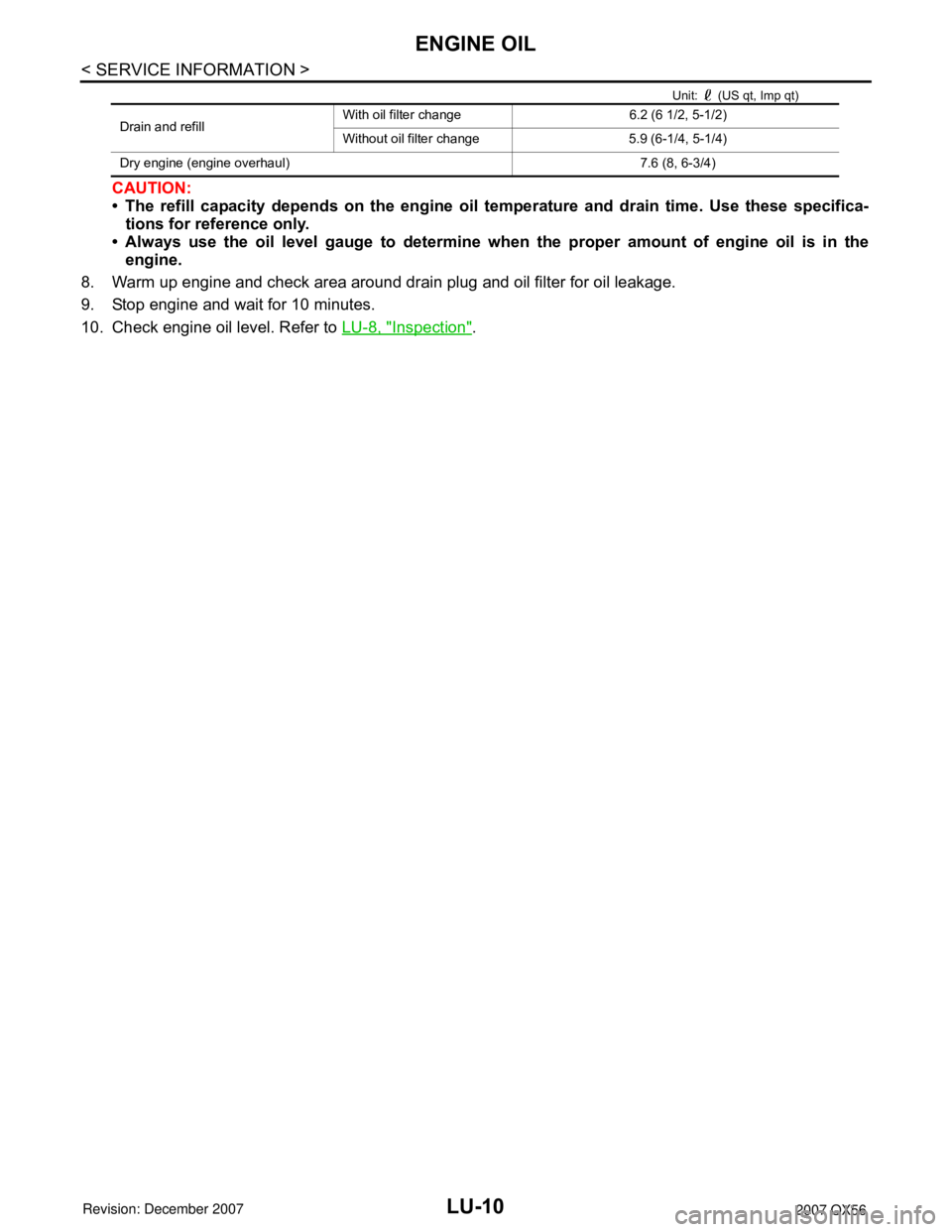
Engine oil capacity (Approximate):
Tool number : ST25051001 (J-25695-1)
: ST25052000 (J-25695-2)
WBIA0571E
Engine Speed Approximate Discharge Pressure
Idle speed More than 98 (1.0, 14)
2,000 rpm More than 294 (3.0, 43)
Oil pressure sensor torque : 14.7 N·m (1.5 kg-m, 11 ft-lb)
Oil pan drain plug : 34.3 N·m (3.5 kg-m, 25 ft-lb)
KBIA2498E
Page 2355 of 3061
LU-10
< SERVICE INFORMATION >
ENGINE OIL
Unit: (US qt, Imp qt)
CAUTION:
• The refill capacity depends on the engine oil temperature and drain time. Use these specifica-
tions for reference only.
• Always use the oil level gauge to determine when the proper amount of engine oil is in the
engine.
8. Warm up engine and check area around drain plug and oil filter for oil leakage.
9. Stop engine and wait for 10 minutes.
10. Check engine oil level. Refer to LU-8, "
Inspection".
Drain and refillWith oil filter change 6.2 (6 1/2, 5-1/2)
Without oil filter change 5.9 (6-1/4, 5-1/4)
Dry engine (engine overhaul) 7.6 (8, 6-3/4)
Page 2367 of 3061
GENERAL MAINTENANCE
MA-5
< SERVICE INFORMATION >
C
D
E
F
G
H
I
J
K
MA
B
MA
N
O
P
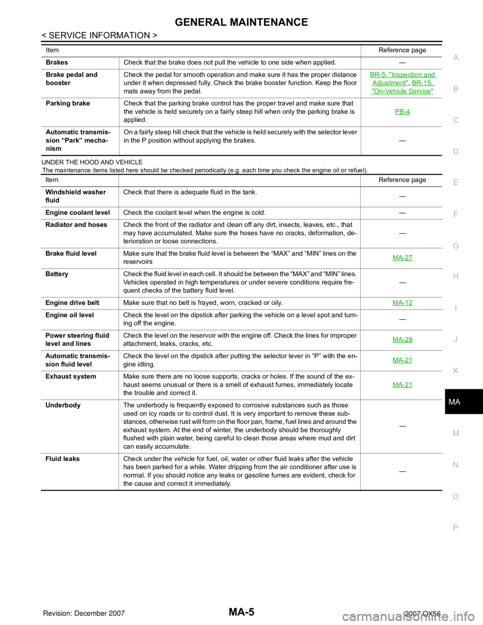
UNDER THE HOOD AND VEHICLE
The maintenance items listed here should be checked periodically (e.g. each time you check the engine oil or refuel).
BrakesCheck that the brake does not pull the vehicle to one side when applied. —
Brake pedal and
boosterCheck the pedal for smooth operation and make sure it has the proper distance
under it when depressed fully. Check the brake booster function. Keep the floor
mats away from the pedal.BR-5, "
Inspection and
Adjustment", BR-15,
"On-Vehicle Service"
Parking brakeCheck that the parking brake control has the proper travel and make sure that
the vehicle is held securely on a fairly steep hill when only the parking brake is
applied.PB-4
Automatic transmis-
sion “Park” mecha-
nismOn a fairly steep hill check that the vehicle is held securely with the selector lever
in the P position without applying the brakes. — ItemReference page
ItemReference page
Windshield washer
fluidCheck that there is adequate fluid in the tank.
—
Engine coolant levelCheck the coolant level when the engine is cold. —
Radiator and hosesCheck the front of the radiator and clean off any dirt, insects, leaves, etc., that
may have accumulated. Make sure the hoses have no cracks, deformation, de-
terioration or loose connections.—
Brake fluid levelMake sure that the brake fluid level is between the “MAX” and “MIN” lines on the
reservoirsMA-27
BatteryCheck the fluid level in each cell. It should be between the “MAX” and “MIN” lines.
Vehicles operated in high temperatures or under severe conditions require fre-
quent checks of the battery fluid level.—
Engine drive beltMake sure that no belt is frayed, worn, cracked or oily.MA-12
Engine oil levelCheck the level on the dipstick after parking the vehicle on a level spot and turn-
ing off the engine.—
Power steering fluid
level and linesCheck the level on the reservoir with the engine off. Check the lines for improper
attachment, leaks, cracks, etc.MA-28
Automatic transmis-
sion fluid levelCheck the level on the dipstick after putting the selector lever in “P” with the en-
gine idling.MA-21
Exhaust systemMake sure there are no loose supports, cracks or holes. If the sound of the ex-
haust seems unusual or there is a smell of exhaust fumes, immediately locate
the trouble and correct it.MA-21
UnderbodyThe underbody is frequently exposed to corrosive substances such as those
used on icy roads or to control dust. It is very important to remove these sub-
stances, otherwise rust will form on the floor pan, frame, fuel lines and around the
exhaust system. At the end of winter, the underbody should be thoroughly
flushed with plain water, being careful to clean those areas where mud and dirt
can easily accumulate.—
Fluid leaksCheck under the vehicle for fuel, oil, water or other fluid leaks after the vehicle
has been parked for a while. Water dripping from the air conditioner after use is
normal. If you should notice any leaks or gasoline fumes are evident, check for
the cause and correct it immediately.—
Page 2368 of 3061
MA-6
< SERVICE INFORMATION >
PERIODIC MAINTENANCE
PERIODIC MAINTENANCE
Introduction of Periodic MaintenanceINFOID:0000000003533860
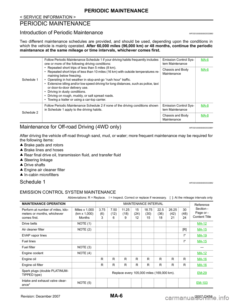
Two different maintenance schedules are provided, and should be used, depending upon the conditions in
which the vehicle is mainly operated. After 60,000 miles (96,000 km) or 48 months, continue the periodic
maintenance at the same mileage or time intervals, whichever comes first.
Maintenance for Off-road Driving (4WD only)INFOID:0000000003533861
After driving the vehicle off-road through sand, mud, or water; more frequent maintenance may be required for
the following items:
Brake pads and rotors
Brake lines and hoses
Rear final drive oil, transmission fluid, and transfer fluid
Steering linkage
Drive shafts
Engine air cleaner filter
In-cabin microfilters
Schedule 1INFOID:0000000003533862
EMISSION CONTROL SYSTEM MAINTENANCE
Abbreviations: R = Replace. I = Inspect. Correct or replace if necessary. [ ]: At the mileage intervals only
Schedule 1Follow Periodic Maintenance Schedule 1 if your driving habits frequently includes
one or more of the following driving conditions:
• Repeated short trips of less than 5 miles (8 km).
• Repeated short trips of less than 10 miles (16 km) with outside temperatures re-
maining below freezing.
• Operating in hot weather in stop-and-go “rush hour” traffic.
• Extensive idling and/or low speed driving for long distances, such as police, taxi
or door-to-door delivery use.
• Driving in dusty conditions.
• Driving on rough, muddy, or salt spread roads.
• Towing a trailer or using a car-top carrier.Emission Control Sys-
tem MaintenanceMA-6
Chassis and Body
MaintenanceMA-6
Schedule 2Follow Periodic Maintenance Schedule 2 if none of the driving conditions shown
in Schedule 1 apply to the driving habits.Emission Control Sys-
tem MaintenanceMA-8Chassis and Body
MaintenanceMA-8
MAINTENANCE OPERATIONMAINTENANCE INTERVAL
Reference
Section -
Page or -
Content Title Perform at number of miles, kilo-
meters or months, whichever
comes first.Miles x 1,000
(km x 1,000)
Months3.75
(6)
37.50
(12)
611 . 2 5
(18)
915
(24)
1218.75
(30)
1522.5
(36)
1826.25
(42)
2130
(48)
24
Drive belts NOTE (1)MA-12
Air cleaner filter NOTE (2) [R]MA-15
EVAP vapor linesI*MA-19
Fuel linesI*MA-15
Fuel filter NOTE (3)—
Engine coolant NOTE (4)MA-12
Engine oil R R R R R R R RMA-16
Engine oil filter R R R R R R R RMA-16
Spark plugs (double PLATINUM-
TIPPED type)Replace every 105,000 miles (169,000 km).EM-29
Intake and exhaust valve clear-
ance*NOTE (5)EM-103