2007 INFINITI QX56 oil temperature
[x] Cancel search: oil temperaturePage 1180 of 3061

TROUBLE DIAGNOSIS
EC-97
< SERVICE INFORMATION >
C
D
E
F
G
H
I
J
K
L
MA
EC
N
P O
13. Intake valve timing control position
sensor (bank 1) (view with engine
cover and intake air duct removed)14. Intake valve timing control solenoid
valve (bank 2) (view with engine cov-
er and intake air duct removed)15. Drive belt (view with engine cover
and intake air duct removed)
16. Radiator hose (view with engine cov-
er and intake air duct removed)17. Intake valve timing control solenoid
valve (bank 1) (view with engine cov-
er and intake air duct removed)
1. Knock sensor (bank 1) (view with en-
gine removed)2. Knock sensor (bank 2) (view with en-
gine removed)3. Battery current sensor
4. Power steering pressure sensor 5. Power steering fluid reservoir 6. Intake manifold
7. Engine coolant temperature sensor 8. Ignition coils (with power transistor) 9. Ignition coil (with power transistor)
10. Injector harness connectors (bank 2) 11. Injector harness connectors (bank 1)
BBIA0774E
Page 1203 of 3061

EC-120
< SERVICE INFORMATION >
TROUBLE DIAGNOSIS
*: Leaving cooling fan OFF with CONSULT-II while engine is running may cause the engine to overheat.
DTC & SRT CONFIRMATION MODE
SRT STATUS Mode
For details, refer to EC-49, "Emission-related Diagnostic Information".
SRT WORK SUPPORT Mode
This mode enables a technician to drive a vehicle to set the SRT while monitoring the SRT status.
DTC WORK SUPPORT Mode
TEST ITEM CONDITION JUDGEMENT CHECK ITEM (REMEDY)
FUEL INJEC-
TION• Engine: Return to the original
trouble condition
• Change the amount of fuel injec-
tion using CONSULT-II.If trouble symptom disappears, see
CHECK ITEM.• Harness and connectors
• Fuel injector
• Air fuel ratio (A/F) sensor 1
IGNITION TIM-
ING• Engine: Return to the original
trouble condition
• Timing light: Set
• Retard the ignition timing using
CONSULT-II.If trouble symptom disappears, see
CHECK ITEM.• Perform Idle Air Volume Learning.
POWER BAL-
ANCE• Engine: After warming up, idle the
engine.
• A/C switch: OFF
• Selector lever: P or N
• Cut off each injector signal one at
a time using CONSULT-II.Engine runs rough or dies.• Harness and connectors
• Compression
• Fuel injector
• Power transistor
•Spark plug
• Ignition coil
COOLING FAN*• Ignition switch: ON
• Turn the cooling fan HI and OFF
using CONSULT-II.Cooling fan moves and stops.• Harness and connectors
• Cooling fan motor
• IPDM E/R
ENG COOLANT
TEMP• Engine: Return to the original
trouble condition
• Change the engine coolant tem-
perature using CONSULT-II.If trouble symptom disappears, see
CHECK ITEM.• Harness and connectors
• Engine coolant temperature sen-
sor
• Fuel injector
FUEL PUMP RE-
LAY• Ignition switch: ON
(Engine stopped)
• Turn the fuel pump relay ON and
OFF using CONSULT-II and lis-
ten to operating sound.Fuel pump relay makes the operat-
ing sound.• Harness and connectors
•Fuel pump relay
PURG VOL
CONT/V• Engine: After warming up, run en-
gine at 1,500 rpm.
• Change the EVAP canister purge
volume control solenoid valve
opening percent using CON-
SULT-II.Engine speed changes according to
the opening percent.• Harness and connectors
• Solenoid valve
FUEL/T TEMP
SEN• Change the fuel tank temperature using CONSULT-II.
VENT CON-
TROL/V• Ignition switch: ON
(Engine stopped)
• Turn solenoid valve ON and OFF
with the CONSULT-II and listen to
operating sound.Solenoid valve makes an operating
sound.• Harness and connectors
• Solenoid valve
V/T ASSIGN AN-
GLE• Engine: Return to the original
trouble condition
• Change intake valve timing using
CONSULT-II.If trouble symptom disappears, see
CHECK ITEM.• Harness and connectors
• Intake valve timing control sole-
noid valve
ALTERNATOR
DUTY•Engine: Idle
• Change duty ratio using CON-
SULT-II.Battery voltage changes.• Harness and connectors
• IPDM E/R
•Alternator
Page 1215 of 3061
EC-132
< SERVICE INFORMATION >
TROUBLE DIAGNOSIS - SPECIFICATION VALUE
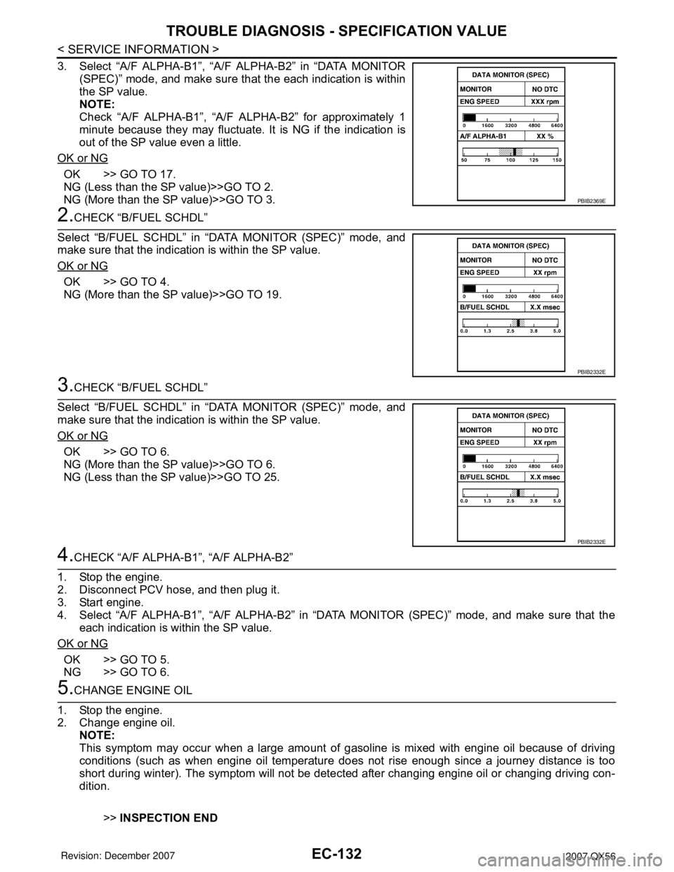
3. Select “A/F ALPHA-B1”, “A/F ALPHA-B2” in “DATA MONITOR
(SPEC)” mode, and make sure that the each indication is within
the SP value.
NOTE:
Check “A/F ALPHA-B1”, “A/F ALPHA-B2” for approximately 1
minute because they may fluctuate. It is NG if the indication is
out of the SP value even a little.
OK or NG
OK >> GO TO 17.
NG (Less than the SP value)>>GO TO 2.
NG (More than the SP value)>>GO TO 3.
2.CHECK “B/FUEL SCHDL”
Select “B/FUEL SCHDL” in “DATA MONITOR (SPEC)” mode, and
make sure that the indication is within the SP value.
OK or NG
OK >> GO TO 4.
NG (More than the SP value)>>GO TO 19.
3.CHECK “B/FUEL SCHDL”
Select “B/FUEL SCHDL” in “DATA MONITOR (SPEC)” mode, and
make sure that the indication is within the SP value.
OK or NG
OK >> GO TO 6.
NG (More than the SP value)>>GO TO 6.
NG (Less than the SP value)>>GO TO 25.
4.CHECK “A/F ALPHA-B1”, “A/F ALPHA-B2”
1. Stop the engine.
2. Disconnect PCV hose, and then plug it.
3. Start engine.
4. Select “A/F ALPHA-B1”, “A/F ALPHA-B2” in “DATA MONITOR (SPEC)” mode, and make sure that the
each indication is within the SP value.
OK or NG
OK >> GO TO 5.
NG >> GO TO 6.
5.CHANGE ENGINE OIL
1. Stop the engine.
2. Change engine oil.
NOTE:
This symptom may occur when a large amount of gasoline is mixed with engine oil because of driving
conditions (such as when engine oil temperature does not rise enough since a journey distance is too
short during winter). The symptom will not be detected after changing engine oil or changing driving con-
dition.
>>INSPECTION END
PBIB2369E
PBIB2332E
PBIB2332E
Page 1232 of 3061
DTC P0011, P0021 IVT CONTROL
EC-149
< SERVICE INFORMATION >
C
D
E
F
G
H
I
J
K
L
MA
EC
N
P O
DTC P0011, P0021 IVT CONTROL
DescriptionINFOID:0000000003531648
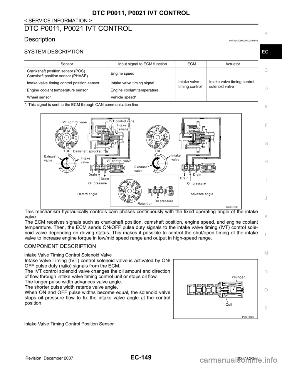
SYSTEM DESCRIPTION
*: This signal is sent to the ECM through CAN communication line
This mechanism hydraulically controls cam phases continuously with the fixed operating angle of the intake
valve.
The ECM receives signals such as crankshaft position, camshaft position, engine speed, and engine coolant
temperature. Then, the ECM sends ON/OFF pulse duty signals to the intake valve timing (IVT) control sole-
noid valve depending on driving status. This makes it possible to control the shut/open timing of the intake
valve to increase engine torque in low/mid speed range and output in high-speed range.
COMPONENT DESCRIPTION
Intake Valve Timing Control Solenoid Valve
Intake Valve Timing (IVT) control solenoid valve is activated by ON/
OFF pulse duty (ratio) signals from the ECM.
The IVT control solenoid valve changes the oil amount and direction
of flow through intake valve timing control unit or stops oil flow.
The longer pulse width advances valve angle.
The shorter pulse width retards valve angle.
When ON and OFF pulse widths become equal, the solenoid valve
stops oil pressure flow to fix the intake valve angle at the control
position.
Intake Valve Timing Control Position Sensor
Sensor Input signal to ECM function ECM Actuator
Crankshaft position sensor (POS)
Camshaft position sensor (PHASE)Engine speed
Intake valve
timing controlIntake valve timing control
solenoid valve Intake valve timing control position sensor Intake valve timing signal
Engine coolant temperature sensor Engine coolant temperature
Wheel sensor Vehicle speed*
PBIB3276E
PBIB1842E
Page 1553 of 3061
EC-470
< SERVICE INFORMATION >
DTC P1217 ENGINE OVER TEMPERATURE
On Board Diagnosis Logic
INFOID:0000000003531991
If the cooling fan or another component in the cooling system malfunctions, engine coolant temperature will
rise.
When the engine coolant temperature reaches an abnormally high temperature condition, a malfunction is
indicated.
This self-diagnosis has the one trip detection logic.
CAUTION:
When a malfunction is indicated, be sure to replace the coolant. Refer to CO-9, "
Changing Engine
Coolant". Also, replace the engine oil. Refer to LU-9, "Changing Engine Oil".
1. Fill radiator with coolant up to specified level with a filling speed of 2 liters per minute. Be sure to
use coolant with the proper mixture ratio. Refer to MA-10, "
SAE Viscosity Number".
2. After refilling coolant, run engine to ensure that no water-flow noise is emitted.
Overall Function CheckINFOID:0000000003531992
Use this procedure to check the overall function of the cooling fan. During this check, a DTC might not be con-
firmed.
WARNING:
Never remove the radiator cap and/or reservoir tank cap when the engine is hot. Serious burns could
be caused by high pressure fluid escaping from the radiator and/or reservoir tank.
Wrap a thick cloth around cap. Carefully remove the cap by turning it a quarter turn to allow built-up
pressure to escape. Then turn the cap all the way off.
WITH CONSULT-II
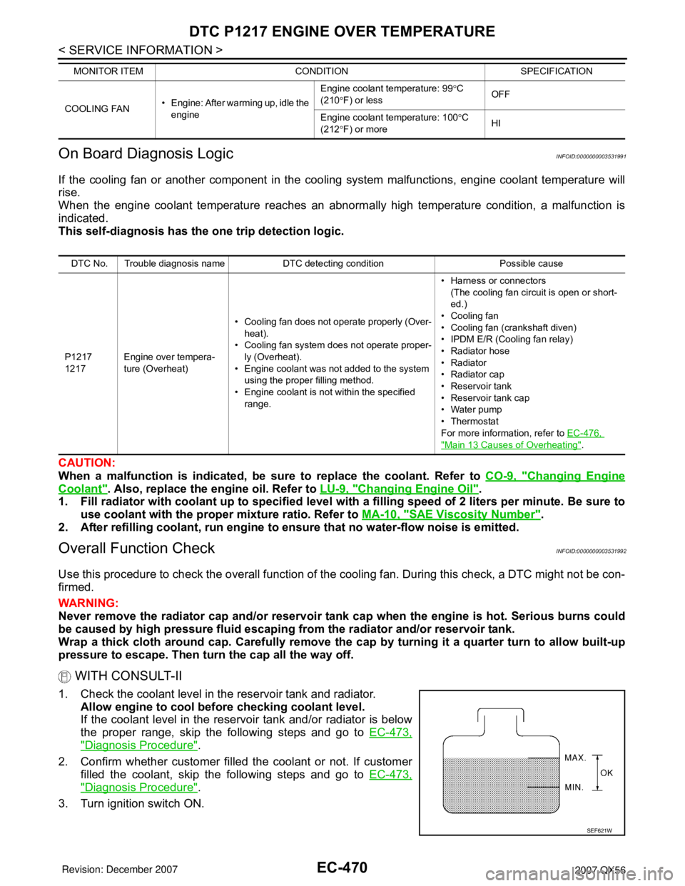
1. Check the coolant level in the reservoir tank and radiator.
Allow engine to cool before checking coolant level.
If the coolant level in the reservoir tank and/or radiator is below
the proper range, skip the following steps and go to EC-473,
"Diagnosis Procedure".
2. Confirm whether customer filled the coolant or not. If customer
filled the coolant, skip the following steps and go to EC-473,
"Diagnosis Procedure".
3. Turn ignition switch ON.
COOLING FAN• Engine: After warming up, idle the
engineEngine coolant temperature: 99°C
(210°F) or lessOFF
Engine coolant temperature: 100°C
(212°F) or moreHI MONITOR ITEM CONDITION SPECIFICATION
DTC No. Trouble diagnosis name DTC detecting condition Possible cause
P1217
1217Engine over tempera-
ture (Overheat)• Cooling fan does not operate properly (Over-
heat).
• Cooling fan system does not operate proper-
ly (Overheat).
• Engine coolant was not added to the system
using the proper filling method.
• Engine coolant is not within the specified
range.• Harness or connectors
(The cooling fan circuit is open or short-
ed.)
• Cooling fan
• Cooling fan (crankshaft diven)
• IPDM E/R (Cooling fan relay)
•Radiator hose
•Radiator
•Radiator cap
• Reservoir tank
• Reservoir tank cap
• Water pump
•Thermostat
For more information, refer to EC-476,
"Main 13 Causes of Overheating".
SEF621W
Page 1835 of 3061
CYLINDER HEADEM-65
< SERVICE INFORMATION >
C
DE
F
G H
I
J
K L
M A
EM
NP
O
Removal and InstallationINFOID:0000000003531541
REMOVAL
1. Remove the engine assembly from the vehicle. Refer to
EM-74, "Removal and Installation".
2. Remove the following components and related parts: • Drive belt auto tensioner drive belts and idler pulley. Refer to EM-13, "
Removal and Installation".
• Thermostat housing and hose. Refer to CO-20, "
Removal and Installation".
• Oil pan and oil strainer. Refer to EM-24, "
Removal and Installation".
• Fuel tube and fuel injector assembly. Refer to EM-31, "
Removal and Installation".
• Intake manifold. Refer to EM-17, "
Removal and Installation".
• Ignition coil. Refer to EM-28, "
Removal and Installation".
• Rocker cover. Refer to EM-35, "
Removal and Installation".
3. Remove the crankshaft pulley, front cover, oil pump, and timing chain. Refer to EM-38, "
Removal and
Installation".
4. Remove the camshaft sprockets and camshafts. Refer to EM-46, "
Removal and Installation".
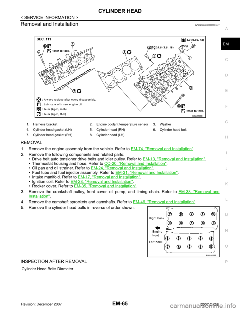
5. Remove the cylinder head bolts in reverse of order shown.
INSPECTION AFTER REMOVAL
Cylinder Head Bolts Diameter
1. Harness bracket 2. Engine coolant temperature sensor 3. Washer
4. Cylinder head gasket (LH) 5. Cylinder head (RH) 6. Cylinder head bolt
7. Cylinder head gasket (RH) 8. Cylinder head (LH)
KBIA2528E
PBIC0068E
Page 1970 of 3061
GI-4
< SERVICE INFORMATION >
PRECAUTIONS
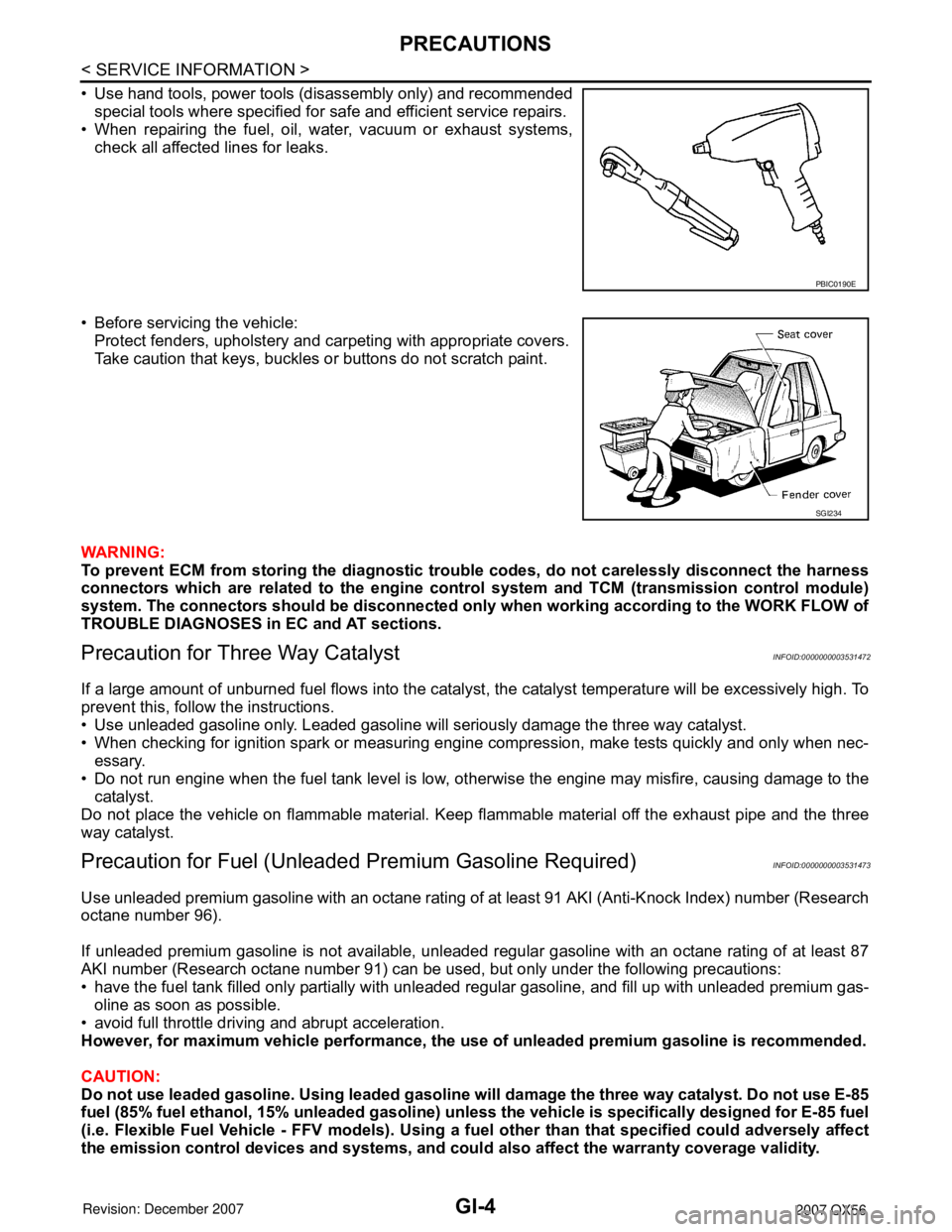
• Use hand tools, power tools (disassembly only) and recommended
special tools where specified for safe and efficient service repairs.
• When repairing the fuel, oil, water, vacuum or exhaust systems,
check all affected lines for leaks.
• Before servicing the vehicle:
Protect fenders, upholstery and carpeting with appropriate covers.
Take caution that keys, buckles or buttons do not scratch paint.
WARNING:
To prevent ECM from storing the diagnostic trouble codes, do not carelessly disconnect the harness
connectors which are related to the engine control system and TCM (transmission control module)
system. The connectors should be disconnected only when working according to the WORK FLOW of
TROUBLE DIAGNOSES in EC and AT sections.
Precaution for Three Way CatalystINFOID:0000000003531472
If a large amount of unburned fuel flows into the catalyst, the catalyst temperature will be excessively high. To
prevent this, follow the instructions.
• Use unleaded gasoline only. Leaded gasoline will seriously damage the three way catalyst.
• When checking for ignition spark or measuring engine compression, make tests quickly and only when nec-
essary.
• Do not run engine when the fuel tank level is low, otherwise the engine may misfire, causing damage to the
catalyst.
Do not place the vehicle on flammable material. Keep flammable material off the exhaust pipe and the three
way catalyst.
Precaution for Fuel (Unleaded Premium Gasoline Required)INFOID:0000000003531473
Use unleaded premium gasoline with an octane rating of at least 91 AKI (Anti-Knock Index) number (Research
octane number 96).
If unleaded premium gasoline is not available, unleaded regular gasoline with an octane rating of at least 87
AKI number (Research octane number 91) can be used, but only under the following precautions:
• have the fuel tank filled only partially with unleaded regular gasoline, and fill up with unleaded premium gas-
oline as soon as possible.
• avoid full throttle driving and abrupt acceleration.
However, for maximum vehicle performance, the use of unleaded premium gasoline is recommended.
CAUTION:
Do not use leaded gasoline. Using leaded gasoline will damage the three way catalyst. Do not use E-85
fuel (85% fuel ethanol, 15% unleaded gasoline) unless the vehicle is specifically designed for E-85 fuel
(i.e. Flexible Fuel Vehicle - FFV models). Using a fuel other than that specified could adversely affect
the emission control devices and systems, and could also affect the warranty coverage validity.
PBIC0190E
SGI234
Page 1999 of 3061
SERVICE INFORMATION FOR ELECTRICAL INCIDENT
GI-33
< SERVICE INFORMATION >
C
D
E
F
G
H
I
J
K
L
MB
GI
N
O
P
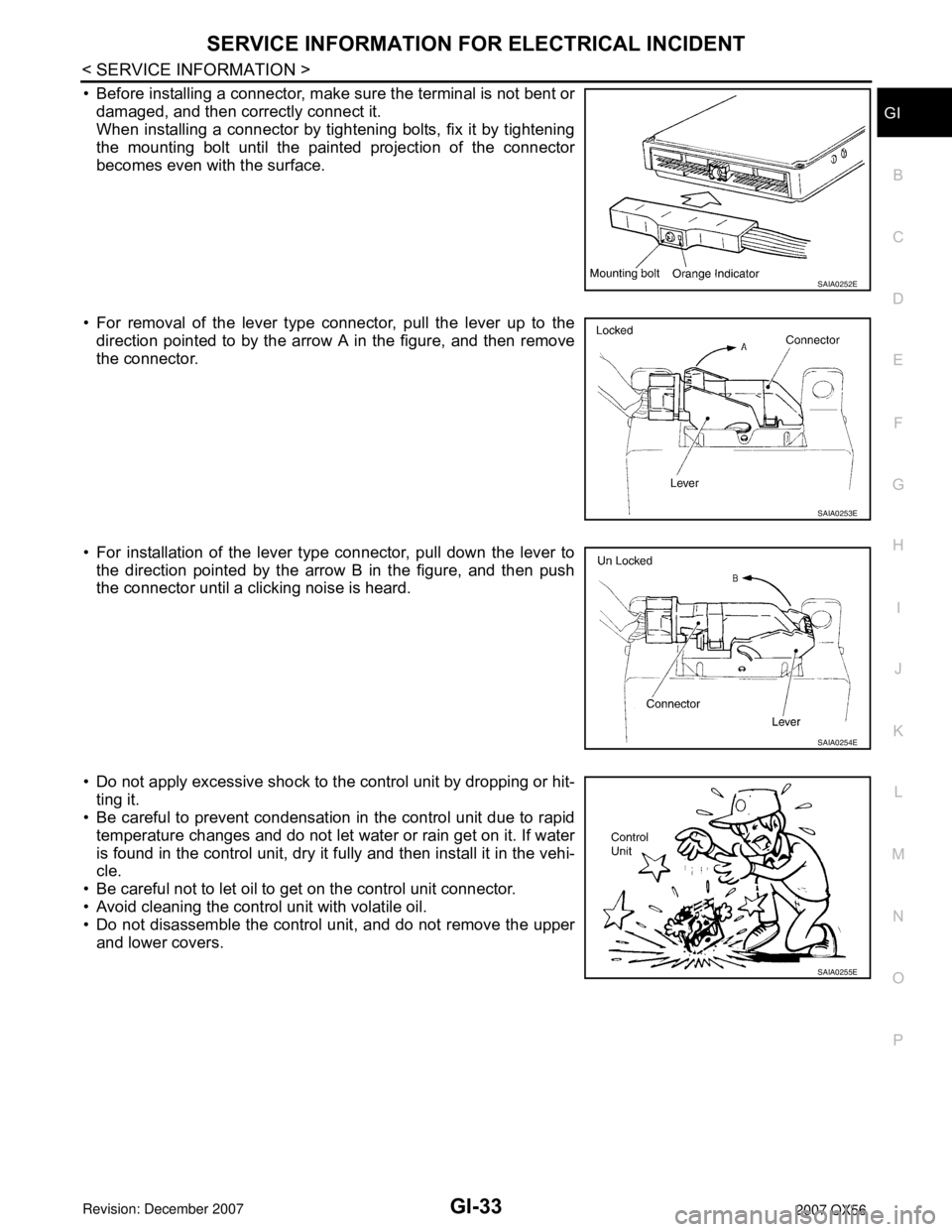
• Before installing a connector, make sure the terminal is not bent or
damaged, and then correctly connect it.
When installing a connector by tightening bolts, fix it by tightening
the mounting bolt until the painted projection of the connector
becomes even with the surface.
• For removal of the lever type connector, pull the lever up to the
direction pointed to by the arrow A in the figure, and then remove
the connector.
• For installation of the lever type connector, pull down the lever to
the direction pointed by the arrow B in the figure, and then push
the connector until a clicking noise is heard.
• Do not apply excessive shock to the control unit by dropping or hit-
ting it.
• Be careful to prevent condensation in the control unit due to rapid
temperature changes and do not let water or rain get on it. If water
is found in the control unit, dry it fully and then install it in the vehi-
cle.
• Be careful not to let oil to get on the control unit connector.
• Avoid cleaning the control unit with volatile oil.
• Do not disassemble the control unit, and do not remove the upper
and lower covers.
SAIA0252E
SAIA0253E
SAIA0254E
SAIA0255E