2007 INFINITI QX56 engine
[x] Cancel search: enginePage 2252 of 3061

HEADLAMP AIMING CONTROL
LT-45
< SERVICE INFORMATION >
C
D
E
F
G
H
I
J
L
MA
B
LT
N
O
P
HEADLAMP AIMING CONTROL
System DescriptionINFOID:0000000003533384
The headlamp aiming system is controlled by the headlamp aiming switch.
Power is supplied at all times
• to ignition relay, located in the IPDM E/R (intelligent power distribution module engine room), and
• through 50A fusible link (letter f , located in the fuse and fusible link box)
• to BCM (body control module) terminal 70, and
• to headlamp low relay, located in the IPDM E/R (intelligent power distribution module engine room), and
• through 20A fuse (No. 53, located in the IPDM E/R)
• to CPU (central processing unit) of the IPDM E/R.
With the ignition switch in the ON or START position, power is supplied
• to ignition relay, located in the IPDM E/R, and
• through 10A fuse (No. 59, located in the fuse and relay box)
• to BCM terminal 38.
When the ignition switch is in the ACC or ON position, power is supplied
• through 10A fuse [No. 4, located in the fuse block (J/B)]
• to BCM terminal 11.
When the lighting switch is in the 2ND position or AUTO position (auto lights ON), the headlamp low relay
(located in the IPDM E/R) is energized. When energized, power is supplied
• through 15A fuse (No. 41, located in the IPDM E/R)
• through IPDM E/R terminal 26
• to front combination lamp LH and RH (headlamp aiming motor) terminal 8.
Ground is supplied
• to front combination lamp LH and RH (headlamp aiming motor) terminal 4
• through grounds E9, E15 and E24, and
• to front combination lamp LH and RH (headlamp aiming motor) terminal 7
• through headlamp aiming switch terminal 1
• through headlamp aiming switch terminal 2
• through grounds M57, M61 and M79.
With power and ground supplied, headlamp aiming motors operate according to the aiming switch position.
Page 2256 of 3061
FRONT FOG LAMP
LT-49
< SERVICE INFORMATION >
C
D
E
F
G
H
I
J
L
MA
B
LT
N
O
P
FRONT FOG LAMP
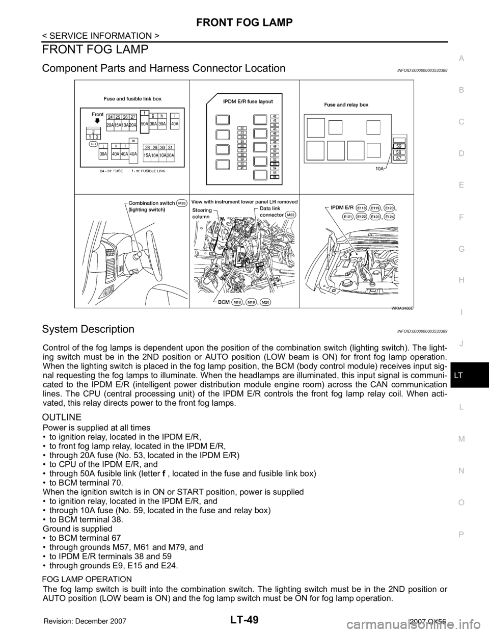
Component Parts and Harness Connector LocationINFOID:0000000003533388
System DescriptionINFOID:0000000003533389
Control of the fog lamps is dependent upon the position of the combination switch (lighting switch). The light-
ing switch must be in the 2ND position or AUTO position (LOW beam is ON) for front fog lamp operation.
When the lighting switch is placed in the fog lamp position, the BCM (body control module) receives input sig-
nal requesting the fog lamps to illuminate. When the headlamps are illuminated, this input signal is communi-
cated to the IPDM E/R (intelligent power distribution module engine room) across the CAN communication
lines. The CPU (central processing unit) of the IPDM E/R controls the front fog lamp relay coil. When acti-
vated, this relay directs power to the front fog lamps.
OUTLINE
Power is supplied at all times
• to ignition relay, located in the IPDM E/R,
• to front fog lamp relay, located in the IPDM E/R,
• through 20A fuse (No. 53, located in the IPDM E/R)
• to CPU of the IPDM E/R, and
• through 50A fusible link (letter f , located in the fuse and fusible link box)
• to BCM terminal 70.
When the ignition switch is in ON or START position, power is supplied
• to ignition relay, located in the IPDM E/R, and
• through 10A fuse (No. 59, located in the fuse and relay box)
• to BCM terminal 38.
Ground is supplied
• to BCM terminal 67
• through grounds M57, M61 and M79, and
• to IPDM E/R terminals 38 and 59
• through grounds E9, E15 and E24.
FOG LAMP OPERATION
The fog lamp switch is built into the combination switch. The lighting switch must be in the 2ND position or
AUTO position (LOW beam is ON) and the fog lamp switch must be ON for fog lamp operation.
WKIA3466E
Page 2262 of 3061
FRONT FOG LAMP
LT-55
< SERVICE INFORMATION >
C
D
E
F
G
H
I
J
L
MA
B
LT
N
O
P
Aiming AdjustmentINFOID:0000000003533400
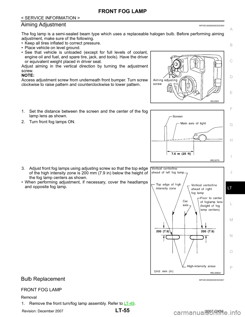
The fog lamp is a semi-sealed beam type which uses a replaceable halogen bulb. Before performing aiming
adjustment, make sure of the following.
• Keep all tires inflated to correct pressure.
• Place vehicle on level ground.
• See that vehicle is unloaded (except for full levels of coolant,
engine oil and fuel, and spare tire, jack, and tools). Have the driver
or equivalent weight placed in driver seat.
Adjust aiming in the vertical direction by turning the adjustment
screw.
NOTE:
Access adjustment screw from underneath front bumper. Turn screw
clockwise to raise pattern and counterclockwise to lower pattern.
1. Set the distance between the screen and the center of the fog
lamp lens as shown.
2. Turn front fog lamps ON.
3. Adjust front fog lamps using adjusting screw so that the top edge
of the high intensity zone is 200 mm (7.9 in) below the height of
the fog lamp centers as shown.
• When performing adjustment, if necessary, cover the headlamps
and opposite fog lamp.
Bulb ReplacementINFOID:0000000003533401
FRONT FOG LAMP
Removal
1. Remove the front turn/fog lamp assembly. Refer to LT- 4 9.
SEL350X
MEL327G
MEL328GA
Page 2289 of 3061
LT-82
< SERVICE INFORMATION >
PARKING, LICENSE PLATE AND TAIL LAMPS
PARKING, LICENSE PLATE AND TAIL LAMPS
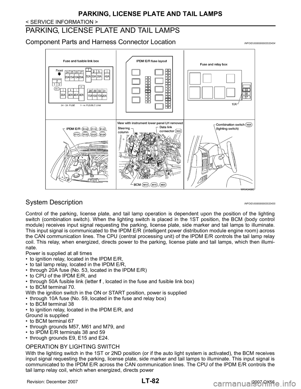
Component Parts and Harness Connector LocationINFOID:0000000003533434
System DescriptionINFOID:0000000003533435
Control of the parking, license plate, and tail lamp operation is dependent upon the position of the lighting
switch (combination switch). When the lighting switch is placed in the 1ST position, the BCM (body control
module) receives input signal requesting the parking, license plate, side marker and tail lamps to illuminate.
This input signal is communicated to the IPDM E/R (intelligent power distribution module engine room) across
the CAN communication lines. The CPU (central processing unit) of the IPDM E/R controls the tail lamp relay
coil. This relay, when energized, directs power to the parking, license plate and tail lamps, which then illumi-
nate.
Power is supplied at all times
• to ignition relay, located in the IPDM E/R,
• to tail lamp relay, located in the IPDM E/R,
• through 20A fuse (No. 53, located in the IPDM E/R)
• to CPU of the IPDM E/R, and
• through 50A fusible link (letter f , located in the fuse and fusible link box)
• to BCM terminal 70.
With the ignition switch in the ON or START position, power is supplied
• through 10A fuse (No. 59, located in the fuse and relay box)
• to BCM terminal 38
• to ignition relay, located in the IPDM E/R, and
Ground is supplied
• to BCM terminal 67
• through grounds M57, M61 and M79, and
• to IPDM E/R terminals 38 and 59
• through grounds E9, E15 and E24.
OPERATION BY LIGHTING SWITCH
With the lighting switch in the 1ST or 2ND position (or if the auto light system is activated), the BCM receives
input signal requesting the parking, license plate, side marker and tail lamps to illuminate. This input signal is
communicated to the IPDM E/R across the CAN communication lines. The CPU of the IPDM E/R controls the
tail lamp relay coil, which when energized, directs power
WKIA3468E
Page 2301 of 3061
LT-94
< SERVICE INFORMATION >
TRAILER TOW
TRAILER TOW
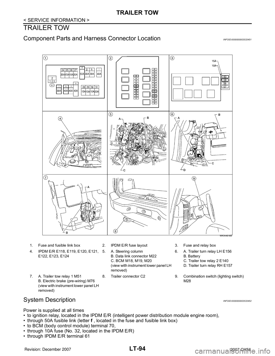
Component Parts and Harness Connector LocationINFOID:0000000003533451
System DescriptionINFOID:0000000003533452
Power is supplied at all times
• to ignition relay, located in the IPDM E/R (intelligent power distribution module engine room),
• through 50A fusible link (letter f , located in the fuse and fusible link box)
• to BCM (body control module) terminal 70,
• through 10A fuse (No. 32, located in the IPDM E/R)
• through IPDM E/R terminal 61
1. Fuse and fusible link box 2. IPDM E/R fuse layout 3. Fuse and relay box
4. IPDM E/R E118, E119, E120, E121,
E122, E123, E1245. A. Steering column
B. Data link connector M22
C. BCM M18, M19, M20
(view with instrument lower panel LH
removed)6. A. Trailer turn relay LH E156
B. Battery
C. Trailer tow relay 2 E140
D. Trailer turn relay RH E157
7. A. Trailer tow relay 1 M51
B. Electric brake (pre-wiring) M76
(view with instrument lower panel LH
removed)8. Trailer connector C2 9. Combination switch (lighting switch)
M28
WKIA4616E
Page 2327 of 3061
LT-120
< SERVICE INFORMATION >
ILLUMINATION
ILLUMINATION
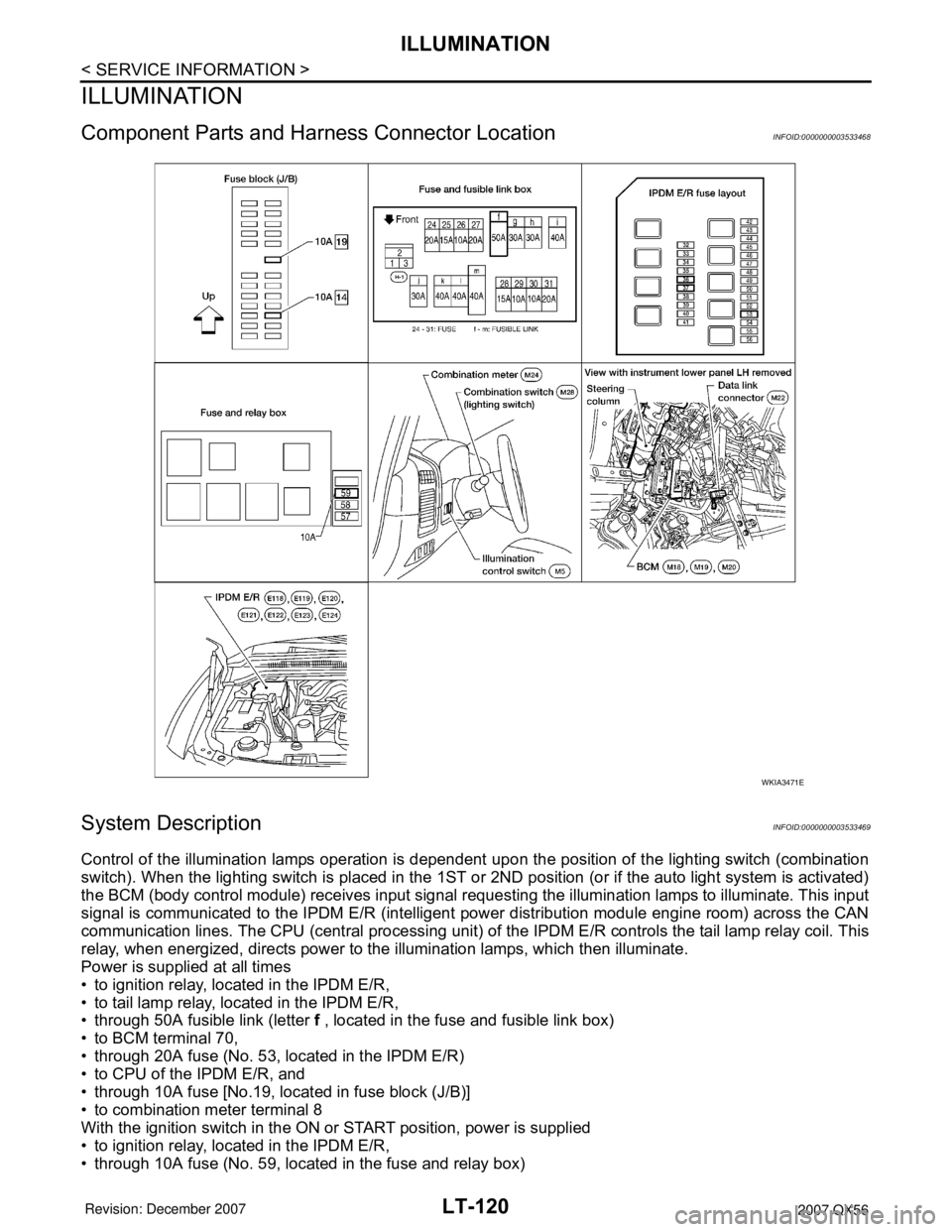
Component Parts and Harness Connector LocationINFOID:0000000003533468
System DescriptionINFOID:0000000003533469
Control of the illumination lamps operation is dependent upon the position of the lighting switch (combination
switch). When the lighting switch is placed in the 1ST or 2ND position (or if the auto light system is activated)
the BCM (body control module) receives input signal requesting the illumination lamps to illuminate. This input
signal is communicated to the IPDM E/R (intelligent power distribution module engine room) across the CAN
communication lines. The CPU (central processing unit) of the IPDM E/R controls the tail lamp relay coil. This
relay, when energized, directs power to the illumination lamps, which then illuminate.
Power is supplied at all times
• to ignition relay, located in the IPDM E/R,
• to tail lamp relay, located in the IPDM E/R,
• through 50A fusible link (letter f , located in the fuse and fusible link box)
• to BCM terminal 70,
• through 20A fuse (No. 53, located in the IPDM E/R)
• to CPU of the IPDM E/R, and
• through 10A fuse [No.19, located in fuse block (J/B)]
• to combination meter terminal 8
With the ignition switch in the ON or START position, power is supplied
• to ignition relay, located in the IPDM E/R,
• through 10A fuse (No. 59, located in the fuse and relay box)
WKIA3471E
Page 2346 of 3061

LU-1
ENGINE
C
D
E
F
G
H
I
J
K
L
M
SECTION LU
A
LU
N
O
P
CONTENTS
ENGINE LUBRICATION SYSTEM
SERVICE INFORMATION ............................2
PRECAUTIONS ...................................................2
Precaution for Supplemental Restraint System
(SRS) "AIR BAG" and "SEAT BELT PRE-TEN-
SIONER" ...................................................................
2
Precaution for Liquid Gasket .....................................2
PREPARATION ...................................................4
Special Service Tool .................................................4
Commercial Service Tool ..........................................4
LUBRICATION SYSTEM ....................................6
Lubrication Circuit .....................................................6
Schematic .................................................................7
ENGINE OIL ........................................................8
Inspection .................................................................8
Changing Engine Oil .................................................9
OIL FILTER .......................................................11
Removal and Installation .........................................11
OIL COOLER ....................................................12
Removal and Installation .........................................12
OIL PUMP .........................................................14
Removal and Installation .........................................14
Disassembly and Assembly .....................................15
SERVICE DATA AND SPECIFICATIONS
(SDS) .................................................................
17
Standard and Limit ..................................................17
Page 2348 of 3061
PRECAUTIONS
LU-3
< SERVICE INFORMATION >
C
D
E
F
G
H
I
J
K
L
MA
LU
N
P O
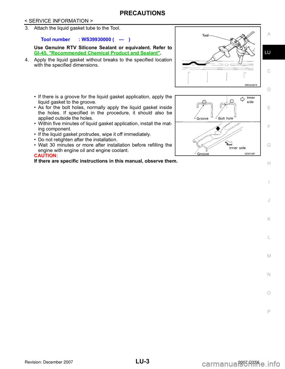
3. Attach the liquid gasket tube to the Tool.
Use Genuine RTV Silicone Sealant or equivalent. Refer to
GI-45, "
Recommended Chemical Product and Sealant".
4. Apply the liquid gasket without breaks to the specified location
with the specified dimensions.
• If there is a groove for the liquid gasket application, apply the
liquid gasket to the groove.
• As for the bolt holes, normally apply the liquid gasket inside
the holes. If specified in the procedure, it should also be
applied outside the holes.
• Within five minutes of liquid gasket application, install the mat-
ing component.
• If the liquid gasket protrudes, wipe it off immediately.
• Do not retighten after the installation.
• Wait 30 minutes or more after installation before refilling the
engine with engine oil and engine coolant.
CAUTION:
If there are specific instructions in this manual, observe them. Tool number : WS39930000 ( — )
WBIA0567E
SEM159F