2007 INFINITI QX56 DTC
[x] Cancel search: DTCPage 2167 of 3061
![INFINITI QX56 2007 Factory Service Manual LAN-36
< SERVICE INFORMATION >[CAN]
INDEX FOR DTC
SERVICE INFORMATION
INDEX FOR DTC
DTC No. IndexINFOID:0000000003533619
DTCSelf-diagnosis item
(CONSULT-II indication)DTC detection condition Inspecti INFINITI QX56 2007 Factory Service Manual LAN-36
< SERVICE INFORMATION >[CAN]
INDEX FOR DTC
SERVICE INFORMATION
INDEX FOR DTC
DTC No. IndexINFOID:0000000003533619
DTCSelf-diagnosis item
(CONSULT-II indication)DTC detection condition Inspecti](/manual-img/42/57029/w960_57029-2166.png)
LAN-36
< SERVICE INFORMATION >[CAN]
INDEX FOR DTC
SERVICE INFORMATION
INDEX FOR DTC
DTC No. IndexINFOID:0000000003533619
DTCSelf-diagnosis item
(CONSULT-II indication)DTC detection condition Inspection
U1000 CAN COMM CIRCUITWhen ECM is not transmitting or receiving CAN
communication signal of OBD (emission-related
diagnosis) for 2 seconds or more.
Refer to LAN-37
. When a control unit (except for ECM) is not
transmitting or receiving CAN communication
signal for 2 seconds or more.
U1001 CAN COMM CIRCUITWhen ECM is not transmitting or receiving CAN
communication signal other than OBD (emis-
sion-related diagnosis) for 2 seconds or more.
U1002 SYSTEM COMMWhen a control unit is not transmitting or receiv-
ing CAN communication signal for 2 seconds or
less.Start the inspection. Re-
fer to the applicable sec-
tion of the indicated
control unit.
U1010 CONTROL UNIT [CAN]When an error is detected during the initial diag-
nosis for CAN controller of each control unit.Replace the control unit
indicating “U1010”.
Page 2227 of 3061
LT-20
< SERVICE INFORMATION >
HEADLAMP (FOR USA)
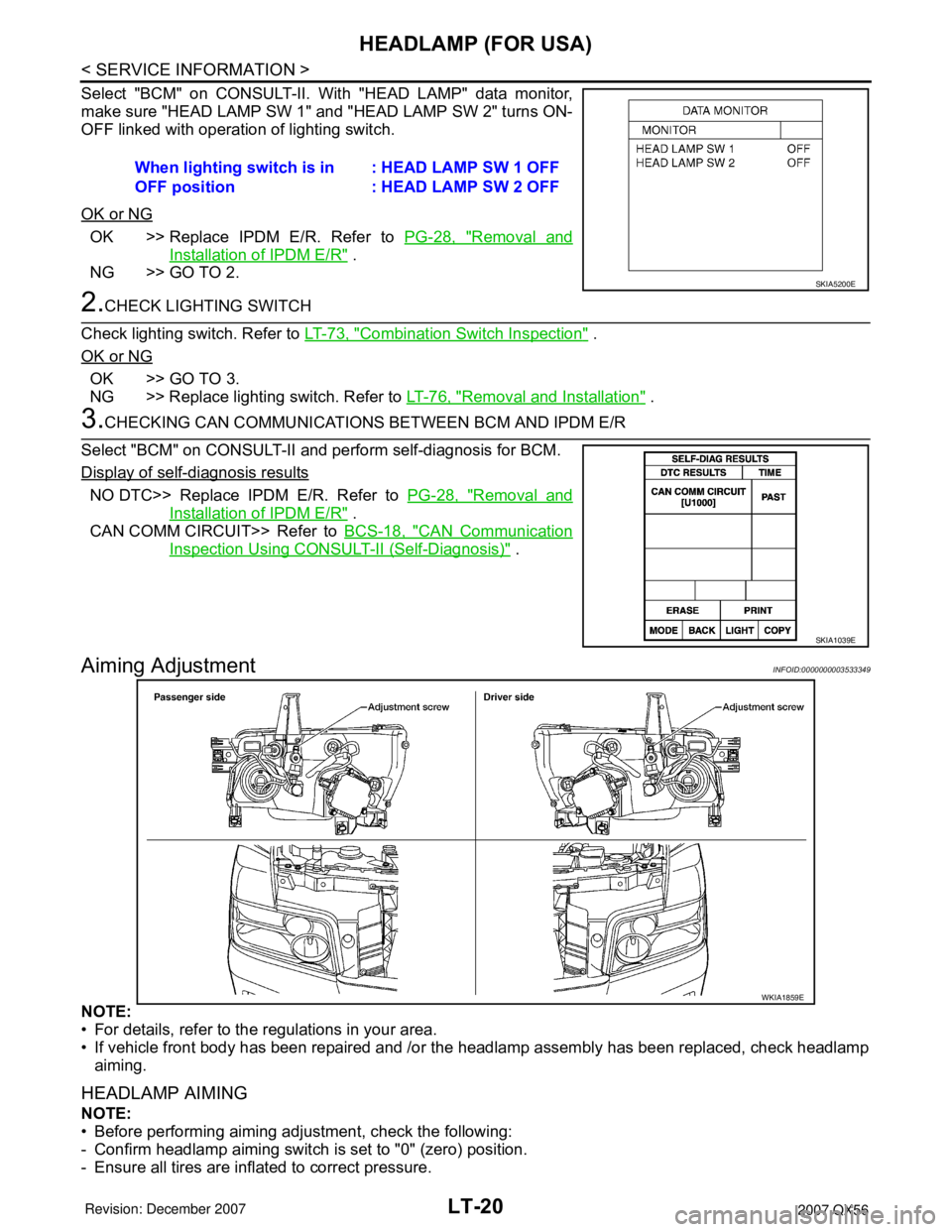
Select "BCM" on CONSULT-II. With "HEAD LAMP" data monitor,
make sure "HEAD LAMP SW 1" and "HEAD LAMP SW 2" turns ON-
OFF linked with operation of lighting switch.
OK or NG
OK >> Replace IPDM E/R. Refer to PG-28, "Removal and
Installation of IPDM E/R" .
NG >> GO TO 2.
2.CHECK LIGHTING SWITCH
Check lighting switch. Refer to LT-73, "
Combination Switch Inspection" .
OK or NG
OK >> GO TO 3.
NG >> Replace lighting switch. Refer to LT-76, "
Removal and Installation" .
3.CHECKING CAN COMMUNICATIONS BETWEEN BCM AND IPDM E/R
Select "BCM" on CONSULT-II and perform self-diagnosis for BCM.
Display of self-diagnosis results
NO DTC>> Replace IPDM E/R. Refer to PG-28, "Removal and
Installation of IPDM E/R" .
CAN COMM CIRCUIT>> Refer to BCS-18, "
CAN Communication
Inspection Using CONSULT-II (Self-Diagnosis)" .
Aiming AdjustmentINFOID:0000000003533349
NOTE:
• For details, refer to the regulations in your area.
• If vehicle front body has been repaired and /or the headlamp assembly has been replaced, check headlamp
aiming.
HEADLAMP AIMING
NOTE:
• Before performing aiming adjustment, check the following:
- Confirm headlamp aiming switch is set to "0" (zero) position.
- Ensure all tires are inflated to correct pressure.When lighting switch is in
OFF position: HEAD LAMP SW 1 OFF
: HEAD LAMP SW 2 OFF
SKIA5200E
SKIA1039E
WKIA1859E
Page 2240 of 3061
HEADLAMP (FOR CANADA) - DAYTIME LIGHT SYSTEM -
LT-33
< SERVICE INFORMATION >
C
D
E
F
G
H
I
J
L
MA
B
LT
N
O
P
1. Connect daytime light relay and IPDM E/R connector.
2. Apply parking brake and start engine. Headlamp switch OFF.
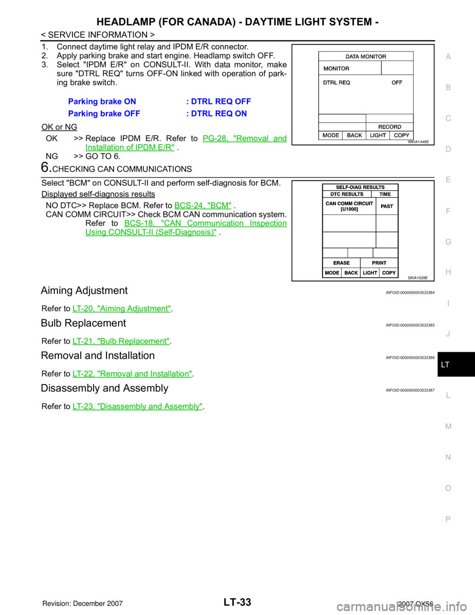
3. Select "IPDM E/R" on CONSULT-II. With data monitor, make
sure "DTRL REQ" turns OFF-ON linked with operation of park-
ing brake switch.
OK or NG
OK >> Replace IPDM E/R. Refer to PG-28, "Removal and
Installation of IPDM E/R" .
NG >> GO TO 6.
6.CHECKING CAN COMMUNICATIONS
Select "BCM" on CONSULT-II and perform self-diagnosis for BCM.
Displayed self-diagnosis results
NO DTC>> Replace BCM. Refer to BCS-24, "BCM" .
CAN COMM CIRCUIT>> Check BCM CAN communication system.
Refer to BCS-18, "
CAN Communication Inspection
Using CONSULT-II (Self-Diagnosis)" .
Aiming AdjustmentINFOID:0000000003533364
Refer to LT-20, "Aiming Adjustment".
Bulb ReplacementINFOID:0000000003533365
Refer to LT-21, "Bulb Replacement".
Removal and InstallationINFOID:0000000003533366
Refer to LT-22, "Removal and Installation".
Disassembly and AssemblyINFOID:0000000003533367
Refer to LT-23, "Disassembly and Assembly". Parking brake ON : DTRL REQ OFF
Parking brake OFF : DTRL REQ ON
WKIA1449E
SKIA1039E
Page 2421 of 3061

IPDM E/R (INTELLIGENT POWER DISTRIBUTION MODULE ENGINE ROOM)
PG-19
< SERVICE INFORMATION >
C
D
E
F
G
H
I
J
L
MA
B
PG
N
O
P
NOTE:
The details for display of the period are as follows:
• CRNT: Error currently detected with IPDM E/R.
• PAST: Error detected in the past and placed in IPDM E/R memory.
DATA MONITOR
All Signals, Main Signals, Selection From Menu
Display itemsCONSULT-II
display codeMalfunction detectionTIME
Possible causes
CRNT PAST
NO DTC IS DETECTED.
FURTHER TESTING
MAY BE REQUIRED.—————
CAN COMM CIRC U1000• If CAN communication reception/transmission
data has a malfunction, or if any of the control
units fail, data reception/transmission cannot
be confirmed.
• When the data in CAN communication is not
received before the specified time.XXAny of items listed be-
low have errors:
• TRANSMIT DIAG
•ECM
•BCM/SEC
ALL SIGNALS All signals will be monitored.
MAIN SIGNALS Monitors the predetermined item(s).
SELECTION FROM MENU Selects and monitors individual signal(s).
Item nameCONSULT-II
screen displayDisplay or unitMonitor item selection
Description
ALL
SIGNALSMAIN
SIGNALSSELECTION
FROM MENU
Motor fan requestMOTOR FAN
REQ1/2/3/4 X X X Signal status input from ECM
Compressor re-
questAC COMP REQ ON/OFF X X X Signal status input from ECM
Parking, license,
and tail lamp re-
questTAIL & CLR REQ ON/OFF X X X Signal status input from BCM
Headlamp low
beam requestHL LO REQ ON/OFF X X X Signal status input from BCM
Headlamp high
beam requestHL HI REQ ON/OFF X X X Signal status input from BCM
Front fog request FR FOG REQ ON/OFF X X X Signal status input from BCM
Front wiper re-
questFR WIP REQSTOP/1LOW/
LOW/HIX X X Signal status input from BCM
Wiper auto stopWIP AUTO
STOPACT P/STOP P X X X Output status of IPDM E/R
Wiper protection WIP PROT OFF/Block X X X Control status of IPDM E/R
Starter request ST RLY REQ ON/OFF X X
Status of input signal
NOTE
Ignition relay
statusIGN RLY ON/OFF X X XIgnition relay status monitored
with IPDM E/R
Rear defogger re-
questRR DEF REQ ON/OFF X X X Signal status input from BCM
Oil pressure
switchOIL P SW (*1) OPEN/CLOSE X XSignal status input from IPDM
E/R
Hood switch HOOD SW OFF XSignal status input from IPDM
E/R
Page 2429 of 3061
IPDM E/R (INTELLIGENT POWER DISTRIBUTION MODULE ENGINE ROOM)
PG-27
< SERVICE INFORMATION >
C
D
E
F
G
H
I
J
L
MA
B
PG
N
O
P
OK or NG
OK >> GO TO 2.
NG >> Replace fuse or fusible link.
2.POWER CIRCUIT INSPECTION
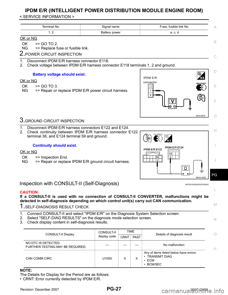
1. Disconnect IPDM E/R harness connector E118.
2. Check voltage between IPDM E/R harness connector E118 terminals 1, 2 and ground.
OK or NG
OK >> GO TO 3.
NG >> Repair or replace IPDM E/R power circuit harness.
3.GROUND CIRCUIT INSPECTION
1. Disconnect IPDM E/R harness connectors E122 and E124.
2. Check continuity between IPDM E/R harness connector E122
terminal 38, and E124 terminal 59 and ground.
OK or NG
OK >> Inspection End.
NG >> Repair or replace IPDM E/R ground circuit harness.
Inspection with CONSULT-II (Self-Diagnosis)INFOID:0000000003533843
CAUTION:
If a CONSULT-II is used with no connection of CONSULT-II CONVERTER, malfunctions might be
detected in self-diagnosis depending on which control unit(s) carry out CAN communication.
1.SELF-DIAGNOSIS RESULT CHECK
1. Connect CONSULT-II and select "IPDM E/R" on the Diagnosis System Selection screen.
2. Select "SELF-DIAG RESULTS" on the diagnosis mode selection screen.
3. Check display content in self-diagnosis results.
NOTE:
The Details for Display for the Period are as follows:
• CRNT: Error currently detected by IPDM E/R.
Terminal No. Signal name Fuse, fusible link No.
1, 2 Battery power a, c, d
Battery voltage should exist.
SKIA1987E
Continuity should exist.
WKIA1453E
CONSULT-II DisplayCONSULT-II
display codeTIME
Details of diagnosis result
CRNT PAST
NO DTC IS DETECTED.
FURTHER TESTING MAY BE REQUIRED.——— No malfunction
CAN COMM CIRC U1000 X XAny of items listed below have errors:
• TRANSMIT DIAG
•ECM
• BCM/SEC
Page 2430 of 3061
PG-28
< SERVICE INFORMATION >
IPDM E/R (INTELLIGENT POWER DISTRIBUTION MODULE ENGINE ROOM)
• PAST: Error detected in the past and stored in IPDM E/R memory.
Contents displayed
NO DTC DETECTED. FURTHER TESTING MAY BE REQUIRED.>>Inspection End.
CAN COMM CIRC>>Print out the self-diagnosis result and refer to LAN-40
.
Removal and Installation of IPDM E/RINFOID:0000000003533844
REMOVAL
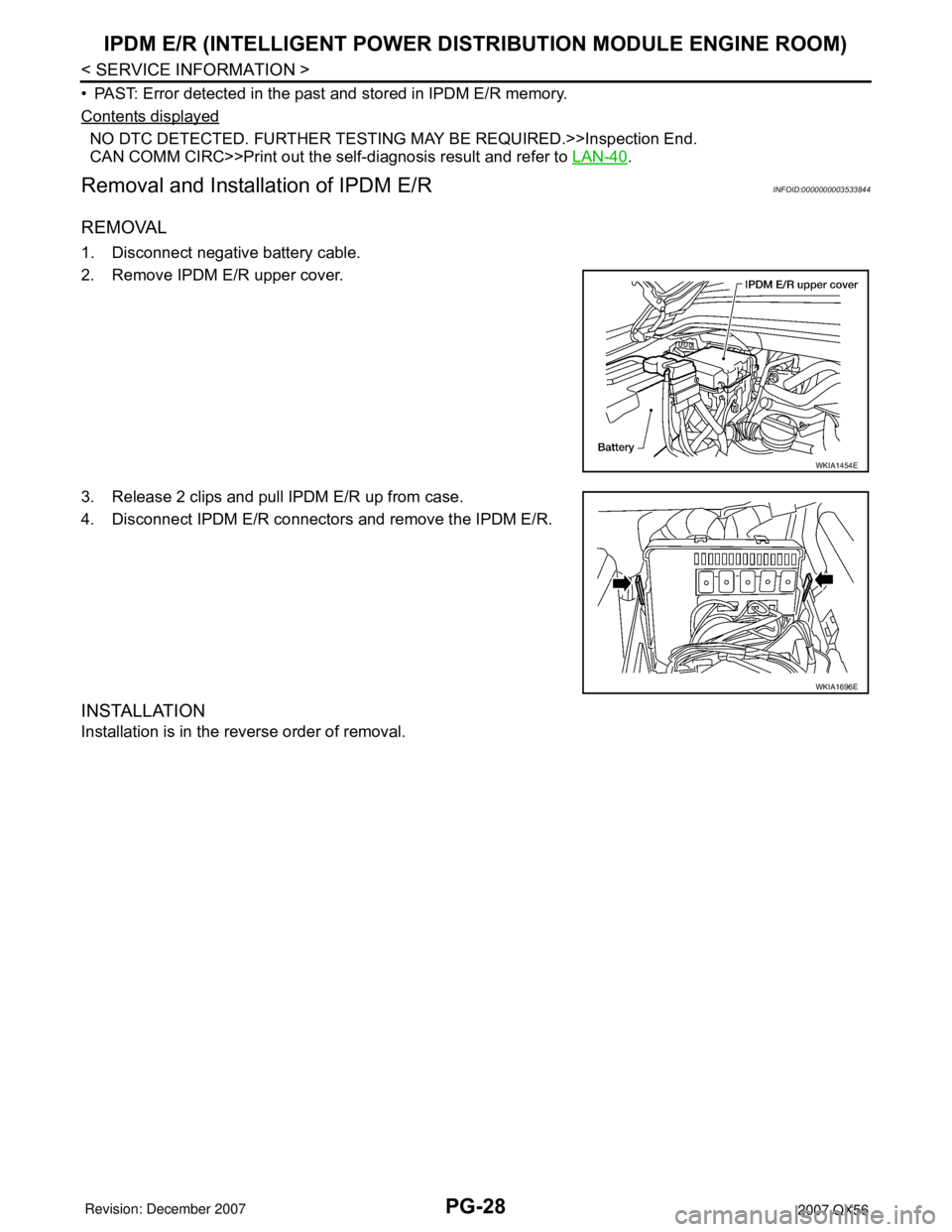
1. Disconnect negative battery cable.
2. Remove IPDM E/R upper cover.
3. Release 2 clips and pull IPDM E/R up from case.
4. Disconnect IPDM E/R connectors and remove the IPDM E/R.
INSTALLATION
Installation is in the reverse order of removal.
WKIA1454E
WKIA1696E
Page 2666 of 3061
SC-18
< SERVICE INFORMATION >
CHARGING SYSTEM
Before starting, perform the preliminary inspection. Refer to "PRELIMINARY INSPECTION".
1. Stop the operation of the power generation variable voltage control system using either of the following
procedures.
• Using the CONSULT-II, select "ENGINE" from "SELECT SYSTEM" and set the "ALT DUTY" to 0%.
Keep "ALT DUTY" at 0% until the end of the inspection. When the "ALT DUTY" value is 0% or 100%,
normal power generation is performed according to the characteristic of the IC regulator in the genera-
tor.
• Turn the ignition switch off, and disconnect the battery current sensor connector. Disconnecting the bat-
tery current sensor may cause DTC (P1550 - P1554) to set. After finishing the inspection, connect the
battery current sensor connector and erase the self-diagnostic results history of the engine using CON-
SULT-II.
2. Turn off all loads on the vehicle electrical system.
3. Perform battery and starting system test with Battery/Starting/
Charging system tester.
4. Press “ENTER” to begin the charging system test.
5. Start engine.
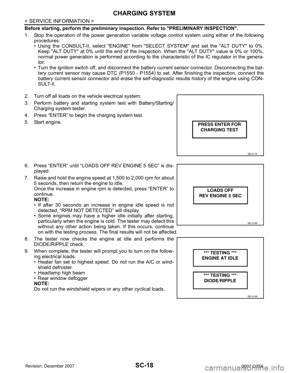
6. Press “ENTER” until “LOADS OFF REV ENGINE 5 SEC” is dis-
played.
7. Raise and hold the engine speed at 1,500 to 2,000 rpm for about
5 seconds, then return the engine to idle.
Once the increase in engine rpm is detected, press “ENTER” to
continue.
NOTE:
• If after 30 seconds an increase in engine idle speed is not
detected, “RPM NOT DETECTED” will display.
• Some engines may have a higher idle initially after starting,
particularly when the engine is cold. The tester may detect this
without any other action being taken. If this occurs, continue
on with the testing process. The final results will not be affected.
8. The tester now checks the engine at idle and performs the
DIODE/RIPPLE check.
9. When complete, the tester will prompt you to turn on the follow-
ing electrical loads.
• Heater fan set to highest speed. Do not run the A/C or wind-
shield defroster.
• Headlamp high beam
• Rear window defogger
NOTE:
Do not run the windshield wipers or any other cyclical loads.
SEL417X
SEL418X
SEL419X
Page 2792 of 3061
![INFINITI QX56 2007 Factory Service Manual SRS-22
< SERVICE INFORMATION >
TROUBLE DIAGNOSIS
Diagnostic code is displayed on "SELF-DIAG [CURRENT]".
If no malfunction is detected on "SELF-DIAG [CURRENT]", but mal-
function is detected in "SRS Op INFINITI QX56 2007 Factory Service Manual SRS-22
< SERVICE INFORMATION >
TROUBLE DIAGNOSIS
Diagnostic code is displayed on "SELF-DIAG [CURRENT]".
If no malfunction is detected on "SELF-DIAG [CURRENT]", but mal-
function is detected in "SRS Op](/manual-img/42/57029/w960_57029-2791.png)
SRS-22
< SERVICE INFORMATION >
TROUBLE DIAGNOSIS
Diagnostic code is displayed on "SELF-DIAG [CURRENT]".
If no malfunction is detected on "SELF-DIAG [CURRENT]", but mal-
function is detected in "SRS Operation Check", the following cases
may exist:
• "SELF-DIAG [PAST]" memory might not be erased.
• The SRS system malfunctions intermittently.
Refer to "DIAGNOSTIC PROCEDURE 4".
CONSULT-II Diagnostic Code Chart
WHIA0151E
SRS701
Diagnostic item ExplanationRepair order
Recheck SRS at each replacement
NO DTC IS DETECTEDMalfunction is indicat-
ed by the “AIR BAG”
warning lamp in User
mode.Low battery voltage (Less than 9V) 1. Go to SC-4
.
2. Go to "DIAGNOSTIC PROCE-
DURE 3" .
“SELF-DIAG [PAST]” memory might
not be erased.Go to "DIAGNOSTIC PROCEDURE 4"
.
Intermittent malfunction has been
detected in the past.Go to "DIAGNOSTIC PROCEDURE 5"
.
No malfunction is detected in User mode. —
DRIVER AIRBAG MODULE
[OPEN]
[B1049] or [B1054]Driver air bag module circuit is open (including the spiral ca-
ble).1. Visually check the wiring harness
connection.
2. Replace the harness if it has visi-
ble damage.
3. Replace driver air bag module.
4. Replace the spiral cable.
5. Replace the air bag diagnosis
sensor unit.
6. Replace the related harness. DRIVER AIRBAG MODULE
[VB-SHORT]
[B1050] or [B1055]Driver air bag module circuit is shorted to some power supply
circuit (including the spiral cable).
DRIVER AIRBAG MODULE
[GND-SHORT]
[B1051] or [B1056]Driver air bag module circuit is shorted to ground (including
the spiral cable).
DRIVER AIRBAG MODULE
[SHORT]
[B1052] or [B1057]Driver air bag module circuits are shorted to each other.