2007 INFINITI QX56 headlamp
[x] Cancel search: headlampPage 2236 of 3061
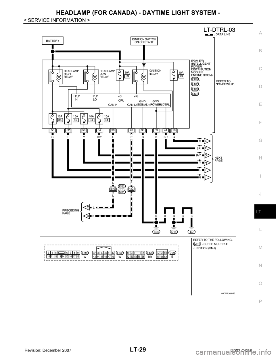
HEADLAMP (FOR CANADA) - DAYTIME LIGHT SYSTEM -
LT-29
< SERVICE INFORMATION >
C
D
E
F
G
H
I
J
L
MA
B
LT
N
O
P
WKWA3644E
Page 2237 of 3061
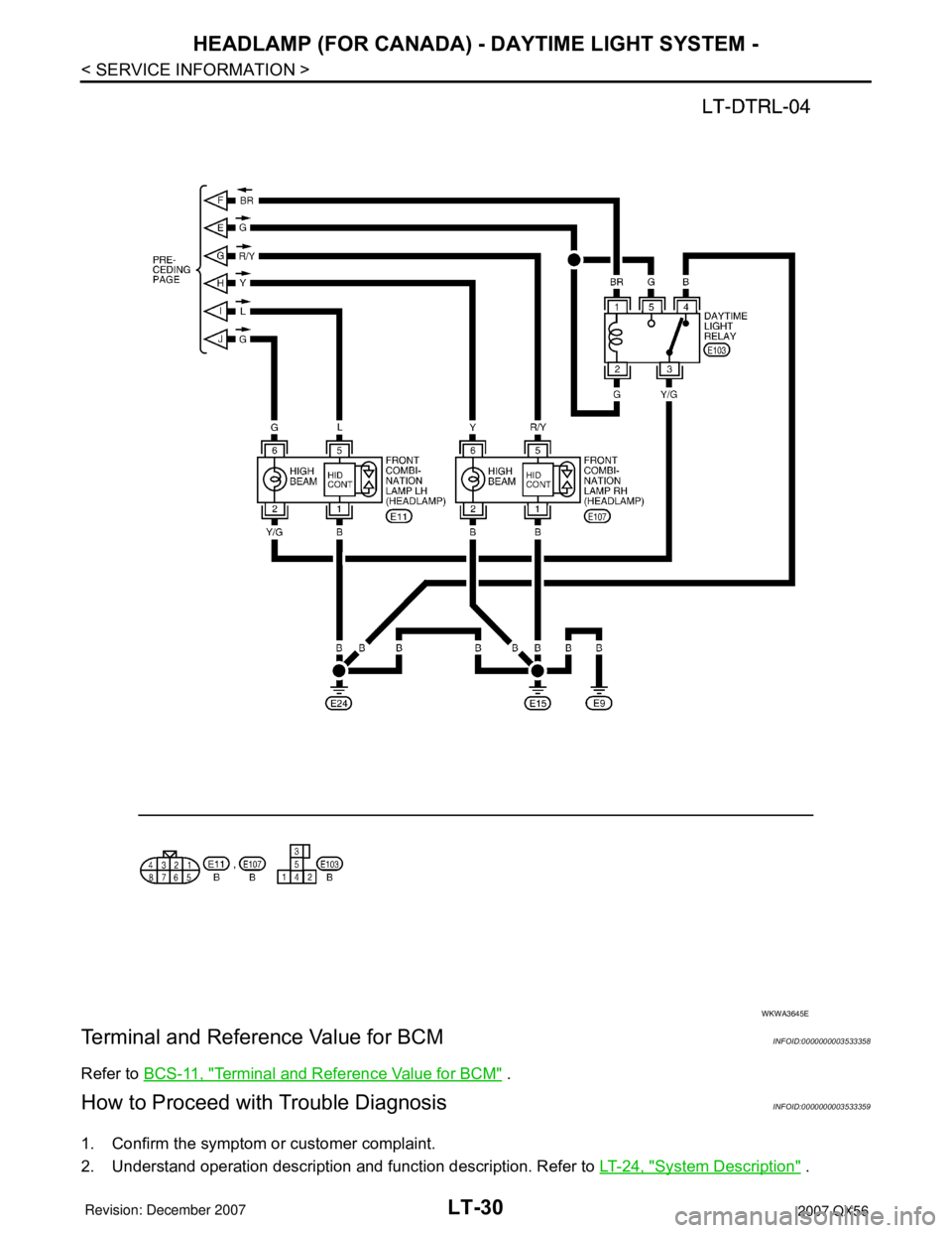
LT-30
< SERVICE INFORMATION >
HEADLAMP (FOR CANADA) - DAYTIME LIGHT SYSTEM -
Terminal and Reference Value for BCM
INFOID:0000000003533358
Refer to BCS-11, "Terminal and Reference Value for BCM" .
How to Proceed with Trouble DiagnosisINFOID:0000000003533359
1. Confirm the symptom or customer complaint.
2. Understand operation description and function description. Refer to LT-24, "
System Description" .
WKWA3645E
Page 2238 of 3061
HEADLAMP (FOR CANADA) - DAYTIME LIGHT SYSTEM -
LT-31
< SERVICE INFORMATION >
C
D
E
F
G
H
I
J
L
MA
B
LT
N
O
P
3. Perform the Preliminary Check. Refer to LT-31, "Preliminary Check" .
4. Check symptom and repair or replace the cause of malfunction.
5. Does the headlamp operate normally? If YES: GO TO 6. If NO: GO TO 4.
6. Inspection End.
Preliminary CheckINFOID:0000000003533360
CHECK BCM CONFIGURATION
1.CHECK BCM CONFIGURATION
Confirm BCM configuration for "DTRL" is set to "WITH". Refer to BCS-18, "
Configuration" .
OK or NG
OK >> Continue preliminary check. Refer to BCS-15, "BCM Power Supply and Ground Circuit Inspec-
tion" .
NG >> Change BCM configuration for "DTRL" to "WITH". Refer to BCS-18, "
Configuration" .
INSPECT POWER SUPPLY AND GROUND CIRCUIT FOR BCM
Refer to BCS-15, "BCM Power Supply and Ground Circuit Inspection".
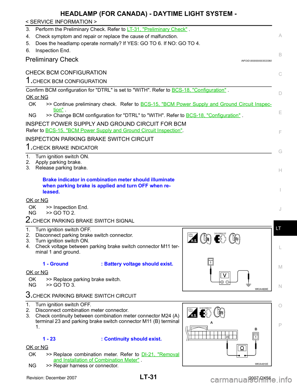
INSPECTION PARKING BRAKE SWITCH CIRCUIT
1.CHECK BRAKE INDICATOR
1. Turn ignition switch ON.
2. Apply parking brake.
3. Release parking brake.
OK or NG
OK >> Inspection End.
NG >> GO TO 2.
2.CHECK PARKING BRAKE SWITCH SIGNAL
1. Turn ignition switch OFF.
2. Disconnect parking brake switch connector.
3. Turn ignition switch ON.
4. Check voltage between parking brake switch connector M11 ter-
minal 1 and ground.
OK or NG
OK >> Replace parking brake switch.
NG >> GO TO 3.
3.CHECK PARKING BRAKE SWITCH CIRCUIT
1. Turn ignition switch OFF.
2. Disconnect combination meter connector.
3. Check continuity between combination meter connector M24 (A)
terminal 23 and parking brake switch connector M11 (B) terminal
1.
OK or NG
OK >> Replace combination meter. Refer to DI-21, "Removal
and Installation of Combination Meter" .
NG >> Repair harness or connector.Brake indicator in combination meter should illuminate
when parking brake is applied and turn OFF when re-
leased.
1 - Ground : Battery voltage should exist.
WKIA4609E
1 - 23 : Continuity should exist.
WKIA4610E
Page 2239 of 3061
LT-32
< SERVICE INFORMATION >
HEADLAMP (FOR CANADA) - DAYTIME LIGHT SYSTEM -
CONSULT-II Function for BCM
INFOID:0000000003533361
Refer to BCS-16, "CONSULT-II Function (BCM)" .
CONSULT-II Function for IPDM E/RINFOID:0000000003533362
Refer to PG-18, "CONSULT-II Function (IPDM E/R)" .
Daytime Light Control Does Not Operate Properly (Normal Headlamps Operate Prop-
erly)
INFOID:0000000003533363
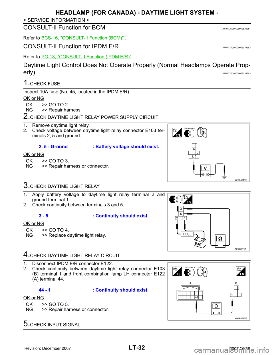
1.CHECK FUSE
Inspect 10A fuse (No. 45, located in the IPDM E/R).
OK or NG
OK >> GO TO 2.
NG >> Repair harness.
2.CHECK DAYTIME LIGHT RELAY POWER SUPPLY CIRCUIT
1. Remove daytime light relay.
2. Check voltage between daytime light relay connector E103 ter-
minals 2, 5 and ground.
OK or NG
OK >> GO TO 3.
NG >> Repair harness or connector.
3.CHECK DAYTIME LIGHT RELAY
1. Apply battery voltage to daytime light relay terminal 2 and
ground terminal 1.
2. Check continuity between terminals 3 and 5.
OK or NG
OK >> GO TO 4.
NG >> Replace daytime light relay.
4.CHECK DAYTIME LIGHT RELAY CIRCUIT
1. Disconnect IPDM E/R connector E122.
2. Check continuity between daytime light relay connector E103
(B) terminal 1 and front combination lamp LH connector E122
(A) terminal 44.
OK or NG
OK >> GO TO 5.
NG >> Repair harness or connector.
5.CHECK INPUT SIGNAL 2, 5 - Ground : Battery voltage should exist.
WKIA4611E
3 - 5 : Continuity should exist.
SKIB4671E
44 - 1 : Continuity should exist.
WKIA4612E
Page 2240 of 3061
HEADLAMP (FOR CANADA) - DAYTIME LIGHT SYSTEM -
LT-33
< SERVICE INFORMATION >
C
D
E
F
G
H
I
J
L
MA
B
LT
N
O
P
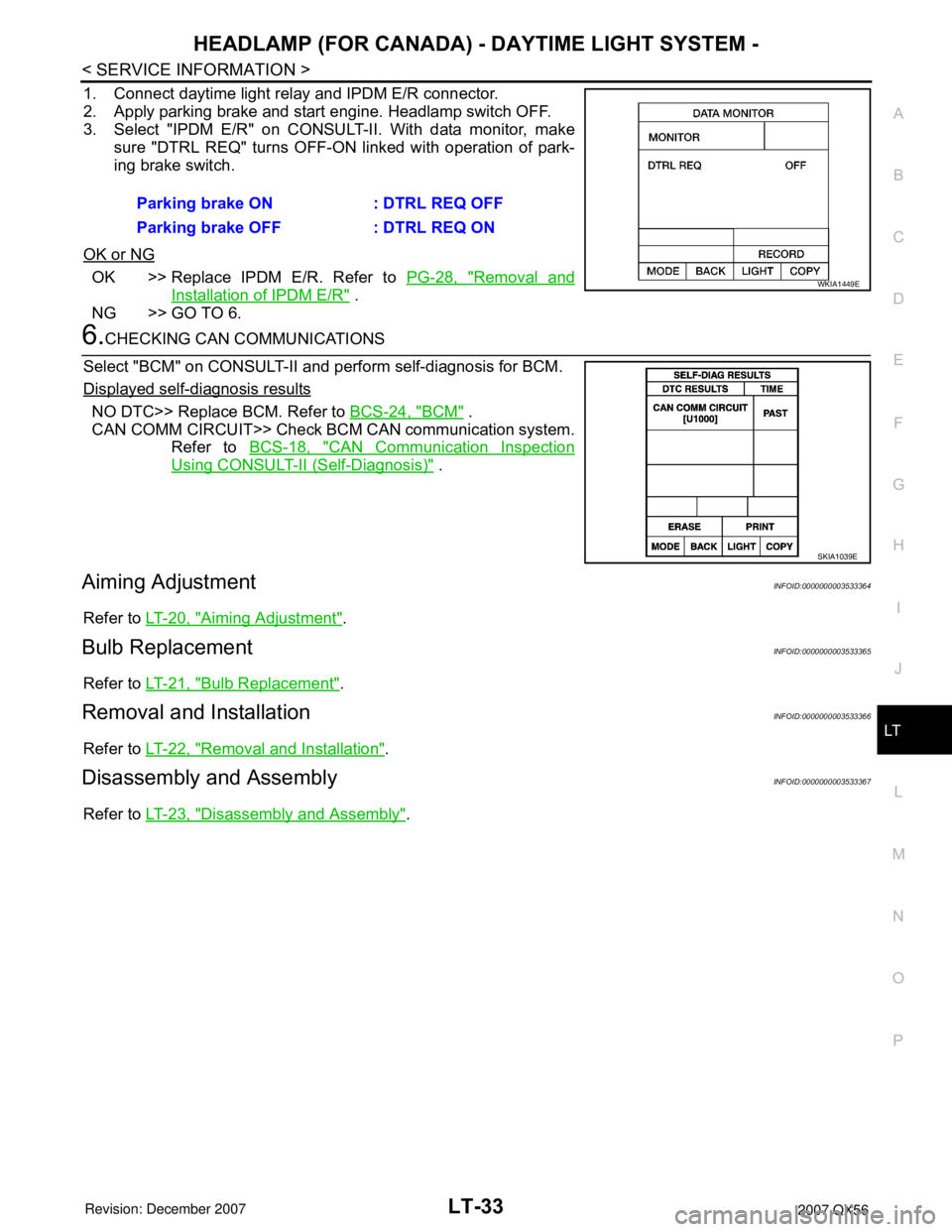
1. Connect daytime light relay and IPDM E/R connector.
2. Apply parking brake and start engine. Headlamp switch OFF.
3. Select "IPDM E/R" on CONSULT-II. With data monitor, make
sure "DTRL REQ" turns OFF-ON linked with operation of park-
ing brake switch.
OK or NG
OK >> Replace IPDM E/R. Refer to PG-28, "Removal and
Installation of IPDM E/R" .
NG >> GO TO 6.
6.CHECKING CAN COMMUNICATIONS
Select "BCM" on CONSULT-II and perform self-diagnosis for BCM.
Displayed self-diagnosis results
NO DTC>> Replace BCM. Refer to BCS-24, "BCM" .
CAN COMM CIRCUIT>> Check BCM CAN communication system.
Refer to BCS-18, "
CAN Communication Inspection
Using CONSULT-II (Self-Diagnosis)" .
Aiming AdjustmentINFOID:0000000003533364
Refer to LT-20, "Aiming Adjustment".
Bulb ReplacementINFOID:0000000003533365
Refer to LT-21, "Bulb Replacement".
Removal and InstallationINFOID:0000000003533366
Refer to LT-22, "Removal and Installation".
Disassembly and AssemblyINFOID:0000000003533367
Refer to LT-23, "Disassembly and Assembly". Parking brake ON : DTRL REQ OFF
Parking brake OFF : DTRL REQ ON
WKIA1449E
SKIA1039E
Page 2241 of 3061
LT-34
< SERVICE INFORMATION >
AUTO LIGHT SYSTEM
AUTO LIGHT SYSTEM
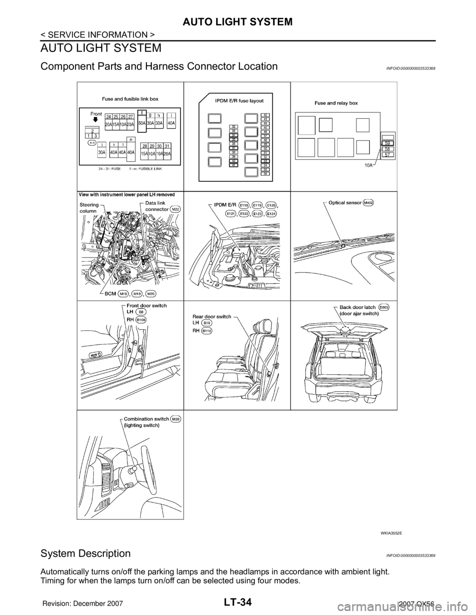
Component Parts and Harness Connector LocationINFOID:0000000003533368
System DescriptionINFOID:0000000003533369
Automatically turns on/off the parking lamps and the headlamps in accordance with ambient light.
Timing for when the lamps turn on/off can be selected using four modes.
WKIA3552E
Page 2242 of 3061
AUTO LIGHT SYSTEM
LT-35
< SERVICE INFORMATION >
C
D
E
F
G
H
I
J
L
MA
B
LT
N
O
P
OUTLINE
The auto light control system uses an optical sensor that detects outside brightness.
When the lighting switch is in "AUTO" position, it automatically turns on/off the parking lamps and the head-
lamps in accordance with the ambient light. Sensitivity can be adjusted in four steps. For the details of the set-
ting, refer to LT-40, "
Preliminary Check" .
Optical sensor ground is supplied
• to optical sensor terminal 3
• through BCM (body control module) terminal 18.
When ignition switch is turned to “ON” position and when outside brightness is darker than prescribed level,
input is supplied
• to BCM terminal 58
• through optical sensor terminal 4.
The headlamps will then illuminate. For a description of headlamp operation, refer to LT- 5 , "
System Descrip-
tion" .
COMBINATION SWITCH READING FUNCTION
Refer to BCS-3, "System Description" .
EXTERIOR LAMP BATTERY SAVER CONTROL
When the combination switch (lighting switch) is in the AUTO position, and the ignition switch is turned from
ON or ACC to OFF, and one of the front doors is opened, the battery saver control feature is activated.
Under this condition, the headlamps remain illuminated for 5 minutes, then the headlamps are turned off.
Exterior lamp battery saver control mode can be changed by the function setting of CONSULT-II.
DELAY TIMER FUNCTION
When the ignition switch is ON and auto light switch is ON, the BCM turns on/off the headlamps. In delay timer
function, ignition is OFF, auto light sensor power source is OFF and the headlamps are not turned on/off by the
BCM. On condition that:
• when the state of ignition switch ON or ACC is ON and output judgment by auto light function is headlamp
ON changes to ignition switch and ACC are OFF and any door switch is ON, output judgment by BCM
should be headlamp ON for 5 minutes by timer. After time out, output judgment by BCM should be headlamp
OFF.
• when the state of any door switch is turned to ON from OFF while 45 second or 5 minute timer is counting,
timer stops, and restarts counting for 5 minutes, then BCM judges output as headlamp ON. After time out,
BCM judges output as headlamp OFF.
• when the state of front door switch (LH), front door switch (RH), rear door switch LH, rear door switch RH or
back door latch (door ajar switch) is ON turns to all door switches are OFF while 45 second or 5 minute timer
is counting, timer stops, and restarts counting for 45 seconds, then BCM judges output as headlamp ON.
After timer out, BCM judges output as headlamp OFF.
• when the state is ignition switch ON or ACC is ON or auto light switch OFF while timer is counting, timer
stops counting and BCM turns on/off lamps according to headlamp function, front fog lamp function, auto
light function and headlamp battery save function.
Delay timer control mode can be changed by the function setting of CONSULT-II.
CAN Communication System DescriptionINFOID:0000000003533370
Refer to LAN-4, "CAN Communication System" .
Major Component and FunctionsINFOID:0000000003533371
Components Functions
BCM• Turns on/off circuits of tail light and headlamp according to signals from light sensor, lighting switch
(AUTO), front door switch LH, front door switch RH, rear door switch, back door latch (door ajar
switch), and ignition switch (ON, OFF).
Optical sensor • Converts ambient light (lux) to voltage, and sends it to BCM. (Detects lightness of 50 to 1,300 lux)
Page 2247 of 3061

LT-40
< SERVICE INFORMATION >
AUTO LIGHT SYSTEM
How to Proceed with Trouble Diagnosis
INFOID:0000000003533376
1. Confirm the symptom or customer complaint.
2. Understand operation description and function description. Refer to LT-34, "
System Description" .
3. Carry out the Preliminary Check. Refer to LT-40, "
Preliminary Check" .
4. Check symptom and repair or replace the component. Refer to LT-42, "
Trouble Diagnosis Chart by Symp-
tom" .
5. Does the auto light system operate normally? If YES: GO TO 6. If NO: GO TO 4.
6. Inspection End.
Preliminary CheckINFOID:0000000003533377
SETTING CHANGE FUNCTIONS
• Sensitivity of auto light system can be adjusted using CONSULT-II. Refer to LT-40, "CONSULT-II Function
(BCM)" .
CHECK POWER SUPPLY AND GROUND CIRCUIT FOR BCM
Refer to BCS-15, "BCM Power Supply and Ground Circuit Inspection" .
CHECK POWER SUPPLY AND GROUND CIRCUIT FOR IPDM E/R
Refer to PG-26, "IPDM E/R Power/Ground Circuit Inspection" .
CONSULT-II Function (BCM)INFOID:0000000003533378
Refer to BCS-16, "CONSULT-II Function (BCM)".
CONSULT-II START PROCEDURE
Refer to GI-36, "CONSULT-II Start Procedure" .
WORK SUPPORT
Work Support Setting Item
• Delay timer setting can be selected and set from eight modes.
• Sensitivity of auto light can be selected and set from four modes.
DATA MONITOR
Display Item List
Work item Description
CUSTOM A/LIGHT SETTINGAuto light sensitivity can be changed in this mode. Sensitivity can be adjusted in four modes.
• MODE 1 (Normal-default)/ MODE 2 (Desensitized)/MODE 3 (Sensitive)/MODE4 (Insensitive)
ILL DELAY SETAuto light delay off timer period can be changed in this mode. Selects auto light delay off timer period
among eight modes.
• MODE 1 (45 sec.)/MODE 2 (OFF)/MODE 3 (30 sec.)/MODE 4 (60 sec.)/MODE 5 (90 sec.)/MODE
6 (120 sec.)/MODE 7 (150 sec.)/MODE 8 (180 sec.)
Monitor item Contents
IGN ON SW "ON/OFF" Displays "IGN position (ON)/OFF, ACC position (OFF)" judged from the ignition switch signal.
ACC ON SW "ON/OFF" Displays "ACC (ON)/OFF, Ignition OFF (OFF)" status judged from ignition switch signal.
HI BEAM SW "ON/OFF"Displays status (high beam switch: ON/Others: OFF) of high beam switch judged from lighting
switch signal.
HEAD LAMP SW 1 "ON/OFF"Displays status (headlamp switch 1: ON/Others: OFF) of headlamp switch 2 judged from light-
ing switch signal.
HEAD LAMP SW 2 "ON/OFF"Displays status (headlamp switch 2: ON/Others: OFF) of headlamp switch 2 judged from light-
ing switch signal.
LIGHT SW 1ST "ON/OFF"Displays status (lighting switch 1st position: ON/Others: OFF) of lighting switch judged from
lighting switch signal.