2007 INFINITI QX56 headlamp
[x] Cancel search: headlampPage 2220 of 3061

HEADLAMP (FOR USA)
LT-13
< SERVICE INFORMATION >
C
D
E
F
G
H
I
J
L
MA
B
LT
N
O
P
ACTIVE TEST
Display Item List
SELF-DIAGNOSTIC RESULTS
Display Item List
CONSULT-II Function (IPDM E/R)INFOID:0000000003533342
Refer to PG-18, "CONSULT-II Function (IPDM E/R)" .
CONSULT-II START PROCEDURE
Refer to GI-36, "CONSULT-II Start Procedure".
DATA MONITOR
All Items, Main Items, Select Item Menu
NOTE:
Perform monitoring of IPDM E/R data with the ignition switch ON. When the ignition switch is at ACC, the dis-
play may not be correct.
DOOR SW-RR "ON/OFF"Displays status of the rear door as judged from the rear door switch (RH) signal. (Door is open:
ON/Door is closed: OFF)
DOOR SW-RL "ON/OFF"Displays status of the rear door as judged from the rear door switch (LH) signal. (Door is open:
ON/Door is closed: OFF)
BACK DOOR SW "ON/OFF"Displays status of the back door as judged from the back door switch signal. (Door is open: ON/
Door is closed: OFF)
TURN SIGNAL R "ON/OFF" Displays status (Turn right: ON/Others: OFF) as judged from lighting switch signal.
TURN SIGNAL L "ON/OFF" Displays status (Turn left: ON/Others: OFF) as judged from lighting switch signal.
CARGO LAMP SW "ON/OFF" Displays status of cargo lamp switch.
OPTICAL SENSOR [0 - 5V] Displays "ambient light (close to 5V when dark/close to 0V when light)" judged from optical sen-
sor signal. Monitor item Contents
Te s t i t e m D e s c r i p t i o n
TAIL LAMP Allows tail lamp relay to operate by switching ON-OFF.
HEAD LAMP Allows headlamp relay (HI, LO) to operate by switching ON-OFF.
FR FOG LAMP Allows fog lamp relay to operate by switching ON-OFF.
CARGO LAMP Allows cargo lamp to operate by switching ON-OFF.
CORNERING LAMP Not used.
Monitored item CONSULT-ll display Description
CAN communication CAN communication [U1000] Malfunction is detected in CAN communication.
CAN communication system CAN communication system 1 to 6 [U1000] Malfunction is detected in CAN system.
Item nameCONSULT-II
screen displayDisplay or
unitMonitor item selection
Description
ALL
SIGNALSMAIN
SIGNALSSELECTION
FROM MENU
Parking, license plate
and tail lamps requestTAIL&CLR REQ ON/OFF×× ×Signal status input from BCM
Headlamp low beam re-
questHL LO REQ ON/OFF×× ×Signal status input from BCM
Headlamp high beam re-
questHL HI REQ ON/OFF×× ×Signal status input from BCM
Daytime lights request DTRL REQ ON/OFF×–×Signal status input from BCM
Front fog lamps request FR FOG REQ ON/OFF×× ×Signal status input from BCM
Page 2221 of 3061
LT-14
< SERVICE INFORMATION >
HEADLAMP (FOR USA)
ACTIVE TEST
Headlamp HI Does Not Illuminate (Both Sides)INFOID:0000000003533343
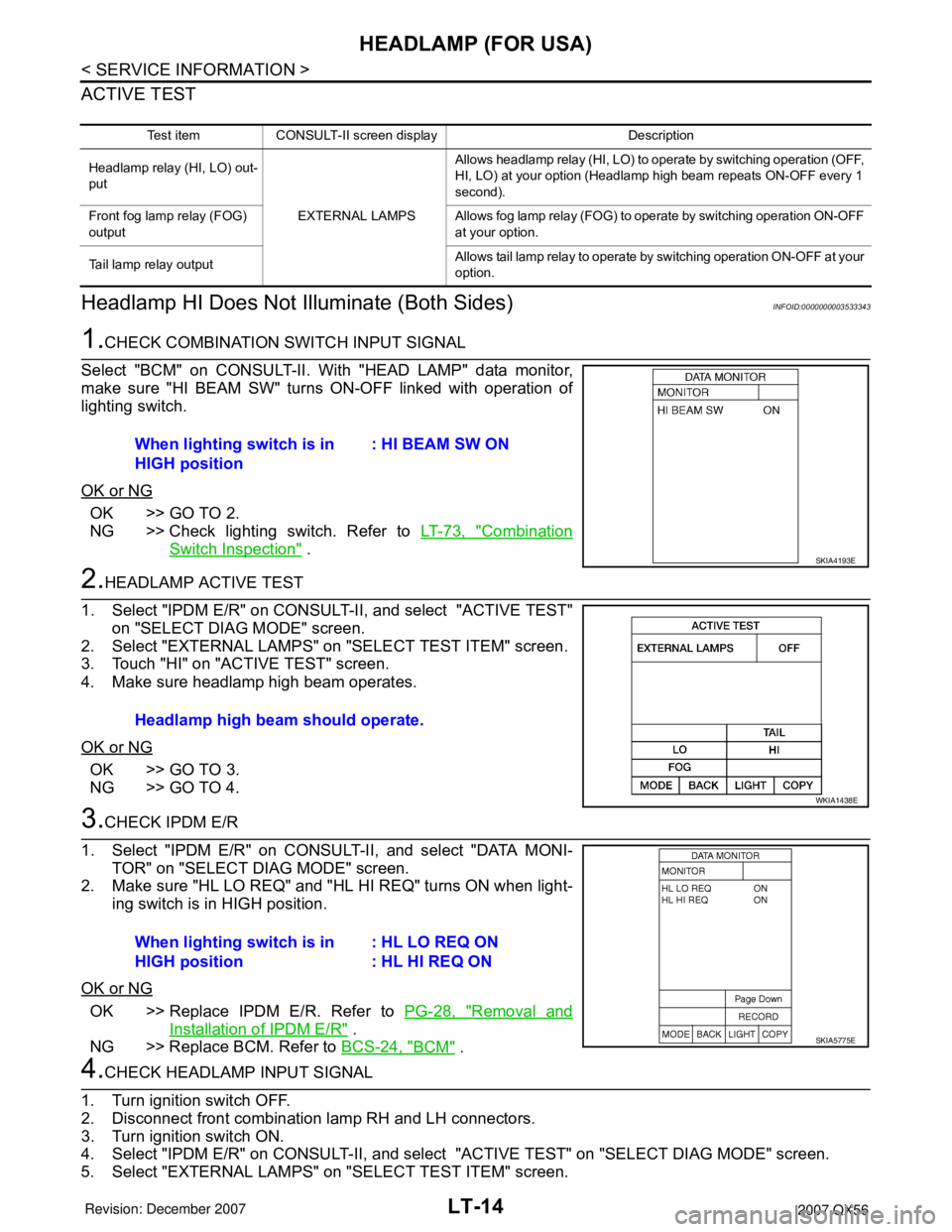
1.CHECK COMBINATION SWITCH INPUT SIGNAL
Select "BCM" on CONSULT-II. With "HEAD LAMP" data monitor,
make sure "HI BEAM SW" turns ON-OFF linked with operation of
lighting switch.
OK or NG
OK >> GO TO 2.
NG >> Check lighting switch. Refer to LT-73, "
Combination
Switch Inspection" .
2.HEADLAMP ACTIVE TEST
1. Select "IPDM E/R" on CONSULT-II, and select "ACTIVE TEST"
on "SELECT DIAG MODE" screen.
2. Select "EXTERNAL LAMPS" on "SELECT TEST ITEM" screen.
3. Touch "HI" on "ACTIVE TEST" screen.
4. Make sure headlamp high beam operates.
OK or NG
OK >> GO TO 3.
NG >> GO TO 4.
3.CHECK IPDM E/R
1. Select "IPDM E/R" on CONSULT-II, and select "DATA MONI-
TOR" on "SELECT DIAG MODE" screen.
2. Make sure "HL LO REQ" and "HL HI REQ" turns ON when light-
ing switch is in HIGH position.
OK or NG
OK >> Replace IPDM E/R. Refer to PG-28, "Removal and
Installation of IPDM E/R" .
NG >> Replace BCM. Refer to BCS-24, "
BCM" .
4.CHECK HEADLAMP INPUT SIGNAL
1. Turn ignition switch OFF.
2. Disconnect front combination lamp RH and LH connectors.
3. Turn ignition switch ON.
4. Select "IPDM E/R" on CONSULT-II, and select "ACTIVE TEST" on "SELECT DIAG MODE" screen.
5. Select "EXTERNAL LAMPS" on "SELECT TEST ITEM" screen.
Test item CONSULT-II screen display Description
Headlamp relay (HI, LO) out-
put
EXTERNAL LAMPSAllows headlamp relay (HI, LO) to operate by switching operation (OFF,
HI, LO) at your option (Headlamp high beam repeats ON-OFF every 1
second).
Front fog lamp relay (FOG)
outputAllows fog lamp relay (FOG) to operate by switching operation ON-OFF
at your option.
Tail lamp relay outputAllows tail lamp relay to operate by switching operation ON-OFF at your
option.
When lighting switch is in
HIGH position: HI BEAM SW ON
SKIA4193E
Headlamp high beam should operate.
WKIA1438E
When lighting switch is in
HIGH position: HL LO REQ ON
: HL HI REQ ON
SKIA5775E
Page 2222 of 3061
HEADLAMP (FOR USA)
LT-15
< SERVICE INFORMATION >
C
D
E
F
G
H
I
J
L
MA
B
LT
N
O
P
6. Touch "HI" on "ACTIVE TEST" screen.
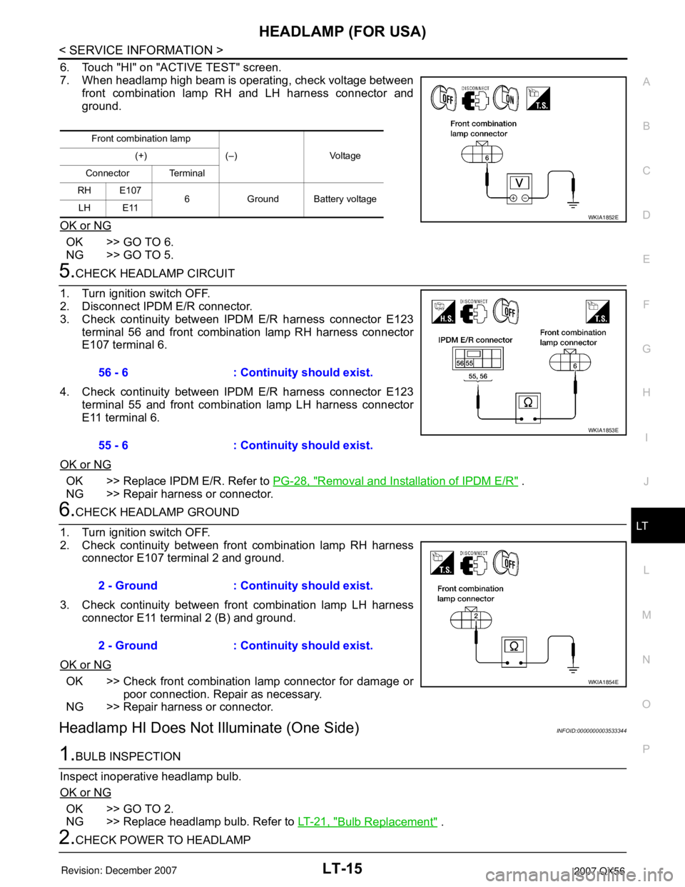
7. When headlamp high beam is operating, check voltage between
front combination lamp RH and LH harness connector and
ground.
OK or NG
OK >> GO TO 6.
NG >> GO TO 5.
5.CHECK HEADLAMP CIRCUIT
1. Turn ignition switch OFF.
2. Disconnect IPDM E/R connector.
3. Check continuity between IPDM E/R harness connector E123
terminal 56 and front combination lamp RH harness connector
E107 terminal 6.
4. Check continuity between IPDM E/R harness connector E123
terminal 55 and front combination lamp LH harness connector
E11 terminal 6.
OK or NG
OK >> Replace IPDM E/R. Refer to PG-28, "Removal and Installation of IPDM E/R" .
NG >> Repair harness or connector.
6.CHECK HEADLAMP GROUND
1. Turn ignition switch OFF.
2. Check continuity between front combination lamp RH harness
connector E107 terminal 2 and ground.
3. Check continuity between front combination lamp LH harness
connector E11 terminal 2 (B) and ground.
OK or NG
OK >> Check front combination lamp connector for damage or
poor connection. Repair as necessary.
NG >> Repair harness or connector.
Headlamp HI Does Not Illuminate (One Side)INFOID:0000000003533344
1.BULB INSPECTION
Inspect inoperative headlamp bulb.
OK or NG
OK >> GO TO 2.
NG >> Replace headlamp bulb. Refer to LT-21, "
Bulb Replacement" .
2.CHECK POWER TO HEADLAMP
Front combination lamp
(–) Voltage (+)
Connector Terminal
RH E107
6 Ground Battery voltage
LH E11
WKIA1852E
56 - 6 : Continuity should exist.
55 - 6 : Continuity should exist.
WKIA1853E
2 - Ground : Continuity should exist.
2 - Ground : Continuity should exist.
WKIA1854E
Page 2223 of 3061
LT-16
< SERVICE INFORMATION >
HEADLAMP (FOR USA)
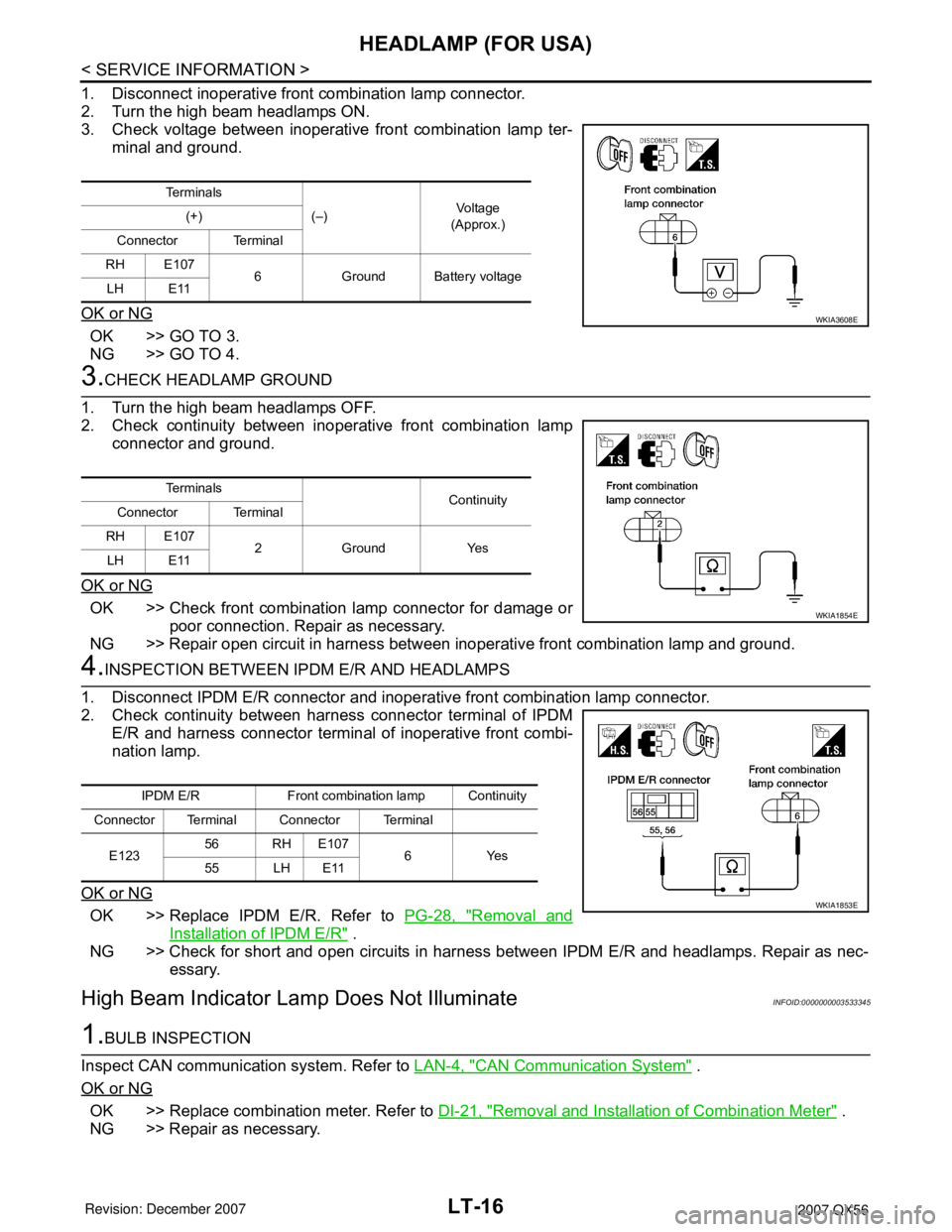
1. Disconnect inoperative front combination lamp connector.
2. Turn the high beam headlamps ON.
3. Check voltage between inoperative front combination lamp ter-
minal and ground.
OK or NG
OK >> GO TO 3.
NG >> GO TO 4.
3.CHECK HEADLAMP GROUND
1. Turn the high beam headlamps OFF.
2. Check continuity between inoperative front combination lamp
connector and ground.
OK or NG
OK >> Check front combination lamp connector for damage or
poor connection. Repair as necessary.
NG >> Repair open circuit in harness between inoperative front combination lamp and ground.
4.INSPECTION BETWEEN IPDM E/R AND HEADLAMPS
1. Disconnect IPDM E/R connector and inoperative front combination lamp connector.
2. Check continuity between harness connector terminal of IPDM
E/R and harness connector terminal of inoperative front combi-
nation lamp.
OK or NG
OK >> Replace IPDM E/R. Refer to PG-28, "Removal and
Installation of IPDM E/R" .
NG >> Check for short and open circuits in harness between IPDM E/R and headlamps. Repair as nec-
essary.
High Beam Indicator Lamp Does Not IlluminateINFOID:0000000003533345
1.BULB INSPECTION
Inspect CAN communication system. Refer to LAN-4, "
CAN Communication System" .
OK or NG
OK >> Replace combination meter. Refer to DI-21, "Removal and Installation of Combination Meter" .
NG >> Repair as necessary.
Te r m i n a l s
(–)Vo l ta g e
(Approx.) (+)
Connector Terminal
RH E107
6 Ground Battery voltage
LH E11
WKIA3608E
Te r m i n a l s
Continuity
Connector Terminal
RH E107
2 Ground Yes
LH E11
WKIA1854E
IPDM E/R Front combination lamp Continuity
Connector Terminal Connector Terminal
E12356 RH E107
6Yes
55 LH E11
WKIA1853E
Page 2224 of 3061
HEADLAMP (FOR USA)
LT-17
< SERVICE INFORMATION >
C
D
E
F
G
H
I
J
L
MA
B
LT
N
O
P
Headlamp LO Does Not Illuminate (Both Sides)INFOID:0000000003533346
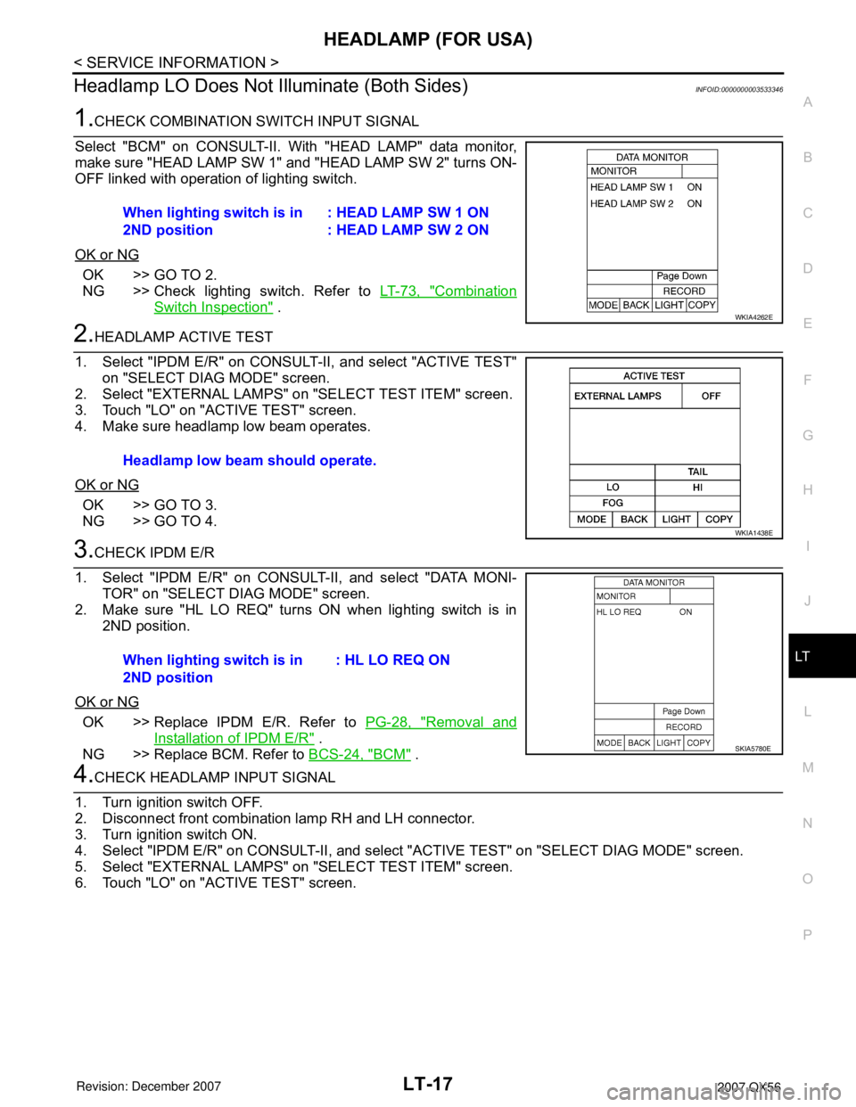
1.CHECK COMBINATION SWITCH INPUT SIGNAL
Select "BCM" on CONSULT-II. With "HEAD LAMP" data monitor,
make sure "HEAD LAMP SW 1" and "HEAD LAMP SW 2" turns ON-
OFF linked with operation of lighting switch.
OK or NG
OK >> GO TO 2.
NG >> Check lighting switch. Refer to LT-73, "
Combination
Switch Inspection" .
2.HEADLAMP ACTIVE TEST
1. Select "IPDM E/R" on CONSULT-II, and select "ACTIVE TEST"
on "SELECT DIAG MODE" screen.
2. Select "EXTERNAL LAMPS" on "SELECT TEST ITEM" screen.
3. Touch "LO" on "ACTIVE TEST" screen.
4. Make sure headlamp low beam operates.
OK or NG
OK >> GO TO 3.
NG >> GO TO 4.
3.CHECK IPDM E/R
1. Select "IPDM E/R" on CONSULT-II, and select "DATA MONI-
TOR" on "SELECT DIAG MODE" screen.
2. Make sure "HL LO REQ" turns ON when lighting switch is in
2ND position.
OK or NG
OK >> Replace IPDM E/R. Refer to PG-28, "Removal and
Installation of IPDM E/R" .
NG >> Replace BCM. Refer to BCS-24, "
BCM" .
4.CHECK HEADLAMP INPUT SIGNAL
1. Turn ignition switch OFF.
2. Disconnect front combination lamp RH and LH connector.
3. Turn ignition switch ON.
4. Select "IPDM E/R" on CONSULT-II, and select "ACTIVE TEST" on "SELECT DIAG MODE" screen.
5. Select "EXTERNAL LAMPS" on "SELECT TEST ITEM" screen.
6. Touch "LO" on "ACTIVE TEST" screen.When lighting switch is in
2ND position: HEAD LAMP SW 1 ON
: HEAD LAMP SW 2 ON
WKIA4262E
Headlamp low beam should operate.
WKIA1438E
When lighting switch is in
2ND position: HL LO REQ ON
SKIA5780E
Page 2225 of 3061
LT-18
< SERVICE INFORMATION >
HEADLAMP (FOR USA)
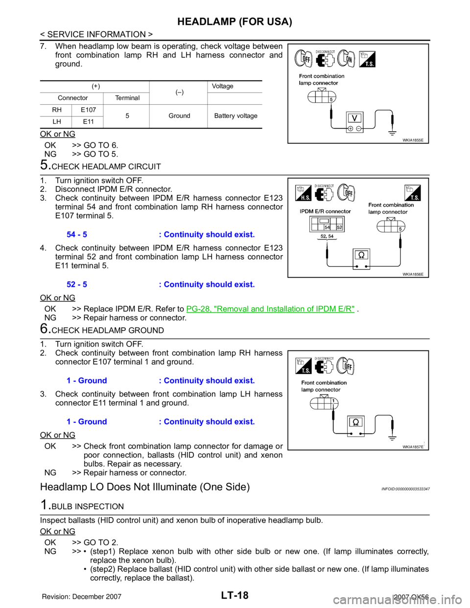
7. When headlamp low beam is operating, check voltage between
front combination lamp RH and LH harness connector and
ground.
OK or NG
OK >> GO TO 6.
NG >> GO TO 5.
5.CHECK HEADLAMP CIRCUIT
1. Turn ignition switch OFF.
2. Disconnect IPDM E/R connector.
3. Check continuity between IPDM E/R harness connector E123
terminal 54 and front combination lamp RH harness connector
E107 terminal 5.
4. Check continuity between IPDM E/R harness connector E123
terminal 52 and front combination lamp LH harness connector
E11 terminal 5.
OK or NG
OK >> Replace IPDM E/R. Refer to PG-28, "Removal and Installation of IPDM E/R" .
NG >> Repair harness or connector.
6.CHECK HEADLAMP GROUND
1. Turn ignition switch OFF.
2. Check continuity between front combination lamp RH harness
connector E107 terminal 1 and ground.
3. Check continuity between front combination lamp LH harness
connector E11 terminal 1 and ground.
OK or NG
OK >> Check front combination lamp connector for damage or
poor connection, ballasts (HID control unit) and xenon
bulbs. Repair as necessary.
NG >> Repair harness or connector.
Headlamp LO Does Not Illuminate (One Side)INFOID:0000000003533347
1.BULB INSPECTION
Inspect ballasts (HID control unit) and xenon bulb of inoperative headlamp bulb.
OK or NG
OK >> GO TO 2.
NG >> • (step1) Replace xenon bulb with other side bulb or new one. (If lamp illuminates correctly,
replace the xenon bulb).
• (step2) Replace ballast (HID control unit) with other side ballast or new one. (If lamp illuminates
correctly, replace the ballast).
(+)
(–)Vol tag e
Connector Terminal
RH E107
5 Ground Battery voltage
LH E11
WKIA1855E
54 - 5 : Continuity should exist.
52 - 5 : Continuity should exist.
WKIA1856E
1 - Ground : Continuity should exist.
1 - Ground : Continuity should exist.
WKIA1857E
Page 2226 of 3061
HEADLAMP (FOR USA)
LT-19
< SERVICE INFORMATION >
C
D
E
F
G
H
I
J
L
MA
B
LT
N
O
P
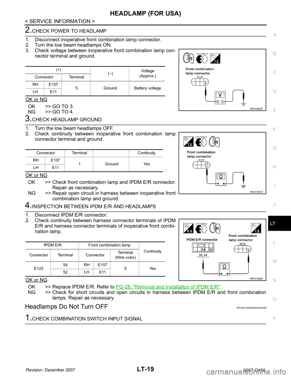
2.CHECK POWER TO HEADLAMP
1. Disconnect inoperative front combination lamp connector.
2. Turn the low beam headlamps ON.
3. Check voltage between inoperative front combination lamp con-
nector terminal and ground.
OK or NG
OK >> GO TO 3.
NG >> GO TO 4.
3.CHECK HEADLAMP GROUND
1. Turn the low beam headlamps OFF.
2. Check continuity between inoperative front combination lamp
connector terminal and ground.
OK or NG
OK >> Check front combination lamp and IPDM E/R connector.
Repair as necessary.
NG >> Repair open circuit in harness between inoperative front
combination lamp and ground.
4.INSPECTION BETWEEN IPDM E/R AND HEADLAMPS
1. Disconnect IPDM E/R connector.
2. Check continuity between harness connector terminals of IPDM
E/R and harness connector terminals of inoperative front combi-
nation lamp.
OK or NG
OK >> Replace IPDM E/R. Refer to PG-28, "Removal and Installation of IPDM E/R" .
NG >> Check for short circuits and open circuits in harness between IPDM E/R and front combination
lamps. Repair as necessary.
Headlamps Do Not Turn OFFINFOID:0000000003533348
1.CHECK COMBINATION SWITCH INPUT SIGNAL
(+)
(–)Vo l ta g e
(Approx.)
Connector Terminal
RH E107
5 Ground Battery voltage
LH E11
WKIA3609E
Connector Terminal Continuity
RH E107
1 Ground Yes
LH E11
WKIA1857E
IPDM E/R Front combination lamp
Continuity
Connector Terminal ConnectorTe r m i n a l
(Wire color)
E12354 RH E107
5Yes
52 LH E11
WKIA1856E
Page 2227 of 3061
LT-20
< SERVICE INFORMATION >
HEADLAMP (FOR USA)
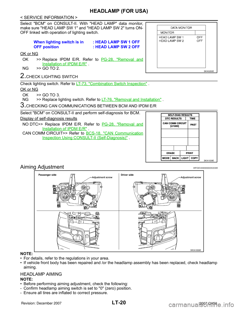
Select "BCM" on CONSULT-II. With "HEAD LAMP" data monitor,
make sure "HEAD LAMP SW 1" and "HEAD LAMP SW 2" turns ON-
OFF linked with operation of lighting switch.
OK or NG
OK >> Replace IPDM E/R. Refer to PG-28, "Removal and
Installation of IPDM E/R" .
NG >> GO TO 2.
2.CHECK LIGHTING SWITCH
Check lighting switch. Refer to LT-73, "
Combination Switch Inspection" .
OK or NG
OK >> GO TO 3.
NG >> Replace lighting switch. Refer to LT-76, "
Removal and Installation" .
3.CHECKING CAN COMMUNICATIONS BETWEEN BCM AND IPDM E/R
Select "BCM" on CONSULT-II and perform self-diagnosis for BCM.
Display of self-diagnosis results
NO DTC>> Replace IPDM E/R. Refer to PG-28, "Removal and
Installation of IPDM E/R" .
CAN COMM CIRCUIT>> Refer to BCS-18, "
CAN Communication
Inspection Using CONSULT-II (Self-Diagnosis)" .
Aiming AdjustmentINFOID:0000000003533349
NOTE:
• For details, refer to the regulations in your area.
• If vehicle front body has been repaired and /or the headlamp assembly has been replaced, check headlamp
aiming.
HEADLAMP AIMING
NOTE:
• Before performing aiming adjustment, check the following:
- Confirm headlamp aiming switch is set to "0" (zero) position.
- Ensure all tires are inflated to correct pressure.When lighting switch is in
OFF position: HEAD LAMP SW 1 OFF
: HEAD LAMP SW 2 OFF
SKIA5200E
SKIA1039E
WKIA1859E