Page 2212 of 3061

HEADLAMP (FOR USA)
LT-5
< SERVICE INFORMATION >
C
D
E
F
G
H
I
J
L
MA
B
LT
N
O
P
HEADLAMP (FOR USA)
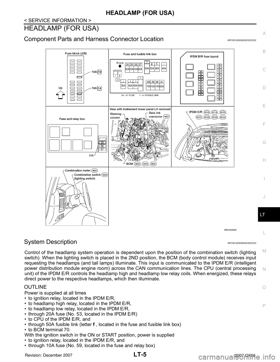
Component Parts and Harness Connector LocationINFOID:0000000003533332
System DescriptionINFOID:0000000003533333
Control of the headlamp system operation is dependent upon the position of the combination switch (lighting
switch). When the lighting switch is placed in the 2ND position, the BCM (body control module) receives input
requesting the headlamps (and tail lamps) illuminate. This input is communicated to the IPDM E/R (intelligent
power distribution module engine room) across the CAN communication lines. The CPU (central processing
unit) of the IPDM E/R controls the headlamp high and headlamp low relay coils. When energized, these relays
direct power to the respective headlamps, which then illuminate.
OUTLINE
Power is supplied at all times
• to ignition relay, located in the IPDM E/R,
• to headlamp high relay, located in the IPDM E/R,
• to headlamp low relay, located in the IPDM E/R,
• through 20A fuse (No. 53, located in the IPDM E/R)
• to CPU of the IPDM E/R, and
• through 50A fusible link (letter f , located in the fuse and fusible link box)
• to BCM terminal 70.
With the ignition switch in the ON or START position, power is supplied
• to ignition relay, located in the IPDM E/R, and
• through 10A fuse (No. 59, located in the fuse and relay box)
WKIA3463E
Page 2213 of 3061

LT-6
< SERVICE INFORMATION >
HEADLAMP (FOR USA)
• to BCM terminal 38.
Ground is supplied
• to BCM terminal 67
• through grounds M57, M61 and M79, and
• to IPDM E/R terminals 38 and 59
• through grounds E9, E15 and E24.
Low Beam Operation
With the lighting switch in 2ND position, the BCM receives input requesting the headlamps to illuminate. This
input is communicated to the IPDM E/R across the CAN communication lines. The CPU of the IPDM E/R con-
trols the headlamp low relay coil. When energized, this relay directs power
• through 15A fuse (No. 41, located in the IPDM E/R)
• through IPDM E/R terminal 54
• to front combination lamp RH terminal 5, and
• through 15A fuse (No. 40, located in the IPDM E/R)
• through IPDM E/R terminal 52
• to front combination lamp LH terminal 5.
Ground is supplied
• to front combination lamp LH and RH terminal 1
• through grounds E9, E15 and E24.
With power and ground supplied, low beam headlamps illuminate.
High Beam Operation/Flash-to-Pass Operation
With the lighting switch in 2ND position and placed in HIGH or PASS position, the BCM receives input request-
ing the headlamp high beams to illuminate. This input is communicated to the IPDM E/R across the CAN com-
munication lines. The CPU of the combination meter controls the ON/OFF status of the HIGH BEAM indicator.
The CPU of the IPDM E/R controls the headlamp high relay coil. When energized, this relay directs power
• through 10A fuse (No. 34, located in the IPDM E/R)
• through IPDM E/R terminal 56
• to front combination lamp RH terminal 6, and
• through 10A fuse (No. 35, located in the IPDM E/R)
• through IPDM E/R terminal 55
• to front combination lamp LH terminal 6.
Ground is supplied
• to front combination lamp LH and RH terminal 2
• through grounds E9, E15 and E24.
With power and ground supplied, the high beam headlamps illuminate.
XENON HEADLAMP
Xenon type headlamp is adopted to the low beam headlamps. Xenon bulbs do not use a filament. Instead,
they produce light when a high voltage current is passed between two tungsten electrodes through a mixture
of xenon (an inert gas) and certain other metal halides. In addition to added lighting power, electronic control
of the power supply gives the headlamps stable quality and tone color.
Following are some of the many advantages of the xenon type headlamp.
• The light produced by the headlamps is a white color comparable to sunlight that is easy on the eyes.
• Light output is nearly double that of halogen headlamps, affording increased area of illumination.
• The light features a high relative spectral distribution at wavelengths to which the human eye is most sensi-
tive. This means that even in the rain, more light is reflected back from the road surface toward the vehicle,
for added visibility.
• Power consumption is approximately 25 percent less than halogen headlamps, reducing battery load.
BATTERY SAVER CONTROL
When the combination switch (lighting switch) is in the 2ND position (ON), and the ignition switch is turned
from ON or ACC to OFF, the battery saver control feature is activated.
Under this condition, the headlamps remain illuminated for 5 minutes, unless the combination switch (lighting
switch) position is changed. If the combination switch (lighting switch) position is changed, then the headlamps
are turned off.
AUTO LIGHT OPERATION
Refer to LT-34, "System Description" for auto light operation.
VEHICLE SECURITY SYSTEM (PANIC ALARM)
Page 2214 of 3061
HEADLAMP (FOR USA)
LT-7
< SERVICE INFORMATION >
C
D
E
F
G
H
I
J
L
MA
B
LT
N
O
P
The vehicle security system (panic alarm) will flash the high beams if the system is triggered. Refer to BL-61,
"System Description".
CAN Communication System DescriptionINFOID:0000000003533334
Refer to LAN-4, "CAN Communication System".
SchematicINFOID:0000000003533335
WKWA3637E
Page 2215 of 3061
LT-8
< SERVICE INFORMATION >
HEADLAMP (FOR USA)
Wiring Diagram - H/LAMP -
INFOID:0000000003533336
WKWA3638E
Page 2216 of 3061
HEADLAMP (FOR USA)
LT-9
< SERVICE INFORMATION >
C
D
E
F
G
H
I
J
L
MA
B
LT
N
O
P
WKWA3639E
Page 2217 of 3061
LT-10
< SERVICE INFORMATION >
HEADLAMP (FOR USA)
WKWA2482E
Page 2218 of 3061
HEADLAMP (FOR USA)
LT-11
< SERVICE INFORMATION >
C
D
E
F
G
H
I
J
L
MA
B
LT
N
O
P
Terminal and Reference Value for BCMINFOID:0000000003533337
Refer to BCS-11, "Terminal and Reference Value for BCM".
Terminal and Reference Value for IPDM E/RINFOID:0000000003533338
Refer to PG-22, "Terminal and Reference Value for IPDM E/R".
WKWA3640E
Page 2219 of 3061

LT-12
< SERVICE INFORMATION >
HEADLAMP (FOR USA)
How to Proceed with Trouble Diagnosis
INFOID:0000000003533339
1. Confirm the symptom or customer complaint.
2. Understand operation description and function description. Refer to LT- 5 , "
System Description" .
3. Perform the Preliminary Check.
4. Check symptom and repair or replace the component.
5. Does the headlamp operate normally? If YES: GO TO 6. If NO: GO TO 4.
6. Inspection End.
Preliminary CheckINFOID:0000000003533340
CHECK POWER SUPPLY AND GROUND CIRCUIT FOR BCM
Refer to BCS-15, "BCM Power Supply and Ground Circuit Inspection" .
CHECK POWER SUPPLY AND GROUND CIRCUIT FOR IPDM E/R
Refer to PG-26, "IPDM E/R Power/Ground Circuit Inspection" .
CONSULT-II Function (BCM)INFOID:0000000003533341
Refer to BCS-16, "CONSULT-II Function (BCM)" .
CONSULT-II START PROCEDURE
Refer to GI-36, "CONSULT-II Start Procedure" .
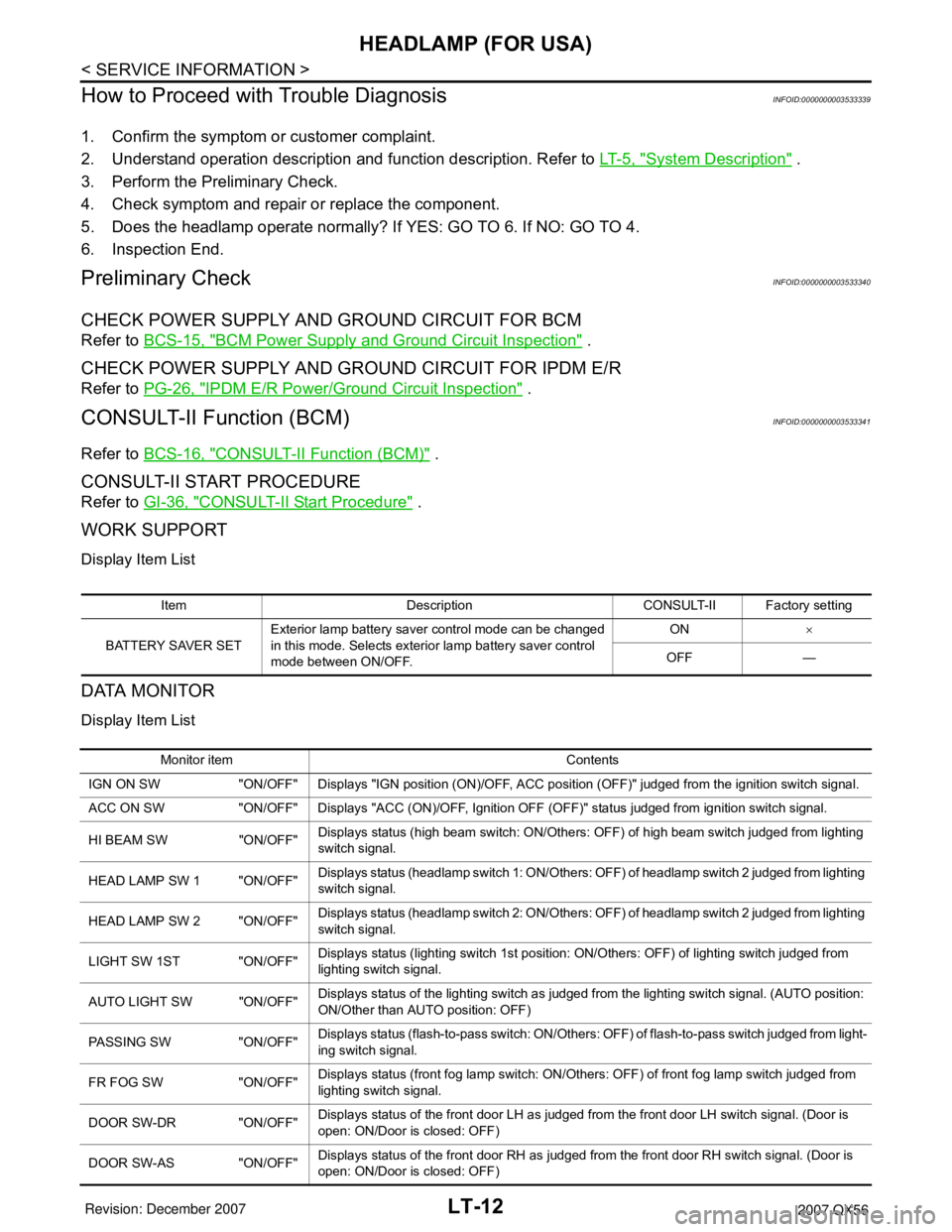
WORK SUPPORT
Display Item List
DATA MONITOR
Display Item List
Item Description CONSULT-II Factory setting
BATTERY SAVER SETExterior lamp battery saver control mode can be changed
in this mode. Selects exterior lamp battery saver control
mode between ON/OFF.ON×
OFF —
Monitor item Contents
IGN ON SW "ON/OFF" Displays "IGN position (ON)/OFF, ACC position (OFF)" judged from the ignition switch signal.
ACC ON SW "ON/OFF" Displays "ACC (ON)/OFF, Ignition OFF (OFF)" status judged from ignition switch signal.
HI BEAM SW "ON/OFF"Displays status (high beam switch: ON/Others: OFF) of high beam switch judged from lighting
switch signal.
HEAD LAMP SW 1 "ON/OFF"Displays status (headlamp switch 1: ON/Others: OFF) of headlamp switch 2 judged from lighting
switch signal.
HEAD LAMP SW 2 "ON/OFF"Displays status (headlamp switch 2: ON/Others: OFF) of headlamp switch 2 judged from lighting
switch signal.
LIGHT SW 1ST "ON/OFF"Displays status (lighting switch 1st position: ON/Others: OFF) of lighting switch judged from
lighting switch signal.
AUTO LIGHT SW "ON/OFF"Displays status of the lighting switch as judged from the lighting switch signal. (AUTO position:
ON/Other than AUTO position: OFF)
PASSING SW "ON/OFF"Displays status (flash-to-pass switch: ON/Others: OFF) of flash-to-pass switch judged from light-
ing switch signal.
FR FOG SW "ON/OFF"Displays status (front fog lamp switch: ON/Others: OFF) of front fog lamp switch judged from
lighting switch signal.
DOOR SW-DR "ON/OFF"Displays status of the front door LH as judged from the front door LH switch signal. (Door is
open: ON/Door is closed: OFF)
DOOR SW-AS "ON/OFF"Displays status of the front door RH as judged from the front door RH switch signal. (Door is
open: ON/Door is closed: OFF)