2007 INFINITI QX56 steering wheel
[x] Cancel search: steering wheelPage 1960 of 3061
FSU-14
< SERVICE INFORMATION >
LOWER LINK
LOWER LINK
Removal and InstallationINFOID:0000000003532642
REMOVAL
1. Remove the wheel and tire using power tool.
2. Remove lower shock absorber bolt.
3. Remove stabilizer bar connecting rod lower nut using power tool, then separate connecting rod from lower
link. Refer to FSU-12, "
Removal and Installation".
4. Remove drive shaft nut, if equipped. Refer to FA X - 7 , "
Removal and Installation".
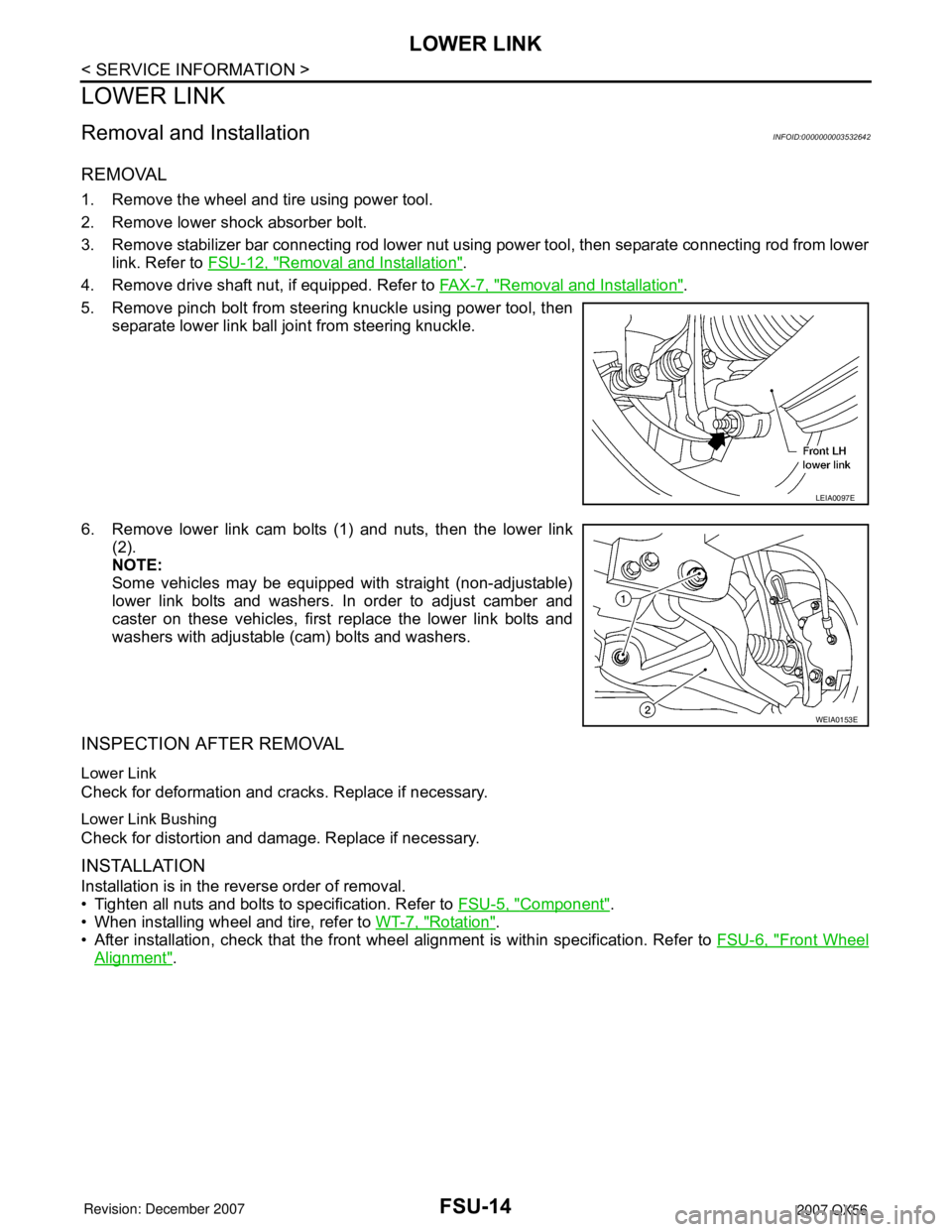
5. Remove pinch bolt from steering knuckle using power tool, then
separate lower link ball joint from steering knuckle.
6. Remove lower link cam bolts (1) and nuts, then the lower link
(2).
NOTE:
Some vehicles may be equipped with straight (non-adjustable)
lower link bolts and washers. In order to adjust camber and
caster on these vehicles, first replace the lower link bolts and
washers with adjustable (cam) bolts and washers.
INSPECTION AFTER REMOVAL
Lower Link
Check for deformation and cracks. Replace if necessary.
Lower Link Bushing
Check for distortion and damage. Replace if necessary.
INSTALLATION
Installation is in the reverse order of removal.
• Tighten all nuts and bolts to specification. Refer to FSU-5, "
Component".
• When installing wheel and tire, refer to WT-7, "
Rotation".
• After installation, check that the front wheel alignment is within specification. Refer to FSU-6, "
Front Wheel
Alignment".
LEIA0097E
WEIA0153E
Page 1963 of 3061
KNUCKLE
FSU-17
< SERVICE INFORMATION >
C
D
F
G
H
I
J
K
L
MA
B
FSU
N
O
P
KNUCKLE
On-Vehicle Inspection and ServiceINFOID:0000000003532645
Make sure the mounting conditions (looseness, backlash) of each component and component status (wear,
damage) are within specifications. Refer to FSU-20, "
Ball Joint" .
Removal and InstallationINFOID:0000000003532646
REMOVAL
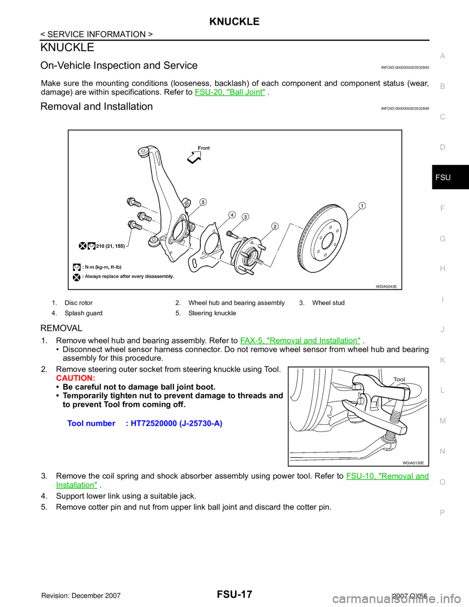
1. Remove wheel hub and bearing assembly. Refer to FAX-5, "Removal and Installation" .
• Disconnect wheel sensor harness connector. Do not remove wheel sensor from wheel hub and bearing
assembly for this procedure.
2. Remove steering outer socket from steering knuckle using Tool.
CAUTION:
• Be careful not to damage ball joint boot.
• Temporarily tighten nut to prevent damage to threads and
to prevent Tool from coming off.
3. Remove the coil spring and shock absorber assembly using power tool. Refer to FSU-10, "
Removal and
Installation" .
4. Support lower link using a suitable jack.
5. Remove cotter pin and nut from upper link ball joint and discard the cotter pin.
1. Disc rotor 2. Wheel hub and bearing assembly 3. Wheel stud
4. Splash guard 5. Steering knuckle
WDIA0043E
Tool number : HT72520000 (J-25730-A)
WGIA0130E
Page 1964 of 3061
FSU-18
< SERVICE INFORMATION >
KNUCKLE
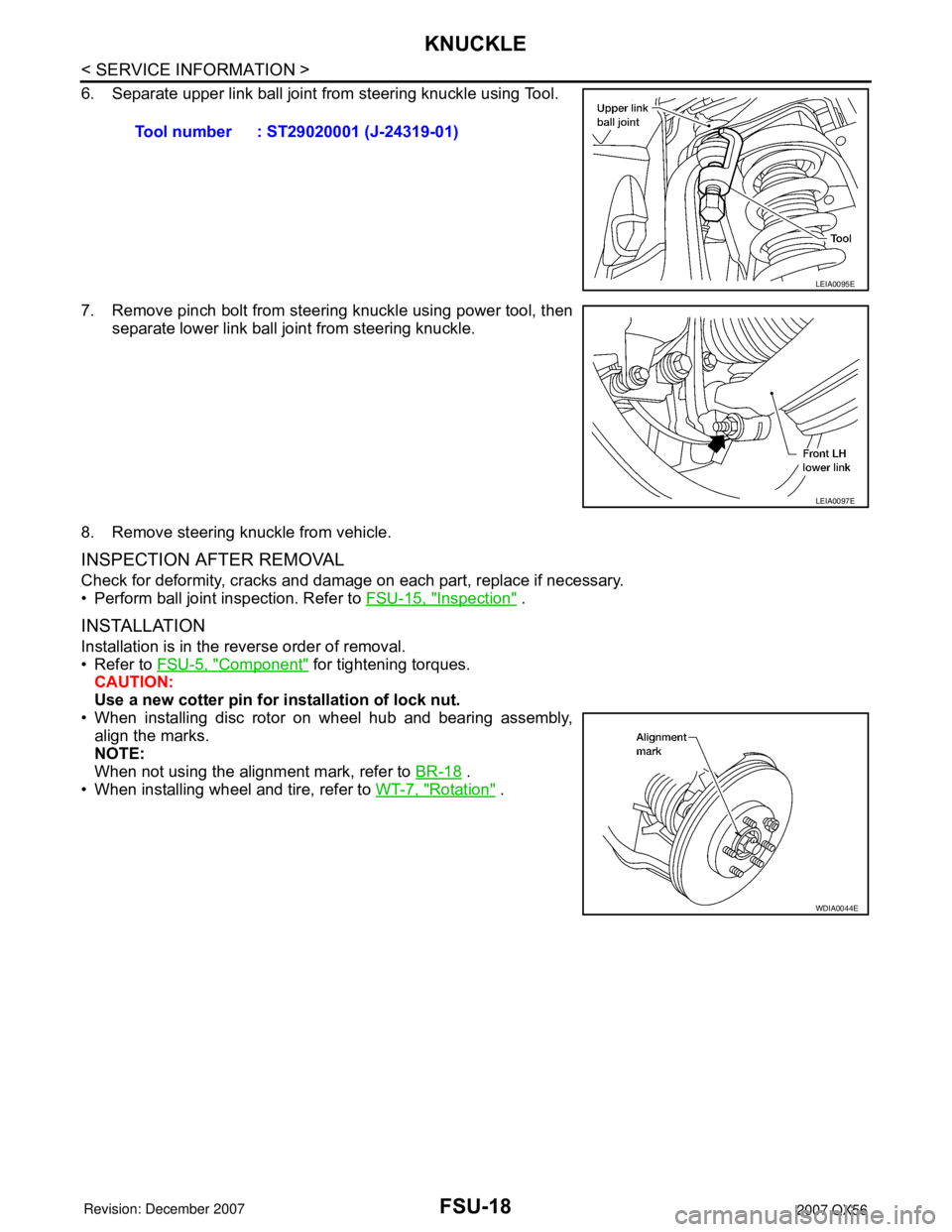
6. Separate upper link ball joint from steering knuckle using Tool.
7. Remove pinch bolt from steering knuckle using power tool, then
separate lower link ball joint from steering knuckle.
8. Remove steering knuckle from vehicle.
INSPECTION AFTER REMOVAL
Check for deformity, cracks and damage on each part, replace if necessary.
• Perform ball joint inspection. Refer to FSU-15, "
Inspection" .
INSTALLATION
Installation is in the reverse order of removal.
• Refer to FSU-5, "
Component" for tightening torques.
CAUTION:
Use a new cotter pin for installation of lock nut.
• When installing disc rotor on wheel hub and bearing assembly,
align the marks.
NOTE:
When not using the alignment mark, refer to BR-18
.
• When installing wheel and tire, refer to WT-7, "
Rotation" . Tool number : ST29020001 (J-24319-01)
LEIA0095E
LEIA0097E
WDIA0044E
Page 1987 of 3061
HOW TO USE THIS MANUAL
GI-21
< SERVICE INFORMATION >
C
D
E
F
G
H
I
J
K
L
MB
GI
N
O
PLH, RH Left-Hand, Right-Hand
M/T Manual Transaxle/Transmission
OD Overdrive
P/S Power Steering
SAE Society of Automotive Engineers, Inc.
SDS Service Data and Specifications
SST Special Service Tools
2WD 2-Wheel Drive
2
22nd range 2nd gear
2
12nd range 1st gear
1
21st range 2nd gear
1
11st range 1st gear ABBREVIATION DESCRIPTION
Page 2008 of 3061
GI-42
< SERVICE INFORMATION >
TOW TRUCK TOWING
TOW TRUCK TOWING
Tow Truck TowingINFOID:0000000003531499
WARNING:
• Never get under the vehicle while it is supported only by the jack. Always use safety stands to sup-
port the frame when you have to get under the vehicle.
• Place wheel chocks at both front and back of the wheels on the ground.
CAUTION:
• All applicable State or Provincial (in Canada) laws and local laws regarding the towing operation
must be obeyed.
• It is necessary to use proper towing equipment to avoid possible damage during towing operation.
Towing is in accordance with Towing Procedure Manual at dealer.
• Always attach safety chains before towing.
• When towing, make sure that the transmission, steering system and powertrain are in good order. If
any unit is damaged, dollies must be used.
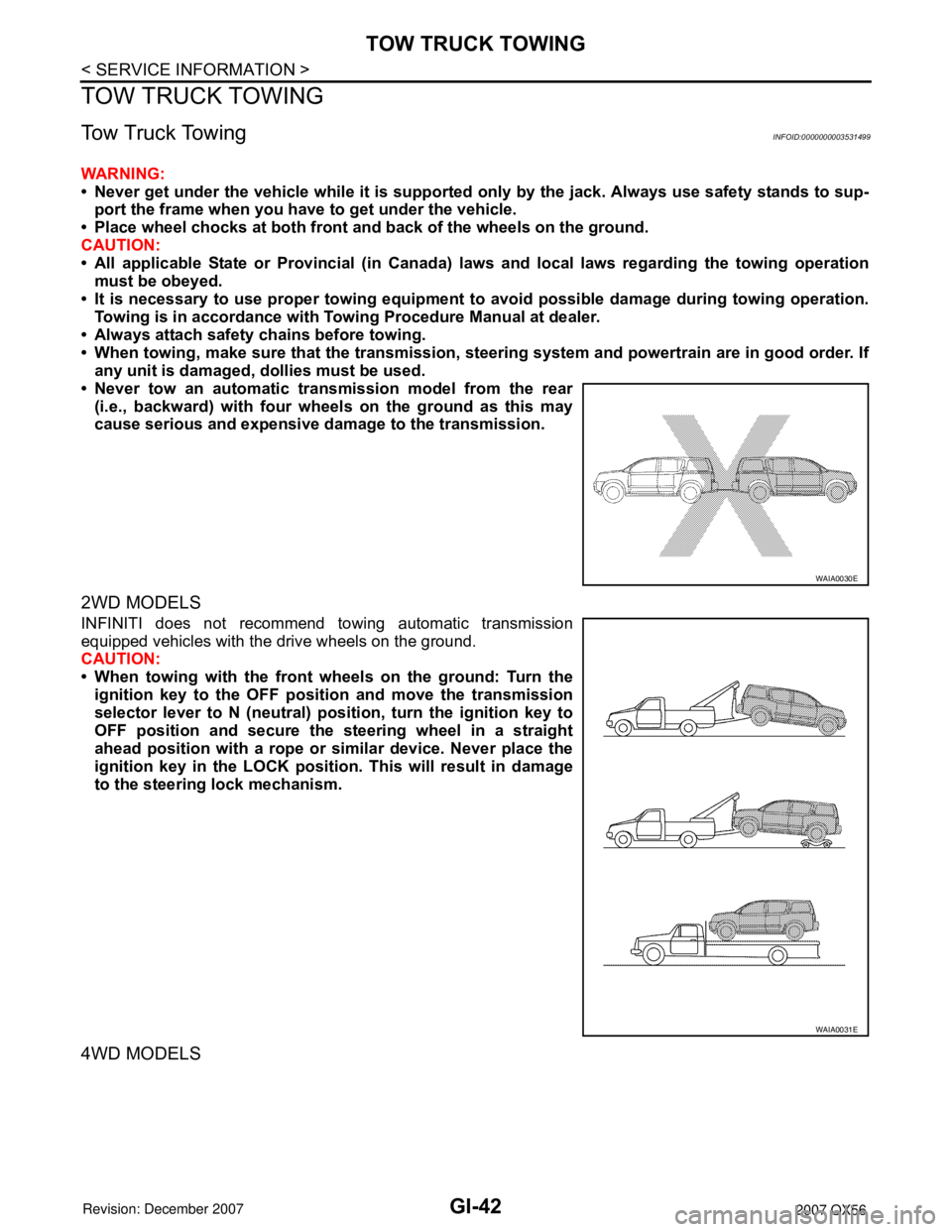
• Never tow an automatic transmission model from the rear
(i.e., backward) with four wheels on the ground as this may
cause serious and expensive damage to the transmission.
2WD MODELS
INFINITI does not recommend towing automatic transmission
equipped vehicles with the drive wheels on the ground.
CAUTION:
• When towing with the front wheels on the ground: Turn the
ignition key to the OFF position and move the transmission
selector lever to N (neutral) position, turn the ignition key to
OFF position and secure the steering wheel in a straight
ahead position with a rope or similar device. Never place the
ignition key in the LOCK position. This will result in damage
to the steering lock mechanism.
4WD MODELS
WAIA0030E
WAIA0031E
Page 2009 of 3061
TOW TRUCK TOWING
GI-43
< SERVICE INFORMATION >
C
D
E
F
G
H
I
J
K
L
MB
GI
N
O
P
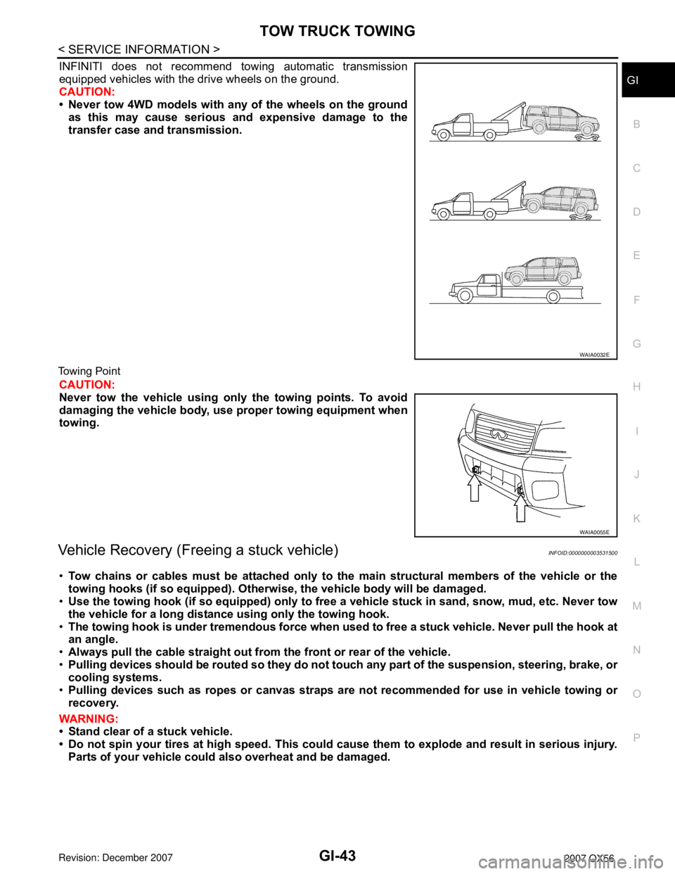
INFINITI does not recommend towing automatic transmission
equipped vehicles with the drive wheels on the ground.
CAUTION:
• Never tow 4WD models with any of the wheels on the ground
as this may cause serious and expensive damage to the
transfer case and transmission.
Towing Point
CAUTION:
Never tow the vehicle using only the towing points. To avoid
damaging the vehicle body, use proper towing equipment when
towing.
Vehicle Recovery (Freeing a stuck vehicle)INFOID:0000000003531500
•Tow chains or cables must be attached only to the main structural members of the vehicle or the
towing hooks (if so equipped). Otherwise, the vehicle body will be damaged.
•Use the towing hook (if so equipped) only to free a vehicle stuck in sand, snow, mud, etc. Never tow
the vehicle for a long distance using only the towing hook.
•The towing hook is under tremendous force when used to free a stuck vehicle. Never pull the hook at
an angle.
•Always pull the cable straight out from the front or rear of the vehicle.
•Pulling devices should be routed so they do not touch any part of the suspension, steering, brake, or
cooling systems.
•Pulling devices such as ropes or canvas straps are not recommended for use in vehicle towing or
recovery.
WARNING:
• Stand clear of a stuck vehicle.
• Do not spin your tires at high speed. This could cause them to explode and result in serious injury.
Parts of your vehicle could also overheat and be damaged.
WAIA0032E
WAIA0055E
Page 2111 of 3061
IDX-7
A
C
D
E
F
G
H
I
J
K
L B
IDX
ALPHABETICAL INDEX
Pressure switch 2 ............................................. AT-153
Pressure switch 3 ............................... AT-137, AT-157
Pressure switch 5 ............................... AT-145, AT-159
Pressure switch 6 ............................... AT-149, AT-161
Pressure test (A/T) ............................................. AT-52
Propeller shaft ........................................... PR-4, PR-8
Propeller shaft inspection .................................. MA-25
Propeller shaft on vehicle service ....................... PR-8
Propeller shaft vibration ............................ PR-4, PR-8
PS/SEN - Wiring diagram ................................ EC-471
R
R/VIEW - Wiring diagram .................................... DI-66
Radiator ............................................................. CO-14
Rear Audio Remote Control Unit ......................... AV-8
Rear axle ........................................................... RAX-5
Rear bumper ....................................................... EI-15
Rear case (Transfer) .......................... TF-148, TF-181
Rear combination lamp removal and installation ... LT-
101
Rear cover packing replacement diff. .............. RFD-28
Rear door ........................................... BL-117, GW-65
Rear seat belt ...................................................... SB-7
Rear suspension ............................................. RSU-23
Rear view monitor ............................................... DI-63
Rear washer .................................................... WW-29
Rear window defogger ..................................... GW-71
Rear wiper ....................................................... WW-29
Refrigerant connection precaution .................... ATC-6
Refrigerant discharging evacuating charging ATC-175
Refrigerant general precaution .......................... ATC-6
Refrigerant lines ........... ATC-175, ATC-183, ATC-184
Refrigerant pressure sensor ............ EC-692, ATC-184
Relay box .......................................................... PG-78
Remote keyless entry system ............................ BL-40
Removal and installation (A/T) ........... AT-238, AT-241
Removal and installation (Transfer) ................. TF-145
Ring gear diff. inspection ................................. RFD-18
Road wheel size ................................................. GI-51
Rocker cover ..................................................... EM-35
Room lamp ....................................................... LT-110
Room lamp - See Interior lamp ........................ LT-110
ROOM/L - Wiring diagram ................................ LT-116
RP/SEN - Wiring diagram ............................... EC-693
S
SAE J1979 - Service $01 - 09 ........................... EC-49
SEAT - Wiring diagram ..................................... SE-81
Seat belt inspection ............................... SB-12, MA-32
Seat belt pre-tensioner .................................... SRS-50
Seat belt, front ..................................................... SB-3
Seat belt, rear ...................................................... SB-7
Seat, front .......................................................... SE-89
Self-diagnosis (Transfer) .................................... TF-49
SEN/PW - Wiring diagram ............................... EC-483
SHIFT - Wiring diagram ................................... AT-217
Shift control (Transfer) ....................... TF-149, TF-176
Shift lock system .............................................. AT-216
Shock absorber (front) ..................................... FSU-11
Shock absorber (rear) ..................................... RSU-32
Side air bag (satellite) sensor .......................... SRS-49
Side curtain air bag .......................................... SRS-46
Side trim .............................................................. EI-35
SMJ (super multiple junction) ............................ PG-74
SONAR - Wiring diagram ................................... DI-53
Spare tire size ..................................................... GI-51
Spark plug ......................................................... EM-29
Specification value ........................................... EC-139
Speedometer ........................................................ DI-5
Spiral cable ...................................................... SRS-41
SROOF - Wiring diagram .................................. RF-13
SRS - See Supplemental Restraint System ...... SRS-5
SRS - Wiring diagram ...................................... SRS-13
SRS Trouble diagnoses ..................................... SRS-9
Stabilizer bar (front) ......................................... FSU-12
Stabilizer bar (rear) ......................................... RSU-39
Stall test (A/T) .................................................... AT-51
Standardized relay ............................................. PG-72
START - Wiring diagram ................................... SC-11
Starting system .................................................. SC-10
Steering gear, linkage and transfer gear inspection .....
MA-29
Steering linkage ................................................. PS-15
Steering wheel and column ................................. PS-7
Step lamp ......................................................... LT-111
Stop lamp ........................................................... LT-84
Stop lamp switch ................. EC-572, EC-584, EC-647
STOP/L - Wiring diagram ................................... LT-85
Strut (front) ...................................................... FSU-10
STSIG - Wiring diagram .................................... AT-97
Sub-oil pump (Transfer) ...................... TF-154, TF-167
Sun gear (Transfer) ............................ TF-149, TF-176
Sun roof, electric ................................................ RF-10
Sunload sensor .............................................. ATC-144
Sunroof .............................................................. RF-22
Supplemental Restraint System ........................ SRS-5
Supplemental restraint system - Wiring diagram . SRS-
13
Symbols and abbreviations ..................... GI-10, GI-23
Symptom matrix chart ........................................ EC-94
System readiness test (SRT) code .................... EC-55
T
Tachometer .......................................................... DI-5
Tail lamp ............................................................. LT-89
TAIL/L - Wiring diagram ...................................... LT-91
TCM circuit diagram .......................................... AT-50
TCS - Wiring diagram ..................................... BRC-16
TCS (traction control system) ........................... BRC-7
TCS component parts and connector location BRC-14
TCS wheel sensors ........................................ BRC-14
Telephone .......................................................... AV-62
Theft warning system - See Vehicle security (Theft warn-
ing) system ......................................................... BL-67
Thermometer ...................................................... DI-23
Page 2363 of 3061
MA-1
MAINTENANCE
C
D
E
F
G
H
I
J
K
M
SECTION MA
A
B
MA
N
O
P
CONTENTS
MAINTENANCE
SERVICE INFORMATION ............................2
PRECAUTIONS ...................................................2
Precaution for Supplemental Restraint System
(SRS) "AIR BAG" and "SEAT BELT PRE-TEN-
SIONER" ...................................................................
2
PREPARATION ...................................................3
Special Service Tool .................................................3
Commercial Service Tool ..........................................3
GENERAL MAINTENANCE ................................4
General Maintenance ................................................4
PERIODIC MAINTENANCE ................................6
Introduction of Periodic Maintenance ........................6
Maintenance for Off-road Driving (4WD only) ...........6
Schedule 1 ................................................................6
Schedule 2 ................................................................8
RECOMMENDED FLUIDS AND LUBRI-
CANTS ................................................................
10
Fluids and Lubricants ..............................................10
SAE Viscosity Number ............................................10
ENGINE MAINTENANCE ...................................12
Checking Drive Belts ...............................................12
Changing Engine Coolant .......................................12
Checking Fuel Line .................................................15
Changing Fuel Filter ................................................15
Changing Engine Air Cleaner Filter .........................15
Changing Engine Oil ................................................16
Changing Oil Filter ...................................................16
Changing Spark Plugs .............................................18
Checking EVAP Vapor Line .....................................19
CHASSIS AND BODY MAINTENANCE ...........20
Changing In-cabin Microfilter ...................................20
Checking Exhaust System .......................................21
Checking Automatic Transmission Fluid (ATF) .......21
Changing Automatic Transmission Fluid (ATF) .......23
Changing Transfer Fluid ..........................................23
Checking Transfer Fluid ..........................................24
Checking Propeller Shaft .........................................24
Checking Final Drive Oil ..........................................24
Changing Final Drive Oil ..........................................25
Balancing Wheels ....................................................25
Tire Rotation ............................................................27
Checking Brake Fluid Level and Leaks ...................27
CheckingBrake Line and Cables .............................27
Checking Disc Brake ...............................................27
Checking Steering Gear and Linkage ......................28
Checking Power Steering Fluid and Line ................28
Checking Axle and Suspension Parts .....................29
Lubricating Locks, Hinges and Hood Latches .........30
Checking Seat Belts, Buckles, Retractors, An-
chors and Adjusters .................................................
30