2007 INFINITI QX56 checking oil
[x] Cancel search: checking oilPage 1906 of 3061
DIFFERENTIAL GEAR OIL
FFD-7
< SERVICE INFORMATION >
C
E
F
G
H
I
J
K
L
MA
B
FFD
N
O
P
DIFFERENTIAL GEAR OIL
Changing Differential Gear OilINFOID:0000000003532588
DRAINING
1. Stop the engine.
2. Remove the drain plug from the front final drive assembly to drain the differential gear oil.
3. Install the drain plug with sealant applied on the threads to the front final drive assembly. Tighten to the
specified torque. Refer to FFD-13, "
Disassembly and Assembly".
• Use High Performance Thread Sealant or equivalent. Refer to GI-45, "
Recommended Chemical Product
and Sealant".
FILLING
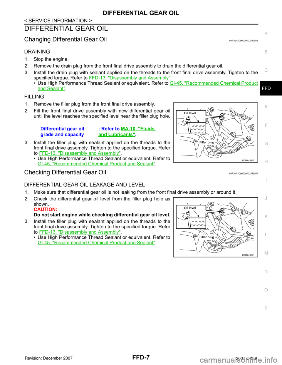
1. Remove the filler plug from the front final drive assembly.
2. Fill the front final drive assembly with new differential gear oil
until the level reaches the specified level near the filler plug hole.
3. Install the filler plug with sealant applied on the threads to the
front final drive assembly. Tighten to the specified torque. Refer
to FFD-13, "
Disassembly and Assembly".
• Use High Performance Thread Sealant or equivalent. Refer to
GI-45, "
Recommended Chemical Product and Sealant".
Checking Differential Gear OilINFOID:0000000003532589
DIFFERENTIAL GEAR OIL LEAKAGE AND LEVEL
1. Make sure that differential gear oil is not leaking from the front final drive assembly or around it.
2. Check the differential gear oil level from the filler plug hole as
shown.
CAUTION:
Do not start engine while checking differential gear oil level.
3. Install the filler plug with sealant applied on the threads to the
front final drive assembly. Tighten to the specified torque. Refer
to FFD-13, "
Disassembly and Assembly".
• Use High Performance Thread Sealant or equivalent. Refer to
GI-45, "
Recommended Chemical Product and Sealant". Differential gear oil
grade and capacity: Refer to MA-10, "
Fluids
and Lubricants".
LDIA0176E
LDIA0176E
Page 1916 of 3061
FRONT FINAL DRIVE ASSEMBLY
FFD-17
< SERVICE INFORMATION >
C
E
F
G
H
I
J
K
L
MA
B
FFD
N
O
P Backlash
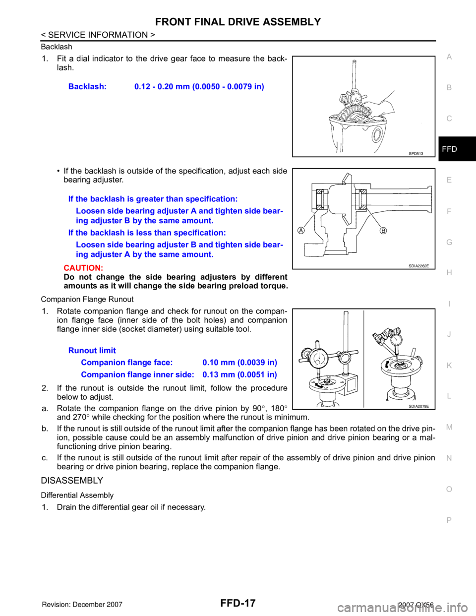
1. Fit a dial indicator to the drive gear face to measure the back-
lash.
• If the backlash is outside of the specification, adjust each side
bearing adjuster.
CAUTION:
Do not change the side bearing adjusters by different
amounts as it will change the side bearing preload torque.
Companion Flange Runout
1. Rotate companion flange and check for runout on the compan-
ion flange face (inner side of the bolt holes) and companion
flange inner side (socket diameter) using suitable tool.
2. If the runout is outside the runout limit, follow the procedure
below to adjust.
a. Rotate the companion flange on the drive pinion by 90°, 180°
and 270° while checking for the position where the runout is minimum.
b. If the runout is still outside of the runout limit after the companion flange has been rotated on the drive pin-
ion, possible cause could be an assembly malfunction of drive pinion and drive pinion bearing or a mal-
functioning drive pinion bearing.
c. If the runout is still outside of the runout limit after repair of the assembly of drive pinion and drive pinion
bearing or drive pinion bearing, replace the companion flange.
DISASSEMBLY
Differential Assembly
1. Drain the differential gear oil if necessary.Backlash: 0.12 - 0.20 mm (0.0050 - 0.0079 in)
SPD513
If the backlash is greater than specification:
Loosen side bearing adjuster A and tighten side bear-
ing adjuster B by the same amount.
If the backlash is less than specification:
Loosen side bearing adjuster B and tighten side bear-
ing adjuster A by the same amount.
SDIA2262E
Runout limit
Companion flange face: 0.10 mm (0.0039 in)
Companion flange inner side: 0.13 mm (0.0051 in)
SDIA2078E
Page 1967 of 3061
GI-1
GENERAL INFORMATION
C
D
E
F
G
H
I
J
K
L
MB
GI
SECTION GI
N
O
P
CONTENTS
GENERAL INFORMATION
SERVICE INFORMATION ............................2
PRECAUTIONS ...................................................2
Description ................................................................2
Precaution for Supplemental Restraint System
(SRS) "AIR BAG" and "SEAT BELT PRE-TEN-
SIONER" ...................................................................
2
Precaution for NVIS/IVIS (NISSAN/INFINITI VE-
HICLE IMMOBILIZER SYSTEM - NATS) (If
Equipped) ..................................................................
2
General Precaution ...................................................3
Precaution for Three Way Catalyst ...........................4
Precaution for Fuel (Unleaded Premium Gasoline
Required) ..................................................................
4
Precaution for Multiport Fuel Injection System or
Engine Control System .............................................
5
Precaution for Hoses .................................................5
Precaution for Engine Oils ........................................6
Precaution for Air Conditioning .................................6
HOW TO USE THIS MANUAL ............................7
Description ................................................................7
Terms ........................................................................7
Units ..........................................................................7
Relation between Illustrations and Descriptions .......7
Contents ....................................................................8
Component ................................................................8
How to Follow Trouble Diagnosis ..............................9
How to Read Wiring Diagram ..................................13
Abbreviations ..........................................................20
SERVICE INFORMATION FOR ELECTRICAL
INCIDENT ...........................................................
22
How to Check Terminal ...........................................22
How to Perform Efficient Diagnosis for an Electri-
cal Incident ..............................................................
25
Control Units and Electrical Parts ............................32
CONSULT-II CHECKING SYSTEM ..................35
Description ...............................................................35
Function and System Application ............................35
Nickel Metal Hydride Battery Replacement .............36
Checking Equipment ...............................................36
CONSULT-II Start Procedure ..................................36
CONSULT-II Data Link Connector (DLC) Circuit .....38
LIFTING POINT .................................................40
Pantograph Jack ......................................................40
Garage Jack and Safety Stand ................................40
2-Pole Lift ................................................................40
TOW TRUCK TOWING .....................................42
Tow Truck Towing ...................................................42
Vehicle Recovery (Freeing a stuck vehicle) ............43
TIGHTENING TORQUE OF STANDARD
BOLTS ...............................................................
44
Tightening Torque Table .........................................44
RECOMMENDED CHEMICAL PRODUCTS
AND SEALANTS ...............................................
45
Recommended Chemical Product and Sealant .......45
IDENTIFICATION INFORMATION ....................46
Model Variation ........................................................46
Identification Number ...............................................47
Dimensions ..............................................................48
Wheels & Tires ........................................................48
TERMINOLOGY ................................................50
SAE J1930 Terminology List ...................................50
Page 1970 of 3061
GI-4
< SERVICE INFORMATION >
PRECAUTIONS
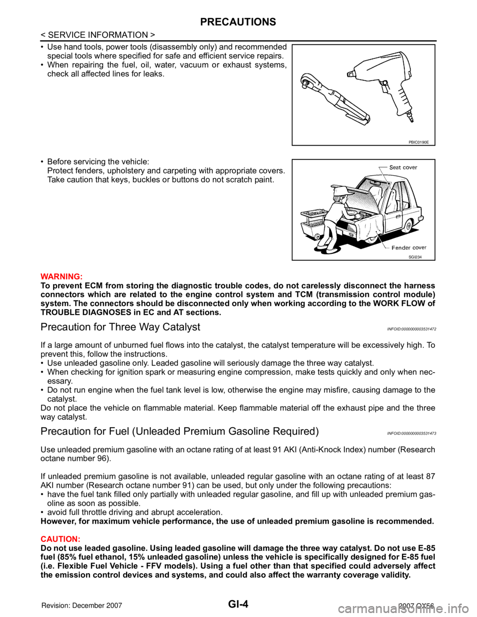
• Use hand tools, power tools (disassembly only) and recommended
special tools where specified for safe and efficient service repairs.
• When repairing the fuel, oil, water, vacuum or exhaust systems,
check all affected lines for leaks.
• Before servicing the vehicle:
Protect fenders, upholstery and carpeting with appropriate covers.
Take caution that keys, buckles or buttons do not scratch paint.
WARNING:
To prevent ECM from storing the diagnostic trouble codes, do not carelessly disconnect the harness
connectors which are related to the engine control system and TCM (transmission control module)
system. The connectors should be disconnected only when working according to the WORK FLOW of
TROUBLE DIAGNOSES in EC and AT sections.
Precaution for Three Way CatalystINFOID:0000000003531472
If a large amount of unburned fuel flows into the catalyst, the catalyst temperature will be excessively high. To
prevent this, follow the instructions.
• Use unleaded gasoline only. Leaded gasoline will seriously damage the three way catalyst.
• When checking for ignition spark or measuring engine compression, make tests quickly and only when nec-
essary.
• Do not run engine when the fuel tank level is low, otherwise the engine may misfire, causing damage to the
catalyst.
Do not place the vehicle on flammable material. Keep flammable material off the exhaust pipe and the three
way catalyst.
Precaution for Fuel (Unleaded Premium Gasoline Required)INFOID:0000000003531473
Use unleaded premium gasoline with an octane rating of at least 91 AKI (Anti-Knock Index) number (Research
octane number 96).
If unleaded premium gasoline is not available, unleaded regular gasoline with an octane rating of at least 87
AKI number (Research octane number 91) can be used, but only under the following precautions:
• have the fuel tank filled only partially with unleaded regular gasoline, and fill up with unleaded premium gas-
oline as soon as possible.
• avoid full throttle driving and abrupt acceleration.
However, for maximum vehicle performance, the use of unleaded premium gasoline is recommended.
CAUTION:
Do not use leaded gasoline. Using leaded gasoline will damage the three way catalyst. Do not use E-85
fuel (85% fuel ethanol, 15% unleaded gasoline) unless the vehicle is specifically designed for E-85 fuel
(i.e. Flexible Fuel Vehicle - FFV models). Using a fuel other than that specified could adversely affect
the emission control devices and systems, and could also affect the warranty coverage validity.
PBIC0190E
SGI234
Page 2106 of 3061
IDX-2
ALPHABETICAL INDEX
Numerics
2-4WD shift solenoid valve ..... TF-93
, TF-154, TF-167
4WD - Wiring diagram ....................................... TF-24
4WD shift switch ................................................ TF-65
4WD solenoid valve ................ TF-89, TF-154, TF-167
4WD system description .................................... TF-15
4WD system diagram ........................................ TF-19
A
A/C air flow ...................................................... ATC-30
A/C compressor clutch removal and installation .. ATC-
180
A/C compressor mounting ............................. ATC-179
A/C compressor precaution ............................. ATC-11
A/C compressor special service tool ................ ATC-14
A/C control operation (auto A/C) ...................... ATC-27
A/C diagnostic work flow (auto A/C) .............. ATC-133
A/C evaporator ............................................... ATC-186
A/C HFC134a (R134a) system identification ..... ATC-6
A/C HFC134a (R134a) system precaution ........ ATC-5
A/C HFC134a (R134a) system service procedure ATC-
175
A/C HFC134a (R134a) system service tools ... ATC-14
A/C HFC134a system service equipment precaution ...
ATC-11
A/C lubricant (R134a) ...................................... ATC-22
A/C lubrication oil ............................................. ATC-22
A/C operational check ....................... ATC-56, ATC-58
A/C self-diagnoses (auto A/C) ........ ATC-54, ATC-133
A/C service data specification ........................ ATC-193
A/C trouble diagnoses (auto A/C) .................... ATC-34
A/C, A - Wiring diagram ................................... ATC-42
A/T fluid checking ...................... AT-12, AT-51, MA-22
A/T fluid cooler cleaning .................................... AT-14
A/T fluid replacement ............................. AT-12, MA-24
A/T fluid temperature sensor ........................... AT-123
A/T IND - Wiring diagram .................................... DI-36
A/T indicator ........................................................ DI-36
A/T shift lock system ........................................ AT-216
A/T trouble diagnoses ........................................ AT-42
ABS - Wiring diagram ..................................... BRC-16
ABS (anti-lock brake system) ........................... BRC-7
Accelerator control system ............................... ACC-3
Accelerator pedal position (APP) sensor . EC-608, EC-
614, EC-628
Accelerator pedal released position learning ..... EC-80
AF1B1-Wiring diagram EC-242, EC-250, EC-258, EC-
267, EC-638
AF1B2-Wiring diagram EC-244, EC-252, EC-260, EC-
269, EC-640
AF1HB1-Wiring diagram .................................. EC-175
AF1HB2-Wiring diagram .................................. EC-177
Aiming adjustment .................................. LT-23, LT-61
Air bag .............................................................. SRS-3
Air bag precautions .............................................. AV-4
Air cleaner and air duct ..................................... EM-15
Air cleaner filter replacement ................ EM-16, MA-16
Air conditioner cut control ................................. EC-29
Air flow meter - See Mass air flow sensor EC-197, EC-
206
Air fuel ratio sensor 1 .. EC-239, EC-248, EC-256, EC-
264, EC-636
Air fuel ratio sensor 1 heater ........................... EC-174
Air mix. door motor .......................................... ATC-69
Ambient sensor ............................. ATC-138, ATC-149
Angular tightening application ............................. EM-4
Antenna .............................................................. AV-58
APPS1 - Wiring diagram ................................. EC-610
APPS2 - Wiring diagram ................................. EC-616
APPS3 - Wiring diagram ................................. EC-630
ASC/BS - Wiring diagram ............................... EC-574
ASC/SW - Wiring diagram .............................. EC-557
ASCBOF - Wiring diagram .............................. EC-648
ASCD ................................................................ EC-30
ASCD (automatic speed control device) ........... ACS-3
ASCD brake switch ........................... EC-572, EC-647
ASCD indicator lamp ....................................... EC-654
ASCD steering switch ..................................... EC-555
ASCIND - Wiring diagram ............................... EC-655
ATP switch ............................ TF-106, TF-109, TF-114
Audio .................................................................... AV-6
AUDIO - Wiring diagram .................................... AV-11
AUT/DP - Wiring diagram .................................. SE-16
Auto air conditioner - Wiring diagram .............. ATC-42
Auto anti-dazzling inside mirror ........... GW-69, GW-70
Autolamp ............................................................ LT-38
Automatic amplifier ......................................... ATC-59
Automatic drive positioner .................................. SE-11
Automatic transmission number .......................... GI-50
B
Back door ........................................................... BL-88
Back door trim ..................................................... EI-32
Back sonar .......................................................... DI-50
BACK/L - Wiring diagram ................................... LT-87
Back-up lamp ..................................................... LT-87
Ball joint (front) ................................................ FSU-15
Basic inspection ................................................ EC-73
Battery ................................................................. SC-4
Battery current sensor . EC-520, EC-527, EC-534, EC-
541
Battery/Starting/Charging System Tester SC-6, SC-12,
SC-20
BCM (Body control module) ................ BCS-3, AV-106
Block heater ...................................................... EM-78
Blower motor ................................... ATC-93, ATC-153
Body alignment ................................................ BL-164
Body component parts ..................................... BL-151
Body construction ............................................ BL-163
Body exterior paint color .................................. BL-150
Body mounting ................................................. BL-149
Body repair ....................................................... BL-150
Body sealing .................................................... BL-160
Bose speaker amp. .............................................. AV-8
Brake booster .................................................... BR-17
Page 2211 of 3061
LT-4
< SERVICE INFORMATION >
PRECAUTIONS
SERVICE INFORMATION
PRECAUTIONS
Precaution for Supplemental Restraint System (SRS) "AIR BAG" and "SEAT BELT
PRE-TENSIONER"
INFOID:0000000003533330
The Supplemental Restraint System such as “AIR BAG” and “SEAT BELT PRE-TENSIONER”, used along
with a front seat belt, helps to reduce the risk or severity of injury to the driver and front passenger for certain
types of collision. This system includes seat belt switch inputs and dual stage front air bag modules. The SRS
system uses the seat belt switches to determine the front air bag deployment, and may only deploy one front
air bag, depending on the severity of a collision and whether the front occupants are belted or unbelted.
Information necessary to service the system safely is included in the SRS and SB section of this Service Man-
ual.
WARNING:
• To avoid rendering the SRS inoperative, which could increase the risk of personal injury or death in
the event of a collision which would result in air bag inflation, all maintenance must be performed by
an authorized NISSAN/INFINITI dealer.
• Improper maintenance, including incorrect removal and installation of the SRS, can lead to personal
injury caused by unintentional activation of the system. For removal of Spiral Cable and Air Bag
Module, see the SRS section.
• Do not use electrical test equipment on any circuit related to the SRS unless instructed to in this
Service Manual. SRS wiring harnesses can be identified by yellow and/or orange harnesses or har-
ness connectors.
General precautions for service operationsINFOID:0000000003533331
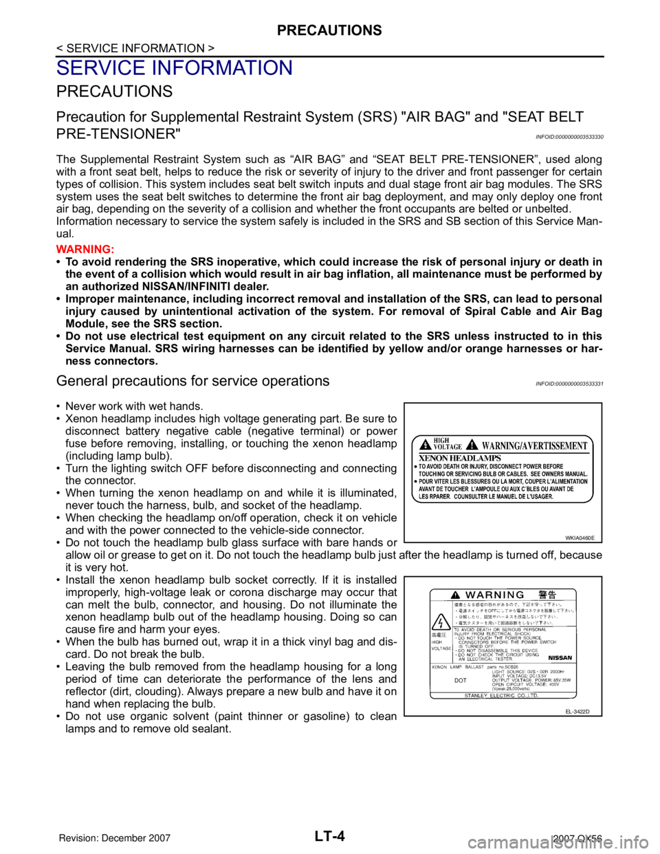
• Never work with wet hands.
• Xenon headlamp includes high voltage generating part. Be sure to
disconnect battery negative cable (negative terminal) or power
fuse before removing, installing, or touching the xenon headlamp
(including lamp bulb).
• Turn the lighting switch OFF before disconnecting and connecting
the connector.
• When turning the xenon headlamp on and while it is illuminated,
never touch the harness, bulb, and socket of the headlamp.
• When checking the headlamp on/off operation, check it on vehicle
and with the power connected to the vehicle-side connector.
• Do not touch the headlamp bulb glass surface with bare hands or
allow oil or grease to get on it. Do not touch the headlamp bulb just after the headlamp is turned off, because
it is very hot.
• Install the xenon headlamp bulb socket correctly. If it is installed
improperly, high-voltage leak or corona discharge may occur that
can melt the bulb, connector, and housing. Do not illuminate the
xenon headlamp bulb out of the headlamp housing. Doing so can
cause fire and harm your eyes.
• When the bulb has burned out, wrap it in a thick vinyl bag and dis-
card. Do not break the bulb.
• Leaving the bulb removed from the headlamp housing for a long
period of time can deteriorate the performance of the lens and
reflector (dirt, clouding). Always prepare a new bulb and have it on
hand when replacing the bulb.
• Do not use organic solvent (paint thinner or gasoline) to clean
lamps and to remove old sealant.
WKIA0460E
EL-3422D
Page 2353 of 3061
LU-8
< SERVICE INFORMATION >
ENGINE OIL
ENGINE OIL
InspectionINFOID:0000000003531555
OIL LEVEL
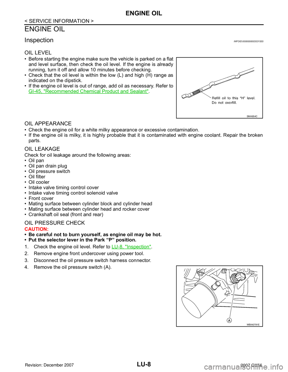
• Before starting the engine make sure the vehicle is parked on a flat
and level surface, then check the oil level. If the engine is already
running, turn it off and allow 10 minutes before checking.
• Check that the oil level is within the low (L) and high (H) range as
indicated on the dipstick.
• If the engine oil level is out of range, add oil as necessary. Refer to
GI-45, "
Recommended Chemical Product and Sealant".
OIL APPEARANCE
• Check the engine oil for a white milky appearance or excessive contamination.
• If the engine oil is milky, it is highly probable that it is contaminated with engine coolant. Repair the broken
parts.
OIL LEAKAGE
Check for oil leakage around the following areas:
•Oil pan
• Oil pan drain plug
• Oil pressure switch
• Oil filter
• Oil cooler
• Intake valve timing control cover
• Intake valve timing control solenoid valve
• Front cover
• Mating surface between cylinder block and cylinder head
• Mating surface between cylinder head and rocker cover
• Crankshaft oil seal (front and rear)
OIL PRESSURE CHECK
CAUTION:
• Be careful not to burn yourself, as engine oil may be hot.
• Put the selector lever in the Park “P” position.
1. Check the engine oil level. Refer to LU-8, "
Inspection".
2. Remove engine front undercover using power tool.
3. Disconnect the oil pressure switch harness connector.
4. Remove the oil pressure switch (A).
SMA954C
WBIA0791E
Page 2363 of 3061
MA-1
MAINTENANCE
C
D
E
F
G
H
I
J
K
M
SECTION MA
A
B
MA
N
O
P
CONTENTS
MAINTENANCE
SERVICE INFORMATION ............................2
PRECAUTIONS ...................................................2
Precaution for Supplemental Restraint System
(SRS) "AIR BAG" and "SEAT BELT PRE-TEN-
SIONER" ...................................................................
2
PREPARATION ...................................................3
Special Service Tool .................................................3
Commercial Service Tool ..........................................3
GENERAL MAINTENANCE ................................4
General Maintenance ................................................4
PERIODIC MAINTENANCE ................................6
Introduction of Periodic Maintenance ........................6
Maintenance for Off-road Driving (4WD only) ...........6
Schedule 1 ................................................................6
Schedule 2 ................................................................8
RECOMMENDED FLUIDS AND LUBRI-
CANTS ................................................................
10
Fluids and Lubricants ..............................................10
SAE Viscosity Number ............................................10
ENGINE MAINTENANCE ...................................12
Checking Drive Belts ...............................................12
Changing Engine Coolant .......................................12
Checking Fuel Line .................................................15
Changing Fuel Filter ................................................15
Changing Engine Air Cleaner Filter .........................15
Changing Engine Oil ................................................16
Changing Oil Filter ...................................................16
Changing Spark Plugs .............................................18
Checking EVAP Vapor Line .....................................19
CHASSIS AND BODY MAINTENANCE ...........20
Changing In-cabin Microfilter ...................................20
Checking Exhaust System .......................................21
Checking Automatic Transmission Fluid (ATF) .......21
Changing Automatic Transmission Fluid (ATF) .......23
Changing Transfer Fluid ..........................................23
Checking Transfer Fluid ..........................................24
Checking Propeller Shaft .........................................24
Checking Final Drive Oil ..........................................24
Changing Final Drive Oil ..........................................25
Balancing Wheels ....................................................25
Tire Rotation ............................................................27
Checking Brake Fluid Level and Leaks ...................27
CheckingBrake Line and Cables .............................27
Checking Disc Brake ...............................................27
Checking Steering Gear and Linkage ......................28
Checking Power Steering Fluid and Line ................28
Checking Axle and Suspension Parts .....................29
Lubricating Locks, Hinges and Hood Latches .........30
Checking Seat Belts, Buckles, Retractors, An-
chors and Adjusters .................................................
30