Page 2854 of 3061

TF-32
< SERVICE INFORMATION >
TROUBLE DIAGNOSIS
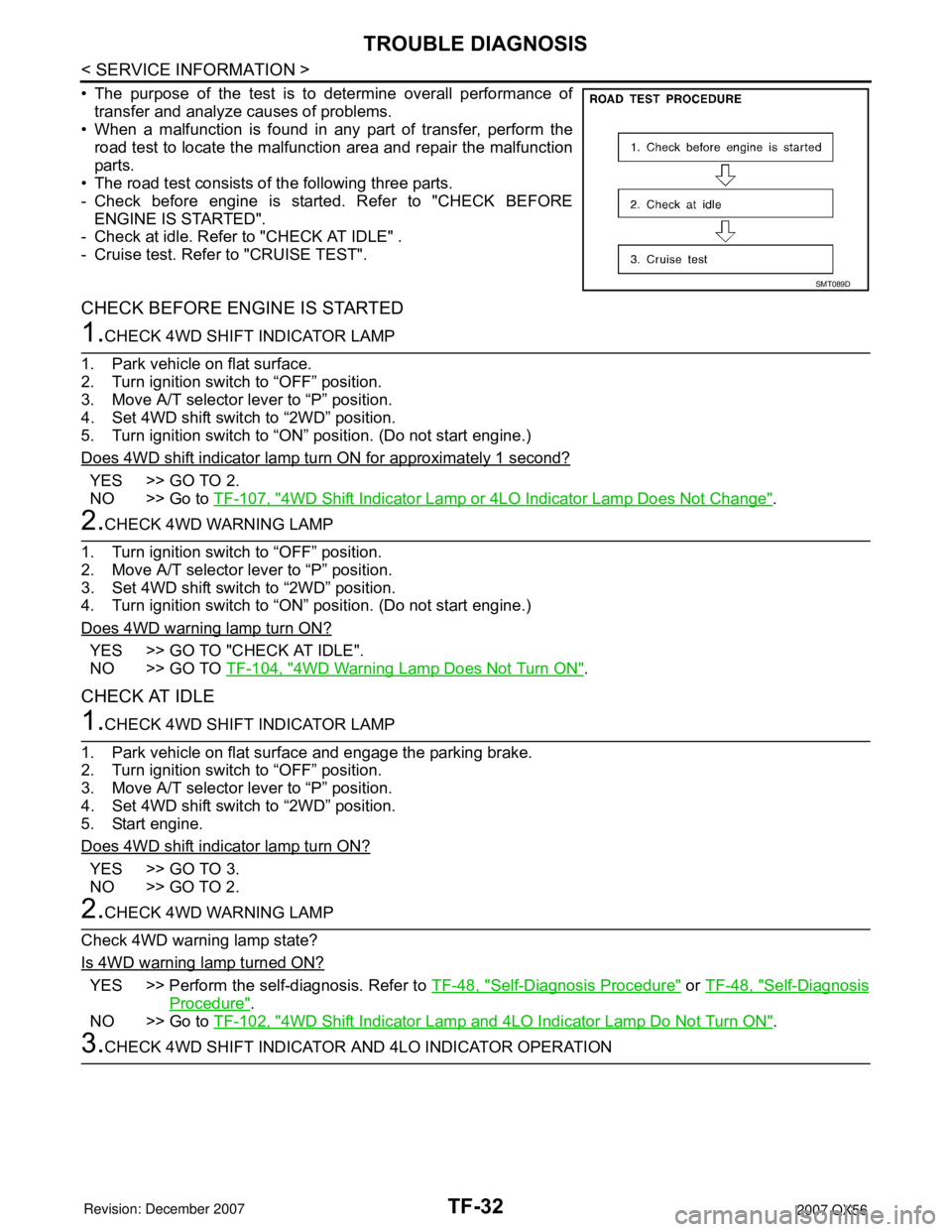
• The purpose of the test is to determine overall performance of
transfer and analyze causes of problems.
• When a malfunction is found in any part of transfer, perform the
road test to locate the malfunction area and repair the malfunction
parts.
• The road test consists of the following three parts.
- Check before engine is started. Refer to "CHECK BEFORE
ENGINE IS STARTED".
- Check at idle. Refer to "CHECK AT IDLE" .
- Cruise test. Refer to "CRUISE TEST".
CHECK BEFORE ENGINE IS STARTED
1.CHECK 4WD SHIFT INDICATOR LAMP
1. Park vehicle on flat surface.
2. Turn ignition switch to “OFF” position.
3. Move A/T selector lever to “P” position.
4. Set 4WD shift switch to “2WD” position.
5. Turn ignition switch to “ON” position. (Do not start engine.)
Does 4WD shift indicator lamp turn ON for approximately 1 second?
YES >> GO TO 2.
NO >> Go to TF-107, "
4WD Shift Indicator Lamp or 4LO Indicator Lamp Does Not Change".
2.CHECK 4WD WARNING LAMP
1. Turn ignition switch to “OFF” position.
2. Move A/T selector lever to “P” position.
3. Set 4WD shift switch to “2WD” position.
4. Turn ignition switch to “ON” position. (Do not start engine.)
Does 4WD warning lamp turn ON?
YES >> GO TO "CHECK AT IDLE".
NO >> GO TO TF-104, "
4WD Warning Lamp Does Not Turn ON".
CHECK AT IDLE
1.CHECK 4WD SHIFT INDICATOR LAMP
1. Park vehicle on flat surface and engage the parking brake.
2. Turn ignition switch to “OFF” position.
3. Move A/T selector lever to “P” position.
4. Set 4WD shift switch to “2WD” position.
5. Start engine.
Does 4WD shift indicator lamp turn ON?
YES >> GO TO 3.
NO >> GO TO 2.
2.CHECK 4WD WARNING LAMP
Check 4WD warning lamp state?
Is 4WD warning lamp turned ON?
YES >> Perform the self-diagnosis. Refer to TF-48, "Self-Diagnosis Procedure" or TF-48, "Self-Diagnosis
Procedure".
NO >> Go to TF-102, "
4WD Shift Indicator Lamp and 4LO Indicator Lamp Do Not Turn ON".
3.CHECK 4WD SHIFT INDICATOR AND 4LO INDICATOR OPERATION
SMT089D
Page 2855 of 3061

TROUBLE DIAGNOSIS
TF-33
< SERVICE INFORMATION >
C
E
F
G
H
I
J
K
L
MA
B
TF
N
O
P
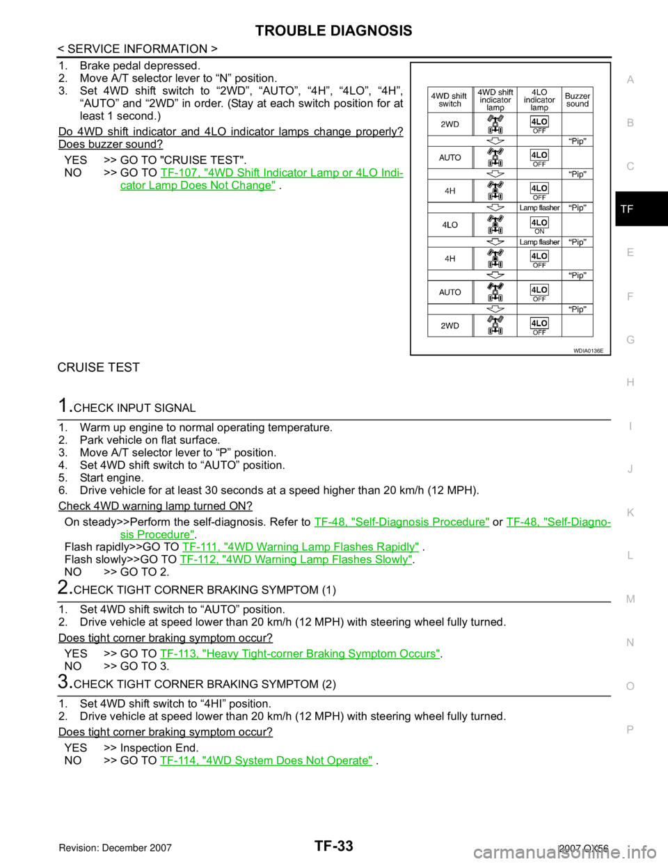
1. Brake pedal depressed.
2. Move A/T selector lever to “N” position.
3. Set 4WD shift switch to “2WD”, “AUTO”, “4H”, “4LO”, “4H”,
“AUTO” and “2WD” in order. (Stay at each switch position for at
least 1 second.)
Do 4WD shift indicator and 4LO indicator lamps change properly?
Does buzzer sound?
YES >> GO TO "CRUISE TEST".
NO >> GO TO TF-107, "
4WD Shift Indicator Lamp or 4LO Indi-
cator Lamp Does Not Change" .
CRUISE TEST
1.CHECK INPUT SIGNAL
1. Warm up engine to normal operating temperature.
2. Park vehicle on flat surface.
3. Move A/T selector lever to “P” position.
4. Set 4WD shift switch to “AUTO” position.
5. Start engine.
6. Drive vehicle for at least 30 seconds at a speed higher than 20 km/h (12 MPH).
Check 4WD warning lamp turned ON?
On steady>>Perform the self-diagnosis. Refer to TF-48, "Self-Diagnosis Procedure" or TF-48, "Self-Diagno-
sis Procedure".
Flash rapidly>>GO TO T F - 111 , "
4WD Warning Lamp Flashes Rapidly" .
Flash slowly>>GO TO TF-112, "
4WD Warning Lamp Flashes Slowly".
NO >> GO TO 2.
2.CHECK TIGHT CORNER BRAKING SYMPTOM (1)
1. Set 4WD shift switch to “AUTO” position.
2. Drive vehicle at speed lower than 20 km/h (12 MPH) with steering wheel fully turned.
Does tight corner braking symptom occur?
YES >> GO TO TF-113, "Heavy Tight-corner Braking Symptom Occurs".
NO >> GO TO 3.
3.CHECK TIGHT CORNER BRAKING SYMPTOM (2)
1. Set 4WD shift switch to “4HI” position.
2. Drive vehicle at speed lower than 20 km/h (12 MPH) with steering wheel fully turned.
Does tight corner braking symptom occur?
YES >> Inspection End.
NO >> GO TO TF-114, "
4WD System Does Not Operate" .
WDIA0136E
Page 2916 of 3061

TF-94
< SERVICE INFORMATION >
TROUBLE DIAGNOSIS FOR SYSTEM
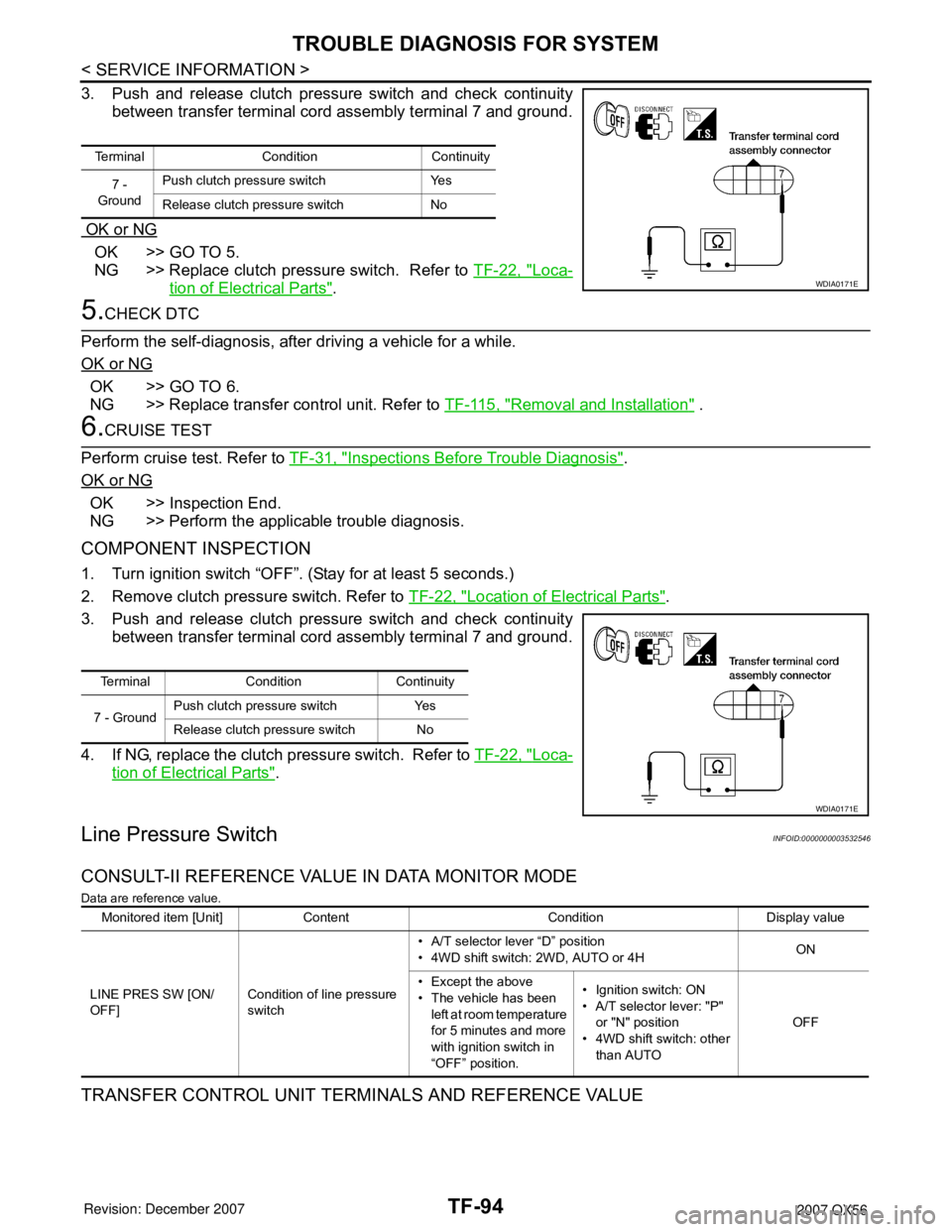
3. Push and release clutch pressure switch and check continuity
between transfer terminal cord assembly terminal 7 and ground.
OK or NG
OK >> GO TO 5.
NG >> Replace clutch pressure switch. Refer to TF-22, "
Loca-
tion of Electrical Parts".
5.CHECK DTC
Perform the self-diagnosis, after driving a vehicle for a while.
OK or NG
OK >> GO TO 6.
NG >> Replace transfer control unit. Refer to TF-115, "
Removal and Installation" .
6.CRUISE TEST
Perform cruise test. Refer to TF-31, "
Inspections Before Trouble Diagnosis".
OK or NG
OK >> Inspection End.
NG >> Perform the applicable trouble diagnosis.
COMPONENT INSPECTION
1. Turn ignition switch “OFF”. (Stay for at least 5 seconds.)
2. Remove clutch pressure switch. Refer to TF-22, "
Location of Electrical Parts".
3. Push and release clutch pressure switch and check continuity
between transfer terminal cord assembly terminal 7 and ground.
4. If NG, replace the clutch pressure switch. Refer to TF-22, "
Loca-
tion of Electrical Parts".
Line Pressure SwitchINFOID:0000000003532546
CONSULT-II REFERENCE VALUE IN DATA MONITOR MODE
Data are reference value.
TRANSFER CONTROL UNIT TERMINALS AND REFERENCE VALUE
Terminal Condition Continuity
7 -
GroundPush clutch pressure switch Yes
Release clutch pressure switch No
WDIA0171E
Terminal Condition Continuity
7 - GroundPush clutch pressure switch Yes
Release clutch pressure switch No
WDIA0171E
Monitored item [Unit] Content Condition Display value
LINE PRES SW [ON/
OFF]Condition of line pressure
switch• A/T selector lever “D” position
• 4WD shift switch: 2WD, AUTO or 4HON
• Except the above
• The vehicle has been
left at room temperature
for 5 minutes and more
with ignition switch in
“OFF” position.• Ignition switch: ON
• A/T selector lever: "P"
or "N" position
• 4WD shift switch: other
than AUTOOFF
Page 2918 of 3061

TF-96
< SERVICE INFORMATION >
TROUBLE DIAGNOSIS FOR SYSTEM
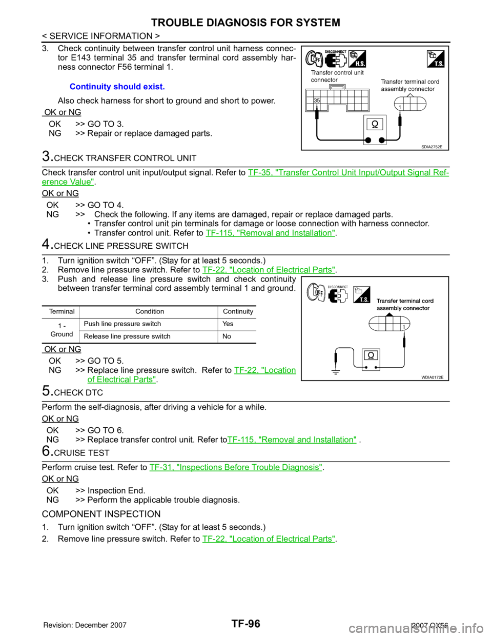
3. Check continuity between transfer control unit harness connec-
tor E143 terminal 35 and transfer terminal cord assembly har-
ness connector F56 terminal 1.
Also check harness for short to ground and short to power.
OK or NG
OK >> GO TO 3.
NG >> Repair or replace damaged parts.
3.CHECK TRANSFER CONTROL UNIT
Check transfer control unit input/output signal. Refer to TF-35, "
Transfer Control Unit Input/Output Signal Ref-
erence Value".
OK or NG
OK >> GO TO 4.
NG >> Check the following. If any items are damaged, repair or replace damaged parts.
• Transfer control unit pin terminals for damage or loose connection with harness connector.
• Transfer control unit. Refer to TF-115, "
Removal and Installation".
4.CHECK LINE PRESSURE SWITCH
1. Turn ignition switch “OFF”. (Stay for at least 5 seconds.)
2. Remove line pressure switch. Refer to TF-22, "
Location of Electrical Parts".
3. Push and release line pressure switch and check continuity
between transfer terminal cord assembly terminal 1 and ground.
OK or NG
OK >> GO TO 5.
NG >> Replace line pressure switch. Refer to TF-22, "
Location
of Electrical Parts".
5.CHECK DTC
Perform the self-diagnosis, after driving a vehicle for a while.
OK or NG
OK >> GO TO 6.
NG >> Replace transfer control unit. Refer toTF-115, "
Removal and Installation" .
6.CRUISE TEST
Perform cruise test. Refer to TF-31, "
Inspections Before Trouble Diagnosis".
OK or NG
OK >> Inspection End.
NG >> Perform the applicable trouble diagnosis.
COMPONENT INSPECTION
1. Turn ignition switch “OFF”. (Stay for at least 5 seconds.)
2. Remove line pressure switch. Refer to TF-22, "
Location of Electrical Parts". Continuity should exist.
SDIA2752E
Terminal Condition Continuity
1 -
GroundPush line pressure switch Yes
Release line pressure switch No
WDIA0172E