2007 INFINITI QX56 tire pressure
[x] Cancel search: tire pressurePage 2227 of 3061
LT-20
< SERVICE INFORMATION >
HEADLAMP (FOR USA)
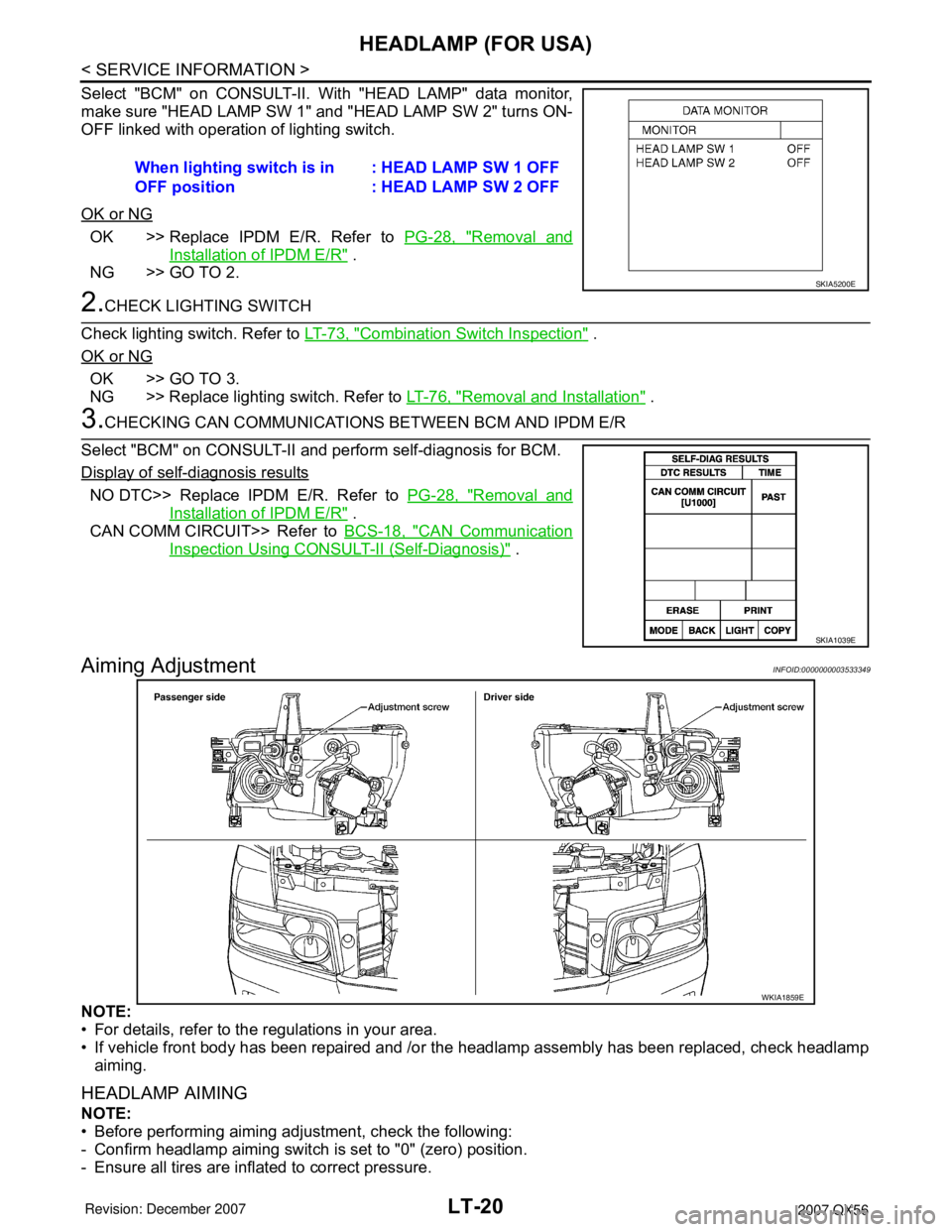
Select "BCM" on CONSULT-II. With "HEAD LAMP" data monitor,
make sure "HEAD LAMP SW 1" and "HEAD LAMP SW 2" turns ON-
OFF linked with operation of lighting switch.
OK or NG
OK >> Replace IPDM E/R. Refer to PG-28, "Removal and
Installation of IPDM E/R" .
NG >> GO TO 2.
2.CHECK LIGHTING SWITCH
Check lighting switch. Refer to LT-73, "
Combination Switch Inspection" .
OK or NG
OK >> GO TO 3.
NG >> Replace lighting switch. Refer to LT-76, "
Removal and Installation" .
3.CHECKING CAN COMMUNICATIONS BETWEEN BCM AND IPDM E/R
Select "BCM" on CONSULT-II and perform self-diagnosis for BCM.
Display of self-diagnosis results
NO DTC>> Replace IPDM E/R. Refer to PG-28, "Removal and
Installation of IPDM E/R" .
CAN COMM CIRCUIT>> Refer to BCS-18, "
CAN Communication
Inspection Using CONSULT-II (Self-Diagnosis)" .
Aiming AdjustmentINFOID:0000000003533349
NOTE:
• For details, refer to the regulations in your area.
• If vehicle front body has been repaired and /or the headlamp assembly has been replaced, check headlamp
aiming.
HEADLAMP AIMING
NOTE:
• Before performing aiming adjustment, check the following:
- Confirm headlamp aiming switch is set to "0" (zero) position.
- Ensure all tires are inflated to correct pressure.When lighting switch is in
OFF position: HEAD LAMP SW 1 OFF
: HEAD LAMP SW 2 OFF
SKIA5200E
SKIA1039E
WKIA1859E
Page 2262 of 3061
FRONT FOG LAMP
LT-55
< SERVICE INFORMATION >
C
D
E
F
G
H
I
J
L
MA
B
LT
N
O
P
Aiming AdjustmentINFOID:0000000003533400
The fog lamp is a semi-sealed beam type which uses a replaceable halogen bulb. Before performing aiming
adjustment, make sure of the following.
• Keep all tires inflated to correct pressure.
• Place vehicle on level ground.
• See that vehicle is unloaded (except for full levels of coolant,
engine oil and fuel, and spare tire, jack, and tools). Have the driver
or equivalent weight placed in driver seat.
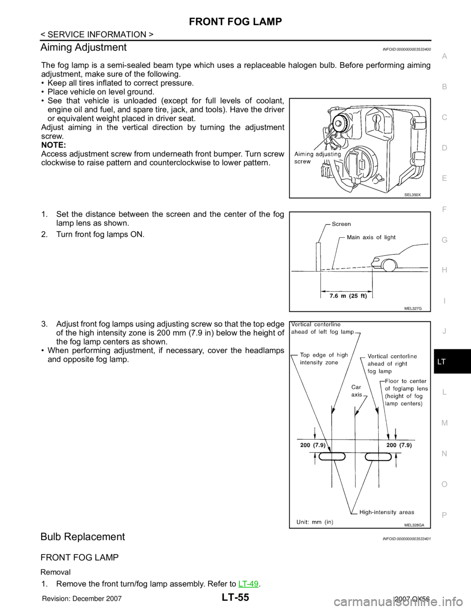
Adjust aiming in the vertical direction by turning the adjustment
screw.
NOTE:
Access adjustment screw from underneath front bumper. Turn screw
clockwise to raise pattern and counterclockwise to lower pattern.
1. Set the distance between the screen and the center of the fog
lamp lens as shown.
2. Turn front fog lamps ON.
3. Adjust front fog lamps using adjusting screw so that the top edge
of the high intensity zone is 200 mm (7.9 in) below the height of
the fog lamp centers as shown.
• When performing adjustment, if necessary, cover the headlamps
and opposite fog lamp.
Bulb ReplacementINFOID:0000000003533401
FRONT FOG LAMP
Removal
1. Remove the front turn/fog lamp assembly. Refer to LT- 4 9.
SEL350X
MEL327G
MEL328GA
Page 2366 of 3061
MA-4
< SERVICE INFORMATION >
GENERAL MAINTENANCE
GENERAL MAINTENANCE
General MaintenanceINFOID:0000000003533859
General maintenance includes those items which should be checked during the normal day-to-day operation
of the vehicle. They are essential if the vehicle is to continue operating properly. The owner can perform these
checks and inspections or have their INFINITI dealers perform them.
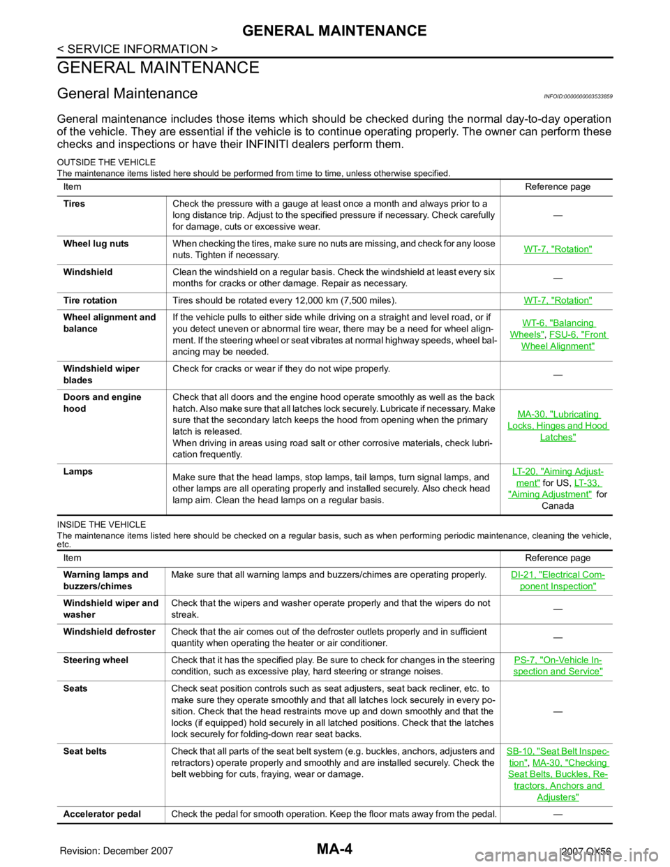
OUTSIDE THE VEHICLE
The maintenance items listed here should be performed from time to time, unless otherwise specified.
INSIDE THE VEHICLE
The maintenance items listed here should be checked on a regular basis, such as when performing periodic maintenance, cleaning the vehicle,
etc.
ItemReference page
TiresCheck the pressure with a gauge at least once a month and always prior to a
long distance trip. Adjust to the specified pressure if necessary. Check carefully
for damage, cuts or excessive wear.—
Wheel lug nutsWhen checking the tires, make sure no nuts are missing, and check for any loose
nuts. Tighten if necessary.WT-7, "
Rotation"
WindshieldClean the windshield on a regular basis. Check the windshield at least every six
months for cracks or other damage. Repair as necessary.—
Tire rotationTires should be rotated every 12,000 km (7,500 miles).WT-7, "
Rotation"
Wheel alignment and
balanceIf the vehicle pulls to either side while driving on a straight and level road, or if
you detect uneven or abnormal tire wear, there may be a need for wheel align-
ment. If the steering wheel or seat vibrates at normal highway speeds, wheel bal-
ancing may be needed.WT-6, "Balancing
Wheels", FSU-6, "Front
Wheel Alignment"
Windshield wiper
bladesCheck for cracks or wear if they do not wipe properly.
—
Doors and engine
hoodCheck that all doors and the engine hood operate smoothly as well as the back
hatch. Also make sure that all latches lock securely. Lubricate if necessary. Make
sure that the secondary latch keeps the hood from opening when the primary
latch is released.
When driving in areas using road salt or other corrosive materials, check lubri-
cation frequently.MA-30, "
Lubricating
Locks, Hinges and Hood
Latches"
Lamps
Make sure that the head lamps, stop lamps, tail lamps, turn signal lamps, and
other lamps are all operating properly and installed securely. Also check head
lamp aim. Clean the head lamps on a regular basis.LT- 2 0 , "Aiming Adjust-
ment" for US, LT- 3 3 ,
"Aiming Adjustment" for
Canada
ItemReference page
Warning lamps and
buzzers/chimesMake sure that all warning lamps and buzzers/chimes are operating properly.DI-21, "
Electrical Com-
ponent Inspection"
Windshield wiper and
washerCheck that the wipers and washer operate properly and that the wipers do not
streak.—
Windshield defrosterCheck that the air comes out of the defroster outlets properly and in sufficient
quantity when operating the heater or air conditioner.—
Steering wheelCheck that it has the specified play. Be sure to check for changes in the steering
condition, such as excessive play, hard steering or strange noises.PS-7, "
On-Vehicle In-
spection and Service"
SeatsCheck seat position controls such as seat adjusters, seat back recliner, etc. to
make sure they operate smoothly and that all latches lock securely in every po-
sition. Check that the head restraints move up and down smoothly and that the
locks (if equipped) hold securely in all latched positions. Check that the latches
lock securely for folding-down rear seat backs.—
Seat beltsCheck that all parts of the seat belt system (e.g. buckles, anchors, adjusters and
retractors) operate properly and smoothly and are installed securely. Check the
belt webbing for cuts, fraying, wear or damage.SB-10, "
Seat Belt Inspec-
tion", MA-30, "Checking
Seat Belts, Buckles, Re-
tractors, Anchors and
Adjusters"
Accelerator pedalCheck the pedal for smooth operation. Keep the floor mats away from the pedal. —
Page 2374 of 3061
MA-12
< SERVICE INFORMATION >
ENGINE MAINTENANCE
ENGINE MAINTENANCE
Checking Drive BeltsINFOID:0000000003533866
WARNING:
Be sure to perform when the engine is stopped.
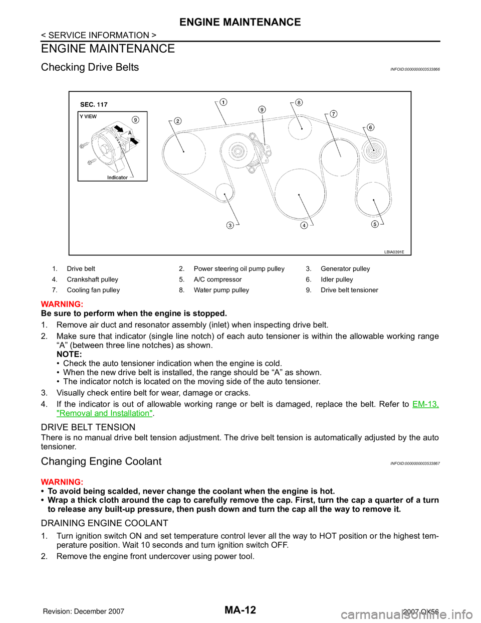
1. Remove air duct and resonator assembly (inlet) when inspecting drive belt.
2. Make sure that indicator (single line notch) of each auto tensioner is within the allowable working range
“A” (between three line notches) as shown.
NOTE:
• Check the auto tensioner indication when the engine is cold.
• When the new drive belt is installed, the range should be “A” as shown.
• The indicator notch is located on the moving side of the auto tensioner.
3. Visually check entire belt for wear, damage or cracks.
4. If the indicator is out of allowable working range or belt is damaged, replace the belt. Refer to EM-13,
"Removal and Installation".
DRIVE BELT TENSION
There is no manual drive belt tension adjustment. The drive belt tension is automatically adjusted by the auto
tensioner.
Changing Engine CoolantINFOID:0000000003533867
WARNING:
• To avoid being scalded, never change the coolant when the engine is hot.
• Wrap a thick cloth around the cap to carefully remove the cap. First, turn the cap a quarter of a turn
to release any built-up pressure, then push down and turn the cap all the way to remove it.
DRAINING ENGINE COOLANT
1. Turn ignition switch ON and set temperature control lever all the way to HOT position or the highest tem-
perature position. Wait 10 seconds and turn ignition switch OFF.
2. Remove the engine front undercover using power tool.
1. Drive belt 2. Power steering oil pump pulley 3. Generator pulley
4. Crankshaft pulley 5. A/C compressor 6. Idler pulley
7. Cooling fan pulley 8. Water pump pulley 9. Drive belt tensioner
LBIA0391E
Page 2389 of 3061
CHASSIS AND BODY MAINTENANCE
MA-27
< SERVICE INFORMATION >
C
D
E
F
G
H
I
J
K
MA
B
MA
N
O
P
5. Start wheel balancer. Make sure that inner and outer residual imbalance values are 5 g (0.18 oz) each or
below.
Wheel Balance (Maximum Allowable Imbalance)
• If either residual imbalance value exceeds 5 g (0.18 oz), repeat installation procedures.
Tire RotationINFOID:0000000003533885
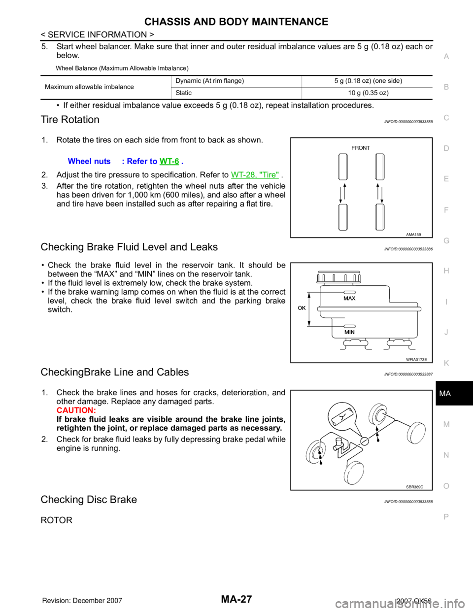
1. Rotate the tires on each side from front to back as shown.
2. Adjust the tire pressure to specification. Refer to WT-28, "
Tire" .
3. After the tire rotation, retighten the wheel nuts after the vehicle
has been driven for 1,000 km (600 miles), and also after a wheel
and tire have been installed such as after repairing a flat tire.
Checking Brake Fluid Level and LeaksINFOID:0000000003533886
• Check the brake fluid level in the reservoir tank. It should be
between the “MAX” and “MIN” lines on the reservoir tank.
• If the fluid level is extremely low, check the brake system.
• If the brake warning lamp comes on when the fluid is at the correct
level, check the brake fluid level switch and the parking brake
switch.
CheckingBrake Line and CablesINFOID:0000000003533887
1. Check the brake lines and hoses for cracks, deterioration, and
other damage. Replace any damaged parts.
CAUTION:
If brake fluid leaks are visible around the brake line joints,
retighten the joint, or replace damaged parts as necessary.
2. Check for brake fluid leaks by fully depressing brake pedal while
engine is running.
Checking Disc BrakeINFOID:0000000003533888
ROTOR
Maximum allowable imbalanceDynamic (At rim flange) 5 g (0.18 oz) (one side)
Static 10 g (0.35 oz)
Wheel nuts : Refer to WT-6 .
AMA159
WFIA0173E
SBR389C
Page 2463 of 3061

HARNESS
PG-61
< SERVICE INFORMATION >
C
D
E
F
G
H
I
J
L
MA
B
PG
N
O
P
ICC/BS EC ICC Steering Switch
ICC/SW EC ICC Brake Switch
I/MIRR GW Inside Mirror (Auto Anti-Dazzling Mirror)
IATS EC Intake Air Temperature Sensor
IGNSYS EC Ignition System
ILL LT Illumination
INJECT EC Injector
INT/L LT Room/Map, Vanity, Cargo, Personal, Foot, Step, and Puddle Lamps
KEYLES BL Remote Keyless Entry System
KS EC Knock Sensor
MAFS EC Mass Air Flow Sensor
MAIN EC Main Power Supply and Ground Circuit
METER DI Speedometer, Tachometer, Temp. and Fuel Gauges
MIL/DL EC Malfunction Indicator Lamp
MIRROR GW Door Mirror
NATS BL Nissan Anti-Theft System
NAVI AV Navigation System
O2H2B1 EC Rear Heated Oxygen Sensor 2 Heater Bank 1
O2H2B2 EC Rear Heated Oxygen Sensor 2 Heater Bank 2
O2S2B1 EC Heated Oxygen Sensor 2 Bank 1
O2S2B2 EC Heated Oxygen Sensor 2 Bank 2
P/SCKT WW Power Socket
PGC/V EC EVAP Canister Purge Volume Control Solenoid Valve
PHASE EC Camshaft Position Sensor (PHASE) (Bank 1)
PNP/SW EC Park/Neutral Position Switch
POS EC Crankshaft Position Sensor (POS)
POWER PG Power Supply Routing
PRE/SE EC EVAP Control System Pressure Sensor
PS/SEN EC Power Steering Pressure Sensor
R/VIEW DI Rear View Monitor
RP/SEN EC Refrigerant Pressure Sensor
SEN/PW EC Sensor Power Supply
SHIFT AT A/T Shift Lock System
SONAR DI Rear Sonar System
SROOF RF Sunroof
SRS SRS Supplemental Restraint System
START SC Starting System
STOP/L LT Stop Lamp
T/TOW LT Trailer Tow
T/WARN WT Low Tire Pressure Warning System
TAIL/L LT Parking, License and Tail Lamps
T/F TF Transfer Case
TPS1 EC Throttle Position Sensor
TPS2 EC Throttle Position Sensor
TPS3 EC Throttle Position Sensor
TRNSCV BL HOMELINK® Universal Transceiver
TURN LT Turn Signal and Hazard Warning Lamps
VDC BRC Vehicle Dynamic Control System
VEHSEC BL Vehicle security (theft warning) system
VENT/V EC EVAP Canister Vent Control Valve
W/ANT AV Audio Antenna
WARN DI Warning Lamps
Page 2498 of 3061
STEERING WHEEL
PS-7
< SERVICE INFORMATION >
C
D
E
F
H
I
J
K
L
MA
B
PS
N
O
P
STEERING WHEEL
On-Vehicle Inspection and ServiceINFOID:0000000003532824
CHECKING CONDITION OF INSTALLATION
• Check installation condition of steering gear assembly, front suspension, axle and steering column.
• Check if movement exists when steering wheel is moved up and down, to the left and right and to the axial
direction.
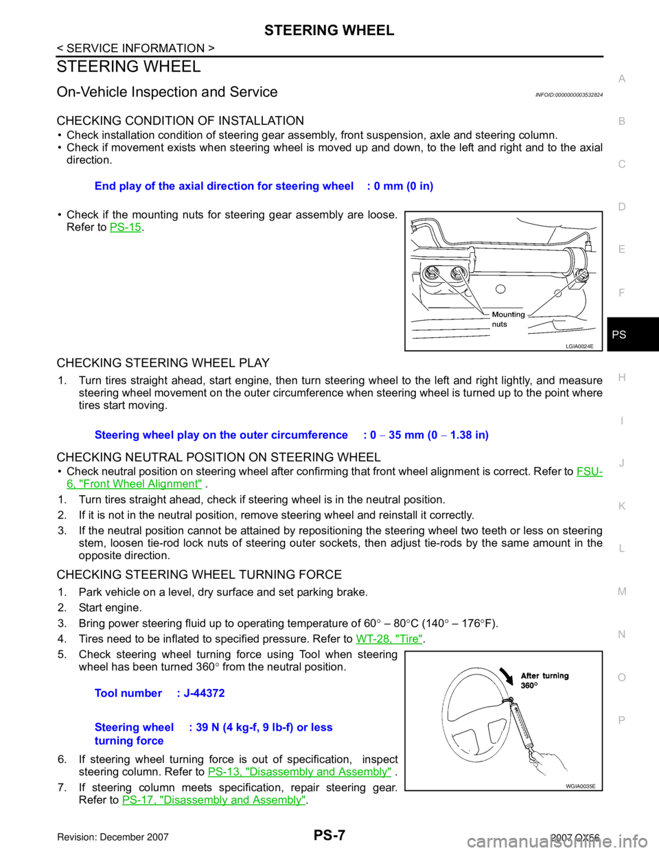
• Check if the mounting nuts for steering gear assembly are loose.
Refer to PS-15
.
CHECKING STEERING WHEEL PLAY
1. Turn tires straight ahead, start engine, then turn steering wheel to the left and right lightly, and measure
steering wheel movement on the outer circumference when steering wheel is turned up to the point where
tires start moving.
CHECKING NEUTRAL POSITION ON STEERING WHEEL
• Check neutral position on steering wheel after confirming that front wheel alignment is correct. Refer to FSU-
6, "Front Wheel Alignment" .
1. Turn tires straight ahead, check if steering wheel is in the neutral position.
2. If it is not in the neutral position, remove steering wheel and reinstall it correctly.
3. If the neutral position cannot be attained by repositioning the steering wheel two teeth or less on steering
stem, loosen tie-rod lock nuts of steering outer sockets, then adjust tie-rods by the same amount in the
opposite direction.
CHECKING STEERING WHEEL TURNING FORCE
1. Park vehicle on a level, dry surface and set parking brake.
2. Start engine.
3. Bring power steering fluid up to operating temperature of 60° – 80°C (140° – 176°F).
4. Tires need to be inflated to specified pressure. Refer to WT-28, "
Tire".
5. Check steering wheel turning force using Tool when steering
wheel has been turned 360° from the neutral position.
6. If steering wheel turning force is out of specification, inspect
steering column. Refer to PS-13, "
Disassembly and Assembly" .
7. If steering column meets specification, repair steering gear.
Refer to PS-17, "
Disassembly and Assembly". End play of the axial direction for steering wheel : 0 mm (0 in)
LGIA0024E
Steering wheel play on the outer circumference : 0 − 35 mm (0 − 1.38 in)
Tool number : J-44372
Steering wheel
turning force: 39 N (4 kg-f, 9 lb-f) or less
WGIA0035E
Page 2613 of 3061
REAR SUSPENSION ASSEMBLY
RSU-23
< SERVICE INFORMATION >
C
D
F
G
H
I
J
K
L
MA
B
RSU
N
O
P
Wheel AlignmentInspectionINFOID:0000000003532671
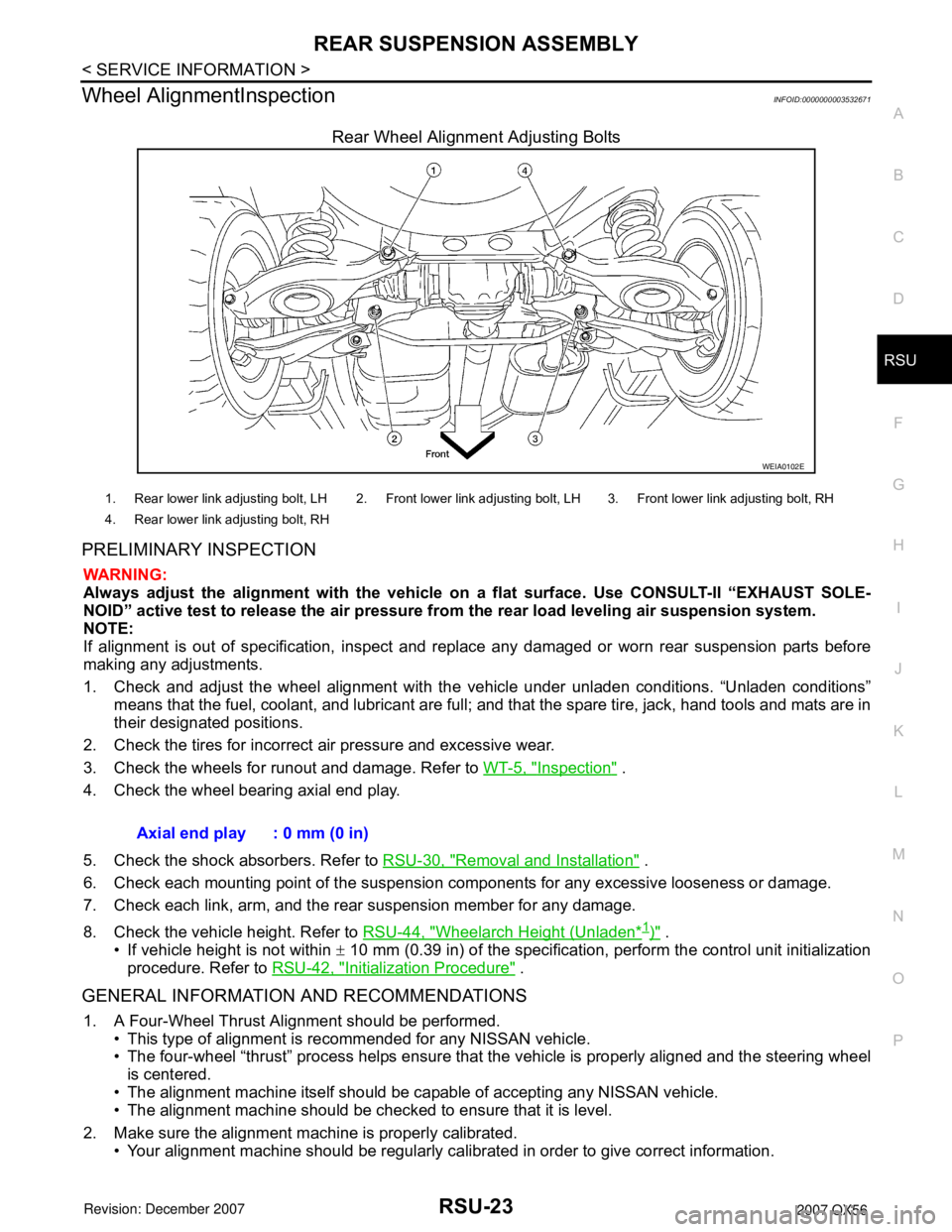
Rear Wheel Alignment Adjusting Bolts
PRELIMINARY INSPECTION
WARNING:
Always adjust the alignment with the vehicle on a flat surface. Use CONSULT-II “EXHAUST SOLE-
NOID” active test to release the air pressure from the rear load leveling air suspension system.
NOTE:
If alignment is out of specification, inspect and replace any damaged or worn rear suspension parts before
making any adjustments.
1. Check and adjust the wheel alignment with the vehicle under unladen conditions. “Unladen conditions”
means that the fuel, coolant, and lubricant are full; and that the spare tire, jack, hand tools and mats are in
their designated positions.
2. Check the tires for incorrect air pressure and excessive wear.
3. Check the wheels for runout and damage. Refer to WT-5, "
Inspection" .
4. Check the wheel bearing axial end play.
5. Check the shock absorbers. Refer to RSU-30, "
Removal and Installation" .
6. Check each mounting point of the suspension components for any excessive looseness or damage.
7. Check each link, arm, and the rear suspension member for any damage.
8. Check the vehicle height. Refer to RSU-44, "
Wheelarch Height (Unladen*1)" .
• If vehicle height is not within ± 10 mm (0.39 in) of the specification, perform the control unit initialization
procedure. Refer to RSU-42, "
Initialization Procedure" .
GENERAL INFORMATION AND RECOMMENDATIONS
1. A Four-Wheel Thrust Alignment should be performed.
• This type of alignment is recommended for any NISSAN vehicle.
• The four-wheel “thrust” process helps ensure that the vehicle is properly aligned and the steering wheel
is centered.
• The alignment machine itself should be capable of accepting any NISSAN vehicle.
• The alignment machine should be checked to ensure that it is level.
2. Make sure the alignment machine is properly calibrated.
• Your alignment machine should be regularly calibrated in order to give correct information.
WEIA0102E
1. Rear lower link adjusting bolt, LH 2. Front lower link adjusting bolt, LH 3. Front lower link adjusting bolt, RH
4. Rear lower link adjusting bolt, RH
Axial end play : 0 mm (0 in)