Page 2462 of 3061

PG-60
< SERVICE INFORMATION >
HARNESS
Code Section Wiring Diagram Name
A/C,A ATC Auto Air Conditioner
A/SUSP RSU Rear Air Suspension
AF1B1 EC Air Fuel Ratio (A/F) Sensor 1 (Bank 1)
AF1B2 EC Air Fuel Ratio (A/F) Sensor 1 (Bank 2)
AF1HB1 EC Air Fuel Ratio (A/F) Sensor 1 (Bank 1)
AF1HB2 EC Air Fuel Ratio (A/F) Sensor 1 (Bank 2)
APPS1 EC Accelerator Pedal Position Sensor
APPS2 EC Accelerator Pedal Position Sensor
APPS3 EC Accelerator Pedal Position Sensor
ASC/BS EC ASCD Brake Switch
ASC/SW EC ASCD Steering Switch
ASCBOF EC ASCD Brake Switch
ASCIND EC ASCD Indicator
A/T AT A/T Assembly
AT/IND DI A/T Indicator Lamp
AUDIO AV Audio
AUT/DP SE Automatic Drive Positioner
AUTO/L LT Auto Light Control
B/CLOS BL Back Door Auto Closure System
BACK/L LT Back-up Lamp
BRK/SW EC Brake Switch
CAN EC CAN Communication Line
CAN LAN CAN System
CHARGE SC Charging System
CHIME DI Warning Chime
CLOCK DI Clock
COOL/F EC Cooling Fan Control
COMBSW LT Combination Switch
COMM AV Audio Visual Communication System
COMPAS DI Compass and Thermometer
D/LOCK BL Power Door Lock
DEF GW Rear Window Defogger
DTRL LT Headlamp - With Daytime Light System
DVD AV DVD Entertainment System
ECM/PW EC ECM Power Supply for Back-Up
ECTS EC Engine Coolant Temperature Sensor
ETC1 EC Electric Throttle Control Function
ETC2 EC Throttle Control Motor Relay
ETC3 EC Throttle Control Motor
F/FOG LT Front Fog Lamp
F/PUMP EC Fuel Pump
FTTS EC Fuel Tank Temperature Sensor
FUELB1 EC Fuel Injection System Bank 1
FUELB2 EC Fuel Injection System Bank 2
H/AIM LT Headlamp Aiming Control
H/PHON AV Hands Free Telephone
H/LAMP LT Headlamp
HORN WW Horn
HSEAT SE Heated Seat
ICC ACS Intelligent Cruise Control
ICCBOF EC ICC Brake Switch
Page 2916 of 3061

TF-94
< SERVICE INFORMATION >
TROUBLE DIAGNOSIS FOR SYSTEM
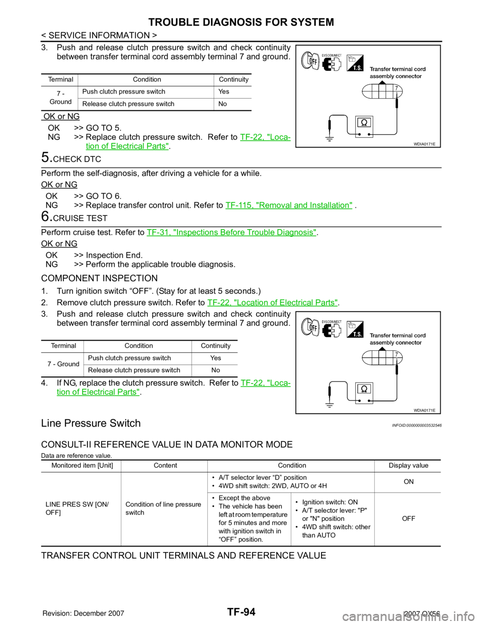
3. Push and release clutch pressure switch and check continuity
between transfer terminal cord assembly terminal 7 and ground.
OK or NG
OK >> GO TO 5.
NG >> Replace clutch pressure switch. Refer to TF-22, "
Loca-
tion of Electrical Parts".
5.CHECK DTC
Perform the self-diagnosis, after driving a vehicle for a while.
OK or NG
OK >> GO TO 6.
NG >> Replace transfer control unit. Refer to TF-115, "
Removal and Installation" .
6.CRUISE TEST
Perform cruise test. Refer to TF-31, "
Inspections Before Trouble Diagnosis".
OK or NG
OK >> Inspection End.
NG >> Perform the applicable trouble diagnosis.
COMPONENT INSPECTION
1. Turn ignition switch “OFF”. (Stay for at least 5 seconds.)
2. Remove clutch pressure switch. Refer to TF-22, "
Location of Electrical Parts".
3. Push and release clutch pressure switch and check continuity
between transfer terminal cord assembly terminal 7 and ground.
4. If NG, replace the clutch pressure switch. Refer to TF-22, "
Loca-
tion of Electrical Parts".
Line Pressure SwitchINFOID:0000000003532546
CONSULT-II REFERENCE VALUE IN DATA MONITOR MODE
Data are reference value.
TRANSFER CONTROL UNIT TERMINALS AND REFERENCE VALUE
Terminal Condition Continuity
7 -
GroundPush clutch pressure switch Yes
Release clutch pressure switch No
WDIA0171E
Terminal Condition Continuity
7 - GroundPush clutch pressure switch Yes
Release clutch pressure switch No
WDIA0171E
Monitored item [Unit] Content Condition Display value
LINE PRES SW [ON/
OFF]Condition of line pressure
switch• A/T selector lever “D” position
• 4WD shift switch: 2WD, AUTO or 4HON
• Except the above
• The vehicle has been
left at room temperature
for 5 minutes and more
with ignition switch in
“OFF” position.• Ignition switch: ON
• A/T selector lever: "P"
or "N" position
• 4WD shift switch: other
than AUTOOFF
Page 2918 of 3061

TF-96
< SERVICE INFORMATION >
TROUBLE DIAGNOSIS FOR SYSTEM
3. Check continuity between transfer control unit harness connec-
tor E143 terminal 35 and transfer terminal cord assembly har-
ness connector F56 terminal 1.
Also check harness for short to ground and short to power.
OK or NG
OK >> GO TO 3.
NG >> Repair or replace damaged parts.
3.CHECK TRANSFER CONTROL UNIT
Check transfer control unit input/output signal. Refer to TF-35, "
Transfer Control Unit Input/Output Signal Ref-
erence Value".
OK or NG
OK >> GO TO 4.
NG >> Check the following. If any items are damaged, repair or replace damaged parts.
• Transfer control unit pin terminals for damage or loose connection with harness connector.
• Transfer control unit. Refer to TF-115, "
Removal and Installation".
4.CHECK LINE PRESSURE SWITCH
1. Turn ignition switch “OFF”. (Stay for at least 5 seconds.)
2. Remove line pressure switch. Refer to TF-22, "
Location of Electrical Parts".
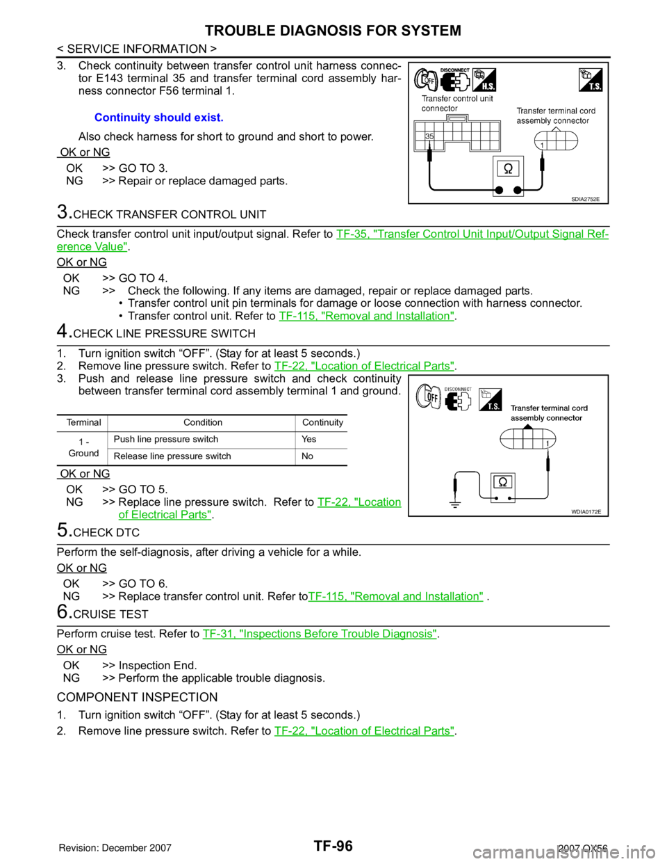
3. Push and release line pressure switch and check continuity
between transfer terminal cord assembly terminal 1 and ground.
OK or NG
OK >> GO TO 5.
NG >> Replace line pressure switch. Refer to TF-22, "
Location
of Electrical Parts".
5.CHECK DTC
Perform the self-diagnosis, after driving a vehicle for a while.
OK or NG
OK >> GO TO 6.
NG >> Replace transfer control unit. Refer toTF-115, "
Removal and Installation" .
6.CRUISE TEST
Perform cruise test. Refer to TF-31, "
Inspections Before Trouble Diagnosis".
OK or NG
OK >> Inspection End.
NG >> Perform the applicable trouble diagnosis.
COMPONENT INSPECTION
1. Turn ignition switch “OFF”. (Stay for at least 5 seconds.)
2. Remove line pressure switch. Refer to TF-22, "
Location of Electrical Parts". Continuity should exist.
SDIA2752E
Terminal Condition Continuity
1 -
GroundPush line pressure switch Yes
Release line pressure switch No
WDIA0172E