2007 INFINITI QX56 engine
[x] Cancel search: enginePage 1085 of 3061

EC-2
CONSULT-II Function (ENGINE) ..........................111
Generic Scan Tool (GST) Function .......................122
CONSULT-II Reference Value in Data Monitor
Mode ......................................................................
124
Major Sensor Reference Graph in Data Monitor
Mode ......................................................................
127
TROUBLE DIAGNOSIS - SPECIFICATION
VALUE .............................................................
129
Description .............................................................129
Testing Condition ...................................................129
Inspection Procedure .............................................129
Diagnosis Procedure .............................................130
TROUBLE DIAGNOSIS FOR INTERMITTENT
INCIDENT ........................................................
138
Description .............................................................138
Diagnosis Procedure .............................................138
POWER SUPPLY AND GROUND CIRCUIT ...139
Wiring Diagram ......................................................139
Diagnosis Procedure .............................................140
Ground Inspection .................................................143
DTC U1000, U1001 CAN COMMUNICATION
LINE .................................................................
145
Description .............................................................145
On Board Diagnosis Logic .....................................145
DTC Confirmation Procedure ................................145
Wiring Diagram ......................................................146
Diagnosis Procedure .............................................146
DTC U1010 CAN COMMUNICATION .............147
Description .............................................................147
On Board Diagnosis Logic .....................................147
DTC Confirmation Procedure ................................147
Diagnosis Procedure .............................................147
DTC P0011, P0021 IVT CONTROL .................149
Description .............................................................149
CONSULT-II Reference Value in Data Monitor
Mode ......................................................................
150
On Board Diagnosis Logic .....................................150
DTC Confirmation Procedure ................................150
Wiring Diagram ......................................................152
Diagnosis Procedure .............................................155
Component Inspection ...........................................159
Removal and Installation .......................................160
DTC P0031, P0032, P0051, P0052 A/F SEN-
SOR 1 HEATER ...............................................
163
Description .............................................................163
CONSULT-II Reference Value in Data Monitor
Mode ......................................................................
163
On Board Diagnosis Logic .....................................163
DTC Confirmation Procedure ................................163
Wiring Diagram ......................................................164
Diagnosis Procedure .............................................167
Component Inspection ...........................................168
Removal and Installation .......................................169
DTC P0037, P0038, P0057, P0058 HO2S2
HEATER ...........................................................
170
Description ............................................................170
CONSULT-II Reference Value in Data Monitor
Mode .....................................................................
170
On Board Diagnosis Logic ....................................170
DTC Confirmation Procedure ................................170
Wiring Diagram .....................................................172
Diagnosis Procedure .............................................175
Component Inspection ..........................................176
Removal and Installation .......................................177
DTC P0075, P0081 IVT CONTROL SOLE-
NOID VALVE ....................................................
178
Component Description ........................................178
CONSULT-II Reference Value in Data Monitor
Mode .....................................................................
178
On Board Diagnosis Logic ....................................178
DTC Confirmation Procedure ................................178
Wiring Diagram .....................................................179
Diagnosis Procedure .............................................182
Component Inspection ..........................................183
Removal and Installation .......................................184
DTC P0101 MAF SENSOR ..............................186
Component Description ........................................186
CONSULT-II Reference Value in Data Monitor
Mode .....................................................................
186
On Board Diagnosis Logic ....................................186
DTC Confirmation Procedure ................................186
Overall Function Check .........................................188
Wiring Diagram .....................................................189
Diagnosis Procedure .............................................190
Component Inspection ..........................................192
Removal and Installation .......................................193
DTC P0102, P0103 MAF SENSOR ..................194
Component Description ........................................194
CONSULT-II Reference Value in Data Monitor
Mode .....................................................................
194
On Board Diagnosis Logic ....................................194
DTC Confirmation Procedure ................................194
Wiring Diagram .....................................................196
Diagnosis Procedure .............................................197
Component Inspection ..........................................199
Removal and Installation .......................................200
DTC P0112, P0113 IAT SENSOR ....................201
Component Description ........................................201
On Board Diagnosis Logic ....................................201
DTC Confirmation Procedure ................................201
Wiring Diagram .....................................................202
Diagnosis Procedure .............................................202
Component Inspection ..........................................204
Removal and Installation .......................................204
DTC P0117, P0118 ECT SENSOR ...................205
Component Description ........................................205
On Board Diagnosis Logic ....................................205
DTC Confirmation Procedure ................................206
Page 1089 of 3061

EC-6
DTC P0605 ECM ..............................................444
Component Description .........................................444
On Board Diagnosis Logic .....................................444
DTC Confirmation Procedure ................................444
Diagnosis Procedure .............................................445
DTC P0643 SENSOR POWER SUPPLY ........447
On Board Diagnosis Logic .....................................447
DTC Confirmation Procedure ................................447
Wiring Diagram ......................................................448
Diagnosis Procedure .............................................449
DTC P0850 PNP SWITCH ...............................452
Component Description .........................................452
CONSULT-II Reference Value in Data Monitor
Mode ......................................................................
452
On Board Diagnosis Logic .....................................452
DTC Confirmation Procedure ................................452
Overall Function Check .........................................453
Wiring Diagram ......................................................454
Diagnosis Procedure .............................................455
DTC P1140, P1145 IVT CONTROL POSITION
SENSOR ..........................................................
457
Component Description .........................................457
CONSULT-II Reference Value in Data Monitor
Mode ......................................................................
457
On Board Diagnosis Logic .....................................457
DTC Confirmation Procedure ................................457
Wiring Diagram ......................................................458
Diagnosis Procedure .............................................461
Component Inspection ...........................................463
Removal and Installation .......................................464
DTC P1148, P1168 CLOSED LOOP CON-
TROL ................................................................
466
On Board Diagnosis Logic .....................................466
DTC P1211 TCS CONTROL UNIT ..................467
Description .............................................................467
On Board Diagnosis Logic .....................................467
DTC Confirmation Procedure ................................467
Diagnosis Procedure .............................................467
DTC P1212 TCS COMMUNICATION LINE .....468
Description .............................................................468
On Board Diagnosis Logic .....................................468
DTC Confirmation Procedure ................................468
Diagnosis Procedure .............................................468
DTC P1217 ENGINE OVER TEMPERATURE .469
Description .............................................................469
CONSULT-II Reference Value in Data Monitor
Mode ......................................................................
469
On Board Diagnosis Logic .....................................470
Overall Function Check .........................................470
Wiring Diagram ......................................................472
Diagnosis Procedure .............................................473
Main 13 Causes of Overheating ............................476
Component Inspection ...........................................476
DTC P1225 TP SENSOR ..................................477
Component Description ........................................477
On Board Diagnosis Logic ....................................477
DTC Confirmation Procedure ................................477
Diagnosis Procedure .............................................477
Removal and Installation .......................................478
DTC P1226 TP SENSOR ..................................479
Component Description ........................................479
On Board Diagnosis Logic ....................................479
DTC Confirmation Procedure ................................479
Diagnosis Procedure .............................................479
Removal and Installation .......................................480
DTC P1421 COLD START CONTROL ............481
Description ............................................................481
On Board Diagnosis Logic ....................................481
DTC Confirmation Procedure ................................481
Diagnosis Procedure .............................................481
DTC P1550 BATTERY CURRENT SENSOR ...483
Component Description ........................................483
CONSULT-II Reference Value in Data Monitor
Mode .....................................................................
483
On Board Diagnosis Logic ....................................483
DTC Confirmation Procedure ................................483
Wiring Diagram .....................................................485
Diagnosis Procedure .............................................486
Component Inspection ..........................................488
DTC P1551, P1552 BATTERY CURRENT
SENSOR ...........................................................
489
Component Description ........................................489
CONSULT-II Reference Value in Data Monitor
Mode .....................................................................
489
On Board Diagnosis Logic ....................................489
DTC Confirmation Procedure ................................489
Wiring Diagram .....................................................491
Diagnosis Procedure .............................................492
Component Inspection ..........................................494
DTC P1553 BATTERY CURRENT SENSOR ...495
Component Description ........................................495
CONSULT-II Reference Value in Data Monitor
Mode .....................................................................
495
On Board Diagnosis Logic ....................................495
DTC Confirmation Procedure ................................495
Wiring Diagram .....................................................497
Diagnosis Procedure .............................................498
Component Inspection ..........................................500
DTC P1554 BATTERY CURRENT SENSOR ...501
Component Description ........................................501
CONSULT-II Reference Value in Data Monitor
Mode .....................................................................
501
On Board Diagnosis Logic ....................................501
Overall Function Check .........................................501
Wiring Diagram .....................................................503
Diagnosis Procedure .............................................504
Component Inspection ..........................................506
Page 1091 of 3061

EC-8
DTC Confirmation Procedure ................................567
Wiring Diagram ......................................................569
Diagnosis Procedure .............................................570
Component Inspection ...........................................572
Removal and Installation .......................................573
DTC P2135 TP SENSOR .................................574
Component Description .........................................574
CONSULT-II Reference Value in Data Monitor
Mode ......................................................................
574
On Board Diagnosis Logic .....................................574
DTC Confirmation Procedure ................................574
Wiring Diagram ......................................................576
Diagnosis Procedure .............................................577
Component Inspection ...........................................579
Removal and Installation .......................................580
DTC P2138 APP SENSOR ..............................581
Component Description .........................................581
CONSULT-II Reference Value in Data Monitor
Mode ......................................................................
581
On Board Diagnosis Logic .....................................581
DTC Confirmation Procedure ................................582
Wiring Diagram ......................................................583
Diagnosis Procedure .............................................584
Component Inspection ...........................................587
Removal and Installation .......................................587
DTC P2A00, P2A03 A/F SENSOR 1 ...............588
Component Description .........................................588
CONSULT-II Reference Value in Data Monitor
Mode ......................................................................
588
On Board Diagnosis Logic .....................................588
DTC Confirmation Procedure ................................588
Wiring Diagram ......................................................590
Diagnosis Procedure .............................................593
Removal and Installation .......................................596
ASCD BRAKE SWITCH ..................................597
Component Description .........................................597
CONSULT-II Reference Value in Data Monitor
Mode ......................................................................
597
Wiring Diagram ......................................................598
Diagnosis Procedure .............................................599
Component Inspection ...........................................602
ASCD INDICATOR ..........................................603
Component Description .........................................603
CONSULT-II Reference Value in Data Monitor
Mode ......................................................................
603
Wiring Diagram ......................................................604
Diagnosis Procedure .............................................604
ELECTRICAL LOAD SIGNAL .........................606
Description .............................................................606
CONSULT-II Reference Value in Data Monitor
Mode ......................................................................
606
Diagnosis Procedure .............................................606
FUEL INJECTOR ..............................................608
Component Description ........................................608
CONSULT-II Reference Value in Data Monitor
Mode .....................................................................
608
Wiring Diagram .....................................................609
Diagnosis Procedure .............................................610
Component Inspection ..........................................612
Removal and Installation .......................................612
FUEL PUMP .....................................................613
Description ............................................................613
CONSULT-II Reference Value in Data Monitor
Mode .....................................................................
613
Wiring Diagram .....................................................614
Diagnosis Procedure .............................................615
Component Inspection ..........................................617
Removal and Installation .......................................618
ICC BRAKE SWITCH .......................................619
Component Description ........................................619
CONSULT-II Reference Value in Data Monitor
Mode .....................................................................
619
Wiring Diagram .....................................................620
Diagnosis Procedure .............................................621
Component Inspection ..........................................624
IGNITION SIGNAL ............................................626
Component Description ........................................626
Wiring Diagram .....................................................627
Diagnosis Procedure .............................................632
Component Inspection ..........................................635
Removal and Installation .......................................637
REFRIGERANT PRESSURE SENSOR ...........638
Component Description ........................................638
Wiring Diagram .....................................................639
Diagnosis Procedure .............................................640
Removal and Installation .......................................642
MIL AND DATA LINK CONNECTOR ...............643
Wiring Diagram .....................................................643
SERVICE DATA AND SPECIFICATIONS
(SDS) ................................................................
645
Fuel Pressure ........................................................645
Idle Speed and Ignition Timing .............................645
Calculated Load Value ..........................................645
Mass Air Flow Sensor ...........................................645
Intake Air Temperature Sensor .............................645
Engine Coolant Temperature Sensor ...................645
A/F Sensor 1 Heater .............................................645
Heated Oxygen sensor 2 Heater ..........................645
Crankshaft Position Sensor (POS) .......................646
Camshaft Position Sensor (PHASE) .....................646
Throttle Control Motor ...........................................646
Fuel Injector ..........................................................646
Fuel Pump .............................................................646
Page 1100 of 3061
PRECAUTIONS
EC-17
< SERVICE INFORMATION >
C
D
E
F
G
H
I
J
K
L
MA
EC
N
P O
PRECAUTIONS
Precaution for Supplemental Restraint System (SRS) "AIR BAG" and "SEAT BELT
PRE-TENSIONER"
INFOID:0000000003531580
The Supplemental Restraint System such as “AIR BAG” and “SEAT BELT PRE-TENSIONER”, used along
with a front seat belt, helps to reduce the risk or severity of injury to the driver and front passenger for certain
types of collision. This system includes seat belt switch inputs and dual stage front air bag modules. The SRS
system uses the seat belt switches to determine the front air bag deployment, and may only deploy one front
air bag, depending on the severity of a collision and whether the front occupants are belted or unbelted.
Information necessary to service the system safely is included in the SRS and SB section of this Service Man-
ual.
WARNING:
• To avoid rendering the SRS inoperative, which could increase the risk of personal injury or death in
the event of a collision which would result in air bag inflation, all maintenance must be performed by
an authorized NISSAN/INFINITI dealer.
• Improper maintenance, including incorrect removal and installation of the SRS, can lead to personal
injury caused by unintentional activation of the system. For removal of Spiral Cable and Air Bag
Module, see the SRS section.
• Do not use electrical test equipment on any circuit related to the SRS unless instructed to in this
Service Manual. SRS wiring harnesses can be identified by yellow and/or orange harnesses or har-
ness connectors.
On Board Diagnosis (OBD) System of Engine and A/TINFOID:0000000003531581
The ECM has an on board diagnostic system. It will light up the malfunction indicator lamp (MIL) to warn the
driver of a malfunction causing emission deterioration.
CAUTION:
• Be sure to turn the ignition switch OFF and disconnect the negative battery cable before any repair
or inspection work. The open/short circuit of related switches, sensors, solenoid valves, etc. will
cause the MIL to light up.
• Be sure to connect and lock the connectors securely after work. A loose (unlocked) connector will
cause the MIL to light up due to the open circuit. (Be sure the connector is free from water, grease,
dirt, bent terminals, etc.)
• Certain systems and components, especially those related to OBD, may use a new style slide-lock-
ing type harness connector. For description and how to disconnect, refer to PG-66
.
• Be sure to route and secure the harnesses properly after work. The interference of the harness with
a bracket, etc. may cause the MIL to light up due to the short circuit.
• Be sure to connect rubber tubes properly after work. A misconnected or disconnected rubber tube
may cause the MIL to light up due to the malfunction of the EVAP system or fuel injection system,
etc.
• Be sure to erase the unnecessary malfunction information (repairs completed) from the ECM and
TCM (Transmission control module) before returning the vehicle to the customer.
PrecautionINFOID:0000000003531582
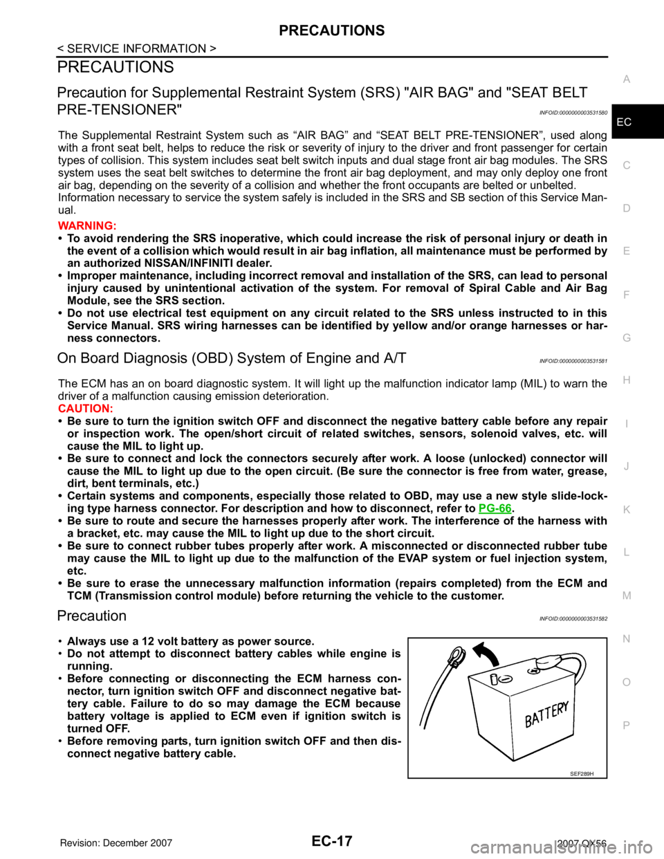
•Always use a 12 volt battery as power source.
•Do not attempt to disconnect battery cables while engine is
running.
•Before connecting or disconnecting the ECM harness con-
nector, turn ignition switch OFF and disconnect negative bat-
tery cable. Failure to do so may damage the ECM because
battery voltage is applied to ECM even if ignition switch is
turned OFF.
•Before removing parts, turn ignition switch OFF and then dis-
connect negative battery cable.
SEF289H
Page 1101 of 3061
EC-18
< SERVICE INFORMATION >
PRECAUTIONS
•Do not disassemble ECM.
•If a battery cable is disconnected, the memory will return to
the ECM value.
The ECM will now start to self-control at its initial value.
Engine operation can vary slightly when the terminal is dis-
connected. However, this is not an indication of a malfunc-
tion. Do not replace parts because of a slight variation.
•If the battery is disconnected, the following emission-related
diagnostic information will be lost within 24 hours.
-Diagnostic trouble codes
-1st trip diagnostic trouble codes
-Freeze frame data
-1st trip freeze frame data
-System readiness test (SRT) codes
-Test values
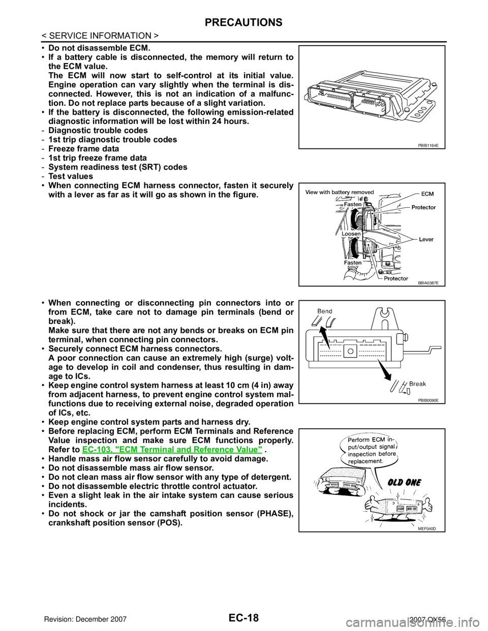
•When connecting ECM harness connector, fasten it securely
with a lever as far as it will go as shown in the figure.
•When connecting or disconnecting pin connectors into or
from ECM, take care not to damage pin terminals (bend or
break).
Make sure that there are not any bends or breaks on ECM pin
terminal, when connecting pin connectors.
•Securely connect ECM harness connectors.
A poor connection can cause an extremely high (surge) volt-
age to develop in coil and condenser, thus resulting in dam-
age to ICs.
•Keep engine control system harness at least 10 cm (4 in) away
from adjacent harness, to prevent engine control system mal-
functions due to receiving external noise, degraded operation
of ICs, etc.
•Keep engine control system parts and harness dry.
•Before replacing ECM, perform ECM Terminals and Reference
Value inspection and make sure ECM functions properly.
Refer to EC-103, "
ECM Terminal and Reference Value" .
•Handle mass air flow sensor carefully to avoid damage.
•Do not disassemble mass air flow sensor.
•Do not clean mass air flow sensor with any type of detergent.
•Do not disassemble electric throttle control actuator.
•Even a slight leak in the air intake system can cause serious
incidents.
•Do not shock or jar the camshaft position sensor (PHASE),
crankshaft position sensor (POS).
PBIB1164E
BBIA0387E
PBIB0090E
MEF040D
Page 1103 of 3061
EC-20
< SERVICE INFORMATION >
PRECAUTIONS
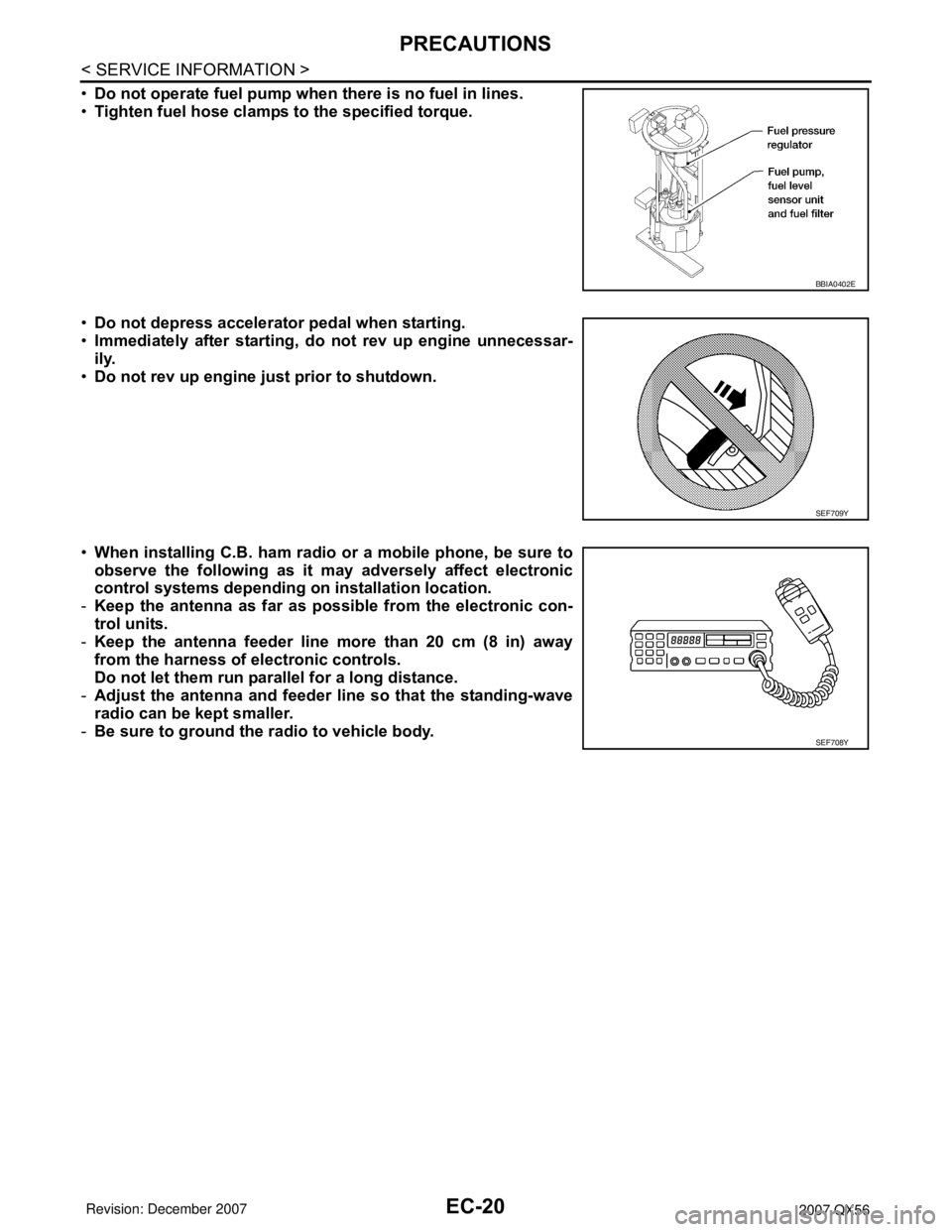
•Do not operate fuel pump when there is no fuel in lines.
•Tighten fuel hose clamps to the specified torque.
•Do not depress accelerator pedal when starting.
•Immediately after starting, do not rev up engine unnecessar-
ily.
•Do not rev up engine just prior to shutdown.
•When installing C.B. ham radio or a mobile phone, be sure to
observe the following as it may adversely affect electronic
control systems depending on installation location.
-Keep the antenna as far as possible from the electronic con-
trol units.
-Keep the antenna feeder line more than 20 cm (8 in) away
from the harness of electronic controls.
Do not let them run parallel for a long distance.
-Adjust the antenna and feeder line so that the standing-wave
radio can be kept smaller.
-Be sure to ground the radio to vehicle body.
BBIA0402E
SEF709Y
SEF708Y
Page 1105 of 3061
EC-22
< SERVICE INFORMATION >
PREPARATION
Commercial Service Tool
INFOID:0000000003531584
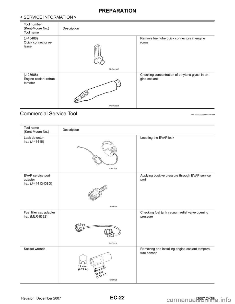
(J-45488)
Quick connector re-
leaseRemove fuel tube quick connectors in engine
room.
(J-23688)
Engine coolant refrac-
tometerChecking concentration of ethylene glycol in en-
gine coolant Tool number
(Kent-Moore No.)
Tool nameDescription
PBIC0198E
WBIA0539E
Tool name
(Kent-Moore No.)Description
Leak detector
i.e.: (J-41416)Locating the EVAP leak
EVAP service port
adapter
i.e.: (J-41413-OBD)Applying positive pressure through EVAP service
port
Fuel filler cap adapter
i.e.: (MLR-8382)Checking fuel tank vacuum relief valve opening
pressure
Socket wrench Removing and installing engine coolant tempera-
ture sensor
S-NT703
S-NT704
S-NT815
S-NT705
Page 1107 of 3061
EC-24
< SERVICE INFORMATION >
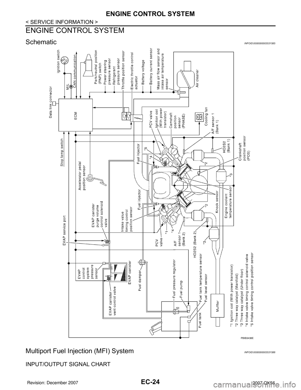
ENGINE CONTROL SYSTEM
ENGINE CONTROL SYSTEM
SchematicINFOID:0000000003531585
Multiport Fuel Injection (MFI) SystemINFOID:0000000003531586
INPUT/OUTPUT SIGNAL CHART
PBIB3438E