2007 INFINITI QX56 engine
[x] Cancel search: enginePage 1027 of 3061
DI-16
< SERVICE INFORMATION >
COMBINATION METERS
Perform self-diagnosis mode of combination meter. Refer to DI-12, "Self-Diagnosis Mode of Combination
Meter".
Does self-diagnosis mode operate normally?
YES >> GO TO 3.
NO >> Check combination meter power supply and ground circuit. Refer to DI-16, "
Power Supply and
Ground Circuit Inspection".
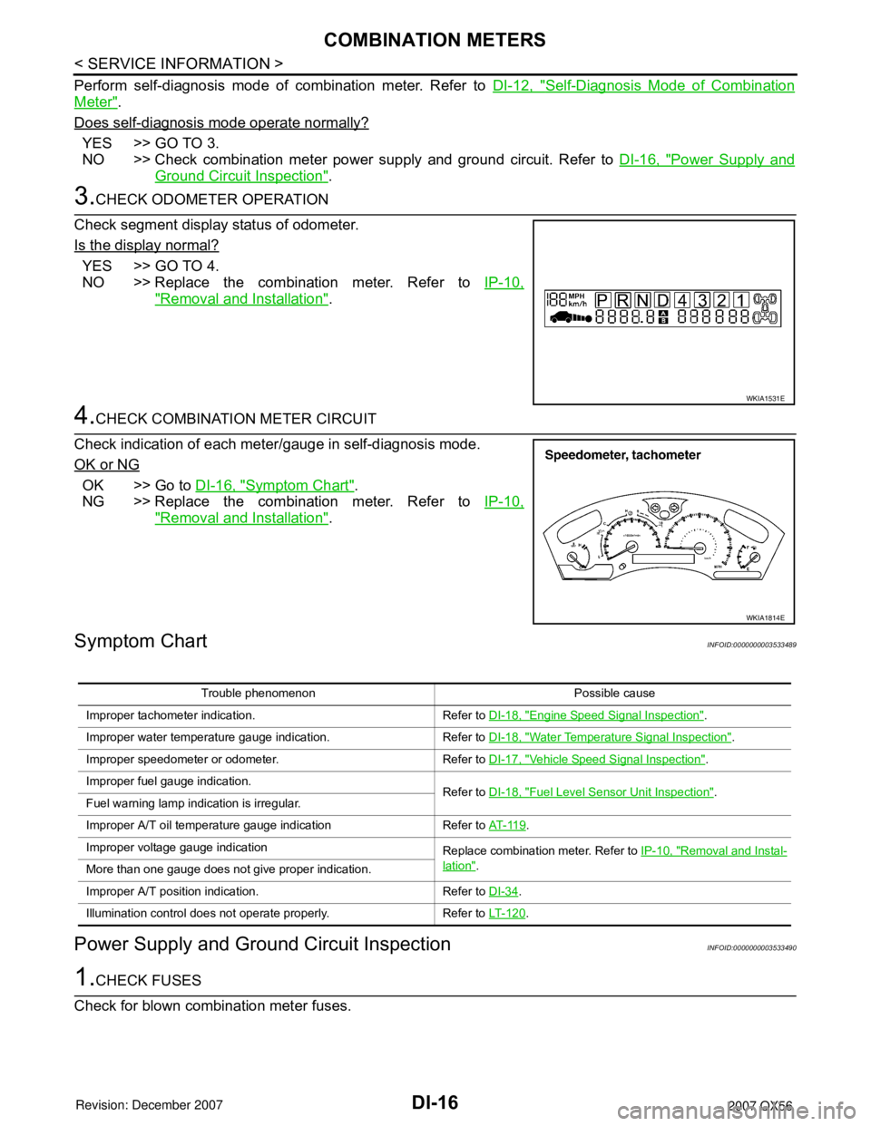
3.CHECK ODOMETER OPERATION
Check segment display status of odometer.
Is the display normal?
YES >> GO TO 4.
NO >> Replace the combination meter. Refer to IP-10,
"Removal and Installation".
4.CHECK COMBINATION METER CIRCUIT
Check indication of each meter/gauge in self-diagnosis mode.
OK or NG
OK >> Go to DI-16, "Symptom Chart".
NG >> Replace the combination meter. Refer to IP-10,
"Removal and Installation".
Symptom ChartINFOID:0000000003533489
Power Supply and Ground Circuit InspectionINFOID:0000000003533490
1.CHECK FUSES
Check for blown combination meter fuses.
WKIA1531E
WKIA1814E
Trouble phenomenon Possible cause
Improper tachometer indication. Refer to DI-18, "
Engine Speed Signal Inspection".
Improper water temperature gauge indication. Refer to DI-18, "
Water Temperature Signal Inspection".
Improper speedometer or odometer. Refer to DI-17, "
Vehicle Speed Signal Inspection".
Improper fuel gauge indication. Refer to DI-18, "
Fuel Level Sensor Unit Inspection".
Fuel warning lamp indication is irregular.
Improper A/T oil temperature gauge indication Refer to AT- 11 9
.
Improper voltage gauge indication Replace combination meter. Refer to IP-10, "
Removal and Instal-
lation".
More than one gauge does not give proper indication.
Improper A/T position indication. Refer to DI-34
.
Illumination control does not operate properly. Refer to LT- 1 2 0
.
Page 1028 of 3061
COMBINATION METERSDI-17
< SERVICE INFORMATION >
C
DE
F
G H
I
J
L
M A
B
DI
N
O P
Refer to DI-9, "Wiring Diagram - METER -".
OK or NG
OK >> GO TO 2.
NG >> If fuse is blown, be sure to eliminate caus e of malfunction before installing new fuse. Refer to PG-
3.
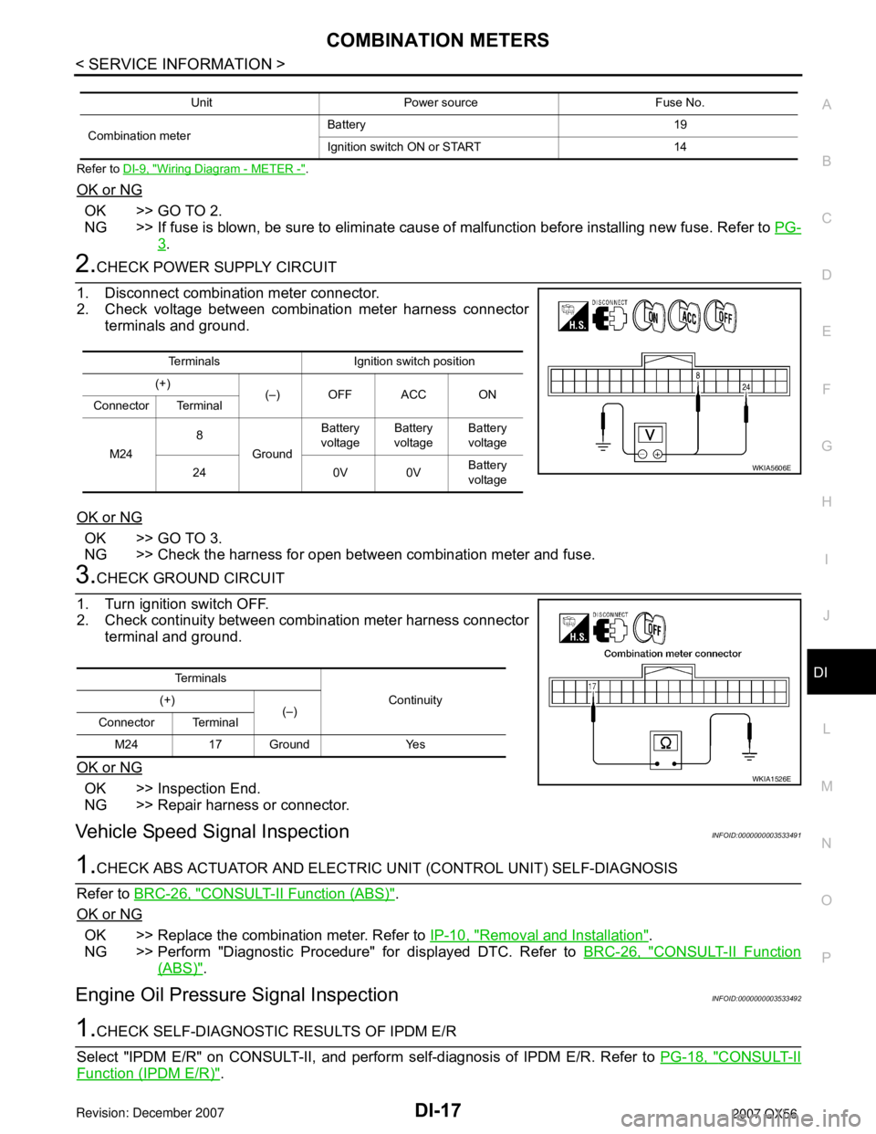
2.CHECK POWER SUPPLY CIRCUIT
1. Disconnect combination meter connector.
2. Check voltage between combination meter harness connector terminals and ground.
OK or NG
OK >> GO TO 3.
NG >> Check the harness for open between combination meter and fuse.
3.CHECK GROUND CIRCUIT
1. Turn ignition switch OFF.
2. Check continuity between combination meter harness connector terminal and ground.
OK or NG
OK >> Inspection End.
NG >> Repair harness or connector.
Vehicle Speed Signal InspectionINFOID:0000000003533491
1.CHECK ABS ACTUATOR AND ELECTRIC UNIT (CONTROL UNIT) SELF-DIAGNOSIS
Refer to BRC-26, "
CONSULT-II Function (ABS)".
OK or NG
OK >> Replace the combination meter. Refer to IP-10, "Removal and Installation".
NG >> Perform "Diagnostic Procedure" for displayed DTC. Refer to BRC-26, "
CONSULT-II Function
(ABS)".
Engine Oil Pressure Signal InspectionINFOID:0000000003533492
1.CHECK SELF-DIAGNOSTIC RESULTS OF IPDM E/R
Select "IPDM E/R" on CONSULT-II, and perform self-diagnosis of IPDM E/R. Refer to PG-18, "
CONSULT-II
Function (IPDM E/R)".
Unit Power source Fuse No.
Combination meter Battery 19
Ignition switch ON or START 14
Terminals Ignition switch position
(+) (–) OFF ACC ON
Connector Terminal
M24 8
Ground Battery
voltage Battery
voltage Battery
voltage
24 0V 0V Battery
voltage
WKIA5606E
Te r m i n a l s
Continuity
(+)
(–)
Connector Terminal
M24 17 Ground Yes
WKIA1526E
Page 1029 of 3061
DI-18
< SERVICE INFORMATION >
COMBINATION METERS
Self-diagnostic results content
No malfunction detected>>GO TO 2.
Malfunction detected>>GO TO PG-18, "
CONSULT-II Function (IPDM E/R)".
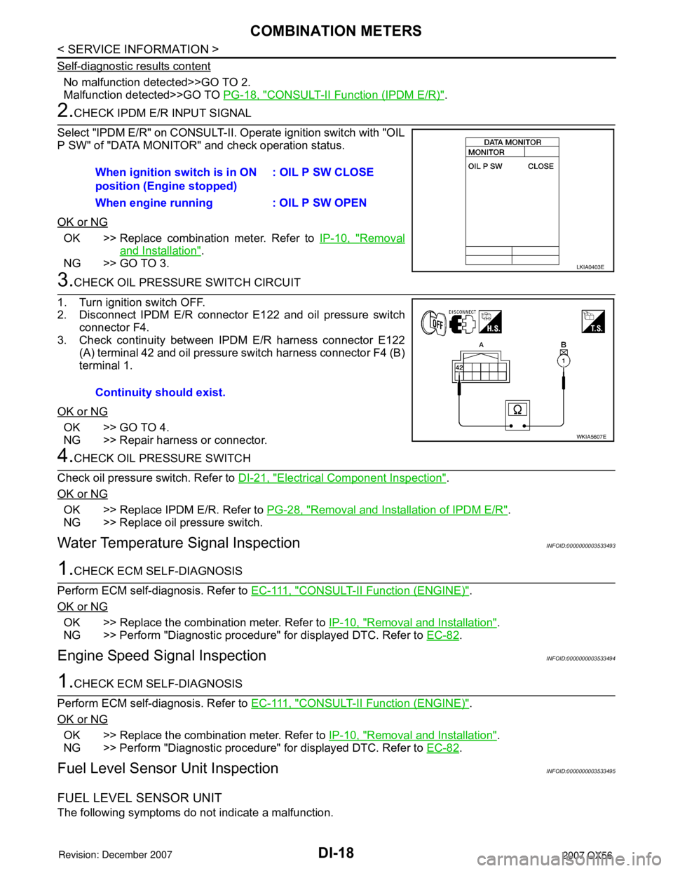
2.CHECK IPDM E/R INPUT SIGNAL
Select "IPDM E/R" on CONSULT-II. Operate ignition switch with "OIL
P SW" of "DATA MONITOR" and check operation status.
OK or NG
OK >> Replace combination meter. Refer to IP-10, "Removal
and Installation".
NG >> GO TO 3.
3.CHECK OIL PRESSURE SWITCH CIRCUIT
1. Turn ignition switch OFF.
2. Disconnect IPDM E/R connector E122 and oil pressure switch
connector F4.
3. Check continuity between IPDM E/R harness connector E122 (A) terminal 42 and oil pressure switch harness connector F4 (B)
terminal 1.
OK or NG
OK >> GO TO 4.
NG >> Repair harness or connector.
4.CHECK OIL PRESSURE SWITCH
Check oil pressure switch. Refer to DI-21, "
Electrical Component Inspection".
OK or NG
OK >> Replace IPDM E/R. Refer to PG-28, "Removal and Installation of IPDM E/R".
NG >> Replace oil pressure switch.
Water Temperature Signal InspectionINFOID:0000000003533493
1.CHECK ECM SELF-DIAGNOSIS
Perform ECM self-diagnosis. Refer to E C - 111 , "
CONSULT-II Function (ENGINE)".
OK or NG
OK >> Replace the combination meter. Refer to IP-10, "Removal and Installation".
NG >> Perform "Diagnostic procedure" for displayed DTC. Refer to EC-82
.
Engine Speed Signal InspectionINFOID:0000000003533494
1.CHECK ECM SELF-DIAGNOSIS
Perform ECM self-diagnosis. Refer to E C - 111 , "
CONSULT-II Function (ENGINE)".
OK or NG
OK >> Replace the combination meter. Refer to IP-10, "Removal and Installation".
NG >> Perform "Diagnostic procedure" for displayed DTC. Refer to EC-82
.
Fuel Level Sensor Unit InspectionINFOID:0000000003533495
FUEL LEVEL SENSOR UNIT
The following symptoms do not indicate a malfunction.When ignition switch is in ON
position (Engine stopped)
: OIL P SW CLOSE
When engine running : OIL P SW OPEN
LKIA0403E
Continuity should exist.
WKIA5607E
Page 1032 of 3061
COMBINATION METERS
DI-21
< SERVICE INFORMATION >
C
D
E
F
G
H
I
J
L
MA
B
DI
N
O
P
4.CHECK POINTER MOVEMENT TO EMPTY-POSITION
During driving, does the fuel gauge move gradually toward empty-position?
YES or NO
YES >> Check the fuel level sensor unit. Refer to DI-21, "Electrical Component Inspection".
NO >> Check fuel level sensor unit installation, and determine whether the float arm interferes or binds
with any of the internal components in the fuel tank.
Electrical Component InspectionINFOID:0000000003533498
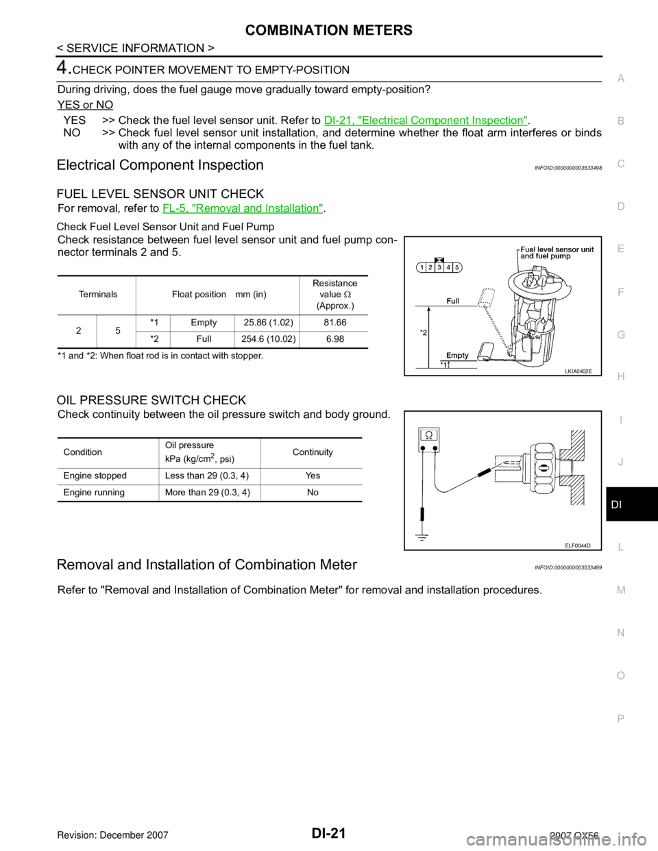
FUEL LEVEL SENSOR UNIT CHECK
For removal, refer to FL-5, "Removal and Installation".
Check Fuel Level Sensor Unit and Fuel Pump
Check resistance between fuel level sensor unit and fuel pump con-
nector terminals 2 and 5.
*1 and *2: When float rod is in contact with stopper.
OIL PRESSURE SWITCH CHECK
Check continuity between the oil pressure switch and body ground.
Removal and Installation of Combination MeterINFOID:0000000003533499
Refer to "Removal and Installation of Combination Meter" for removal and installation procedures.
Terminals Float position mm (in)Resistance
value Ω
(Approx.)
25*1 Empty 25.86 (1.02) 81.66
*2 Full 254.6 (10.02) 6.98
LKIA0402E
ConditionOil pressure
kPa (kg/cm2, psi)Continuity
Engine stopped Less than 29 (0.3, 4) Yes
Engine running More than 29 (0.3, 4) No
ELF0044D
Page 1044 of 3061
WARNING LAMPS
DI-33
< SERVICE INFORMATION >
C
D
E
F
G
H
I
J
L
MA
B
DI
N
O
P
No malfunction detected>>GO TO 2.
Malfunction detected>>GO TO PG-18, "
CONSULT-II Function (IPDM E/R)".
2.CHECK IPDM E/R INPUT SIGNAL
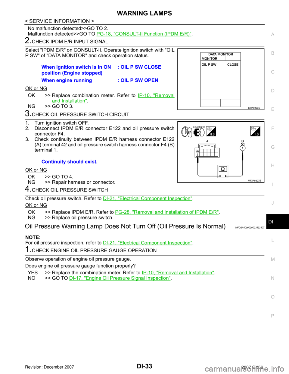
Select "IPDM E/R" on CONSULT-II. Operate ignition switch with "OIL
P SW" of "DATA MONITOR" and check operation status.
OK or NG
OK >> Replace combination meter. Refer to IP-10, "Removal
and Installation".
NG >> GO TO 3.
3.CHECK OIL PRESSURE SWITCH CIRCUIT
1. Turn ignition switch OFF.
2. Disconnect IPDM E/R connector E122 and oil pressure switch
connector F4.
3. Check continuity between IPDM E/R harness connector E122
(A) terminal 42 and oil pressure switch harness connector F4 (B)
terminal 1.
OK or NG
OK >> GO TO 4.
NG >> Repair harness or connector.
4.CHECK OIL PRESSURE SWITCH
Check oil pressure switch. Refer to DI-21, "
Electrical Component Inspection".
OK or NG
OK >> Replace IPDM E/R. Refer to PG-28, "Removal and Installation of IPDM E/R".
NG >> Replace oil pressure switch.
Oil Pressure Warning Lamp Does Not Turn Off (Oil Pressure Is Normal)INFOID:0000000003533507
NOTE:
For oil pressure inspection, refer to DI-21, "
Electrical Component Inspection".
1.CHECK ENGINE OIL PRESSURE GAUGE OPERATION
Observe operation of engine oil pressure gauge.
Does engine oil pressure gauge function properly?
YES >> Replace the combination meter. Refer to IP-10, "Removal and Installation".
NO >> GO TO DI-17, "
Engine Oil Pressure Signal Inspection". When ignition switch is in ON
position (Engine stopped): OIL P SW CLOSE
When engine running : OIL P SW OPEN
LKIA0403E
Continuity should exist.
WKIA5607E
Page 1062 of 3061
REAR SONAR SYSTEM
DI-51
< SERVICE INFORMATION >
C
D
E
F
G
H
I
J
L
MA
B
DI
N
O
P
How to Proceed with Trouble DiagnosisINFOID:0000000003533529
1. Confirm the symptom or customer complaint.
2. Understand operation description and function description. Refer to DI-46, "
System Description".
3. Perform pre-diagnosis inspection. Refer to DI-51, "
Pre-diagnosis Inspection".
4. Perform self-diagnosis. Refer to DI-51, "
Self-Diagnosis Function".
5. Perform the preliminary check. Refer to DI-53, "
Preliminary Check".
6. Check symptom and repair or replace the cause of malfunction. Refer to DI-54, "
Symptom Chart".
7. Does the rear sonar system operate properly? If so, go to 8. If not, go to 3.
8. Clear fault codes. Refer to DI-51, "
Self-Diagnosis Function".
9. Inspection End.
Pre-diagnosis InspectionINFOID:0000000003533530
SENSOR STATUS CHECK
• Check that the rear sonar sensor is properly aligned (bumper is not misaligned, no deformation in sensor
mounting area.
• Check that snow, mud, or other foreign objects are not adhering to the rear sonar sensor.
• Check that there is no deformation, scratches, or other damage to the rear sonar sensor.
• Check that water has not accumulated in the rear sonar sensor.
CAUTION:
Use water, cotton swab, or other soft material for cleaning the sensor.
1. Check that there are no obstacles within each rear sonar sensor's detection range.
2. Check that there are no nearby ultrasound sources (such as the sounds of vehicle horns, motorcycle
engines, or truck air brakes).
3. Check that the vehicle is on a level surface.
Self-Diagnosis FunctionINFOID:0000000003533531
There are four modes of self-diagnosis; entering diagnostics, requesting number of fault codes, requesting
fault codes, and idling or clearing fault codes. These steps must be followed in order. Self-diagnosis can be
manually exited by turning the ignition switch OFF, or selecting reverse gear. Self-diagnosis will exit unless a
fault code request occurs before a message is repeated five times without acknowledgement.
ENTERING DIAGNOSTICS MODE
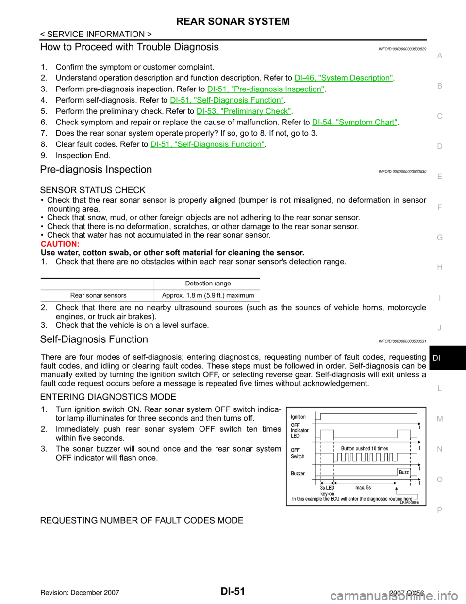
1. Turn ignition switch ON. Rear sonar system OFF switch indica-
tor lamp illuminates for three seconds and then turns off.
2. Immediately push rear sonar system OFF switch ten times
within five seconds.
3. The sonar buzzer will sound once and the rear sonar system
OFF indicator will flash once.
REQUESTING NUMBER OF FAULT CODES MODE
Detection range
Rear sonar sensors Approx. 1.8 m (5.9 ft.) maximum
LKIA0389E
Page 1076 of 3061
REAR VIEW MONITOR
DI-65
< SERVICE INFORMATION >
C
D
E
F
G
H
I
J
L
MA
B
DI
N
O
P
CONSULT-II START PROCEDURE
Refer to GI-36, "CONSULT-II Start Procedure".
WORK SUPPORT
Refer to DI-65, "Side Distance Guideline Correction" for details.
DATA MONITOR
Display Item List
Side Distance Guideline CorrectionINFOID:0000000003533545
This mode is used to modify the side distance guidelines if they are dislocated from the rear view monitor
image, because of variations of body/camera mounting conditions.
SIDE DISTANCE GUIDELINE CORRECTION PROCEDURE
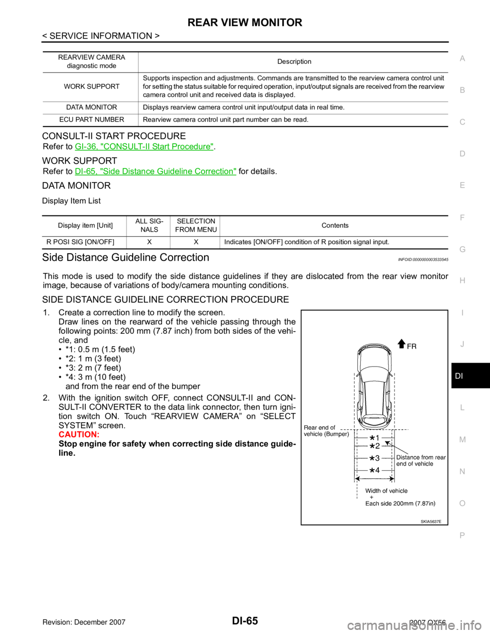
1. Create a correction line to modify the screen.
Draw lines on the rearward of the vehicle passing through the
following points: 200 mm (7.87 inch) from both sides of the vehi-
cle, and
• *1: 0.5 m (1.5 feet)
• *2: 1 m (3 feet)
• *3: 2 m (7 feet)
• *4: 3 m (10 feet)
and from the rear end of the bumper
2. With the ignition switch OFF, connect CONSULT-II and CON-
SULT-II CONVERTER to the data link connector, then turn igni-
tion switch ON. Touch “REARVIEW CAMERA” on “SELECT
SYSTEM” screen.
CAUTION:
Stop engine for safety when correcting side distance guide-
line.
REARVIEW CAMERA
diagnostic modeDescription
WORK SUPPORTSupports inspection and adjustments. Commands are transmitted to the rearview camera control unit
for setting the status suitable for required operation, input/output signals are received from the rearview
camera control unit and received data is displayed.
DATA MONITOR Displays rearview camera control unit input/output data in real time.
ECU PART NUMBER Rearview camera control unit part number can be read.
Display item [Unit]ALL SIG-
NALSSELECTION
FROM MENUContents
R POSI SIG [ON/OFF] X X Indicates [ON/OFF] condition of R position signal input.
SKIA5637E
Page 1084 of 3061

EC-1
ENGINE
C
D
E
F
G
H
I
J
K
L
M
SECTION EC
A
EC
N
O
P
CONTENTS
ENGINE CONTROL SYSTEM
SERVICE INFORMATION ............................9
INDEX FOR DTC .................................................9
DTC No. Index ..........................................................9
Alphabetical Index ...................................................12
PRECAUTIONS ..................................................17
Precaution for Supplemental Restraint System
(SRS) "AIR BAG" and "SEAT BELT PRE-TEN-
SIONER" .................................................................
17
On Board Diagnosis (OBD) System of Engine and
A/T ...........................................................................
17
Precaution ...............................................................17
PREPARATION ..................................................21
Special Service Tool ...............................................21
Commercial Service Tool ........................................22
ENGINE CONTROL SYSTEM ............................24
Schematic ...............................................................24
Multiport Fuel Injection (MFI) System .....................24
Electronic Ignition (EI) System ................................27
Fuel Cut Control (at No Load and High Engine
Speed) .....................................................................
27
AIR CONDITIONING CUT CONTROL ...............29
Input/Output Signal Chart ........................................29
System Description .................................................29
AUTOMATIC SPEED CONTROL DEVICE
(ASCD) ...............................................................
30
System Description .................................................30
Component Description ...........................................31
CAN COMMUNICATION ....................................32
System Description .................................................32
EVAPORATIVE EMISSION SYSTEM ................33
Description ..............................................................33
Component Inspection ............................................35
Removal and Installation .........................................37
How to Detect Fuel Vapor Leakage ........................37
ON BOARD REFUELING VAPOR RECOV-
ERY (ORVR) ......................................................
40
System Description ..................................................40
Diagnosis Procedure ...............................................40
Component Inspection .............................................42
POSITIVE CRANKCASE VENTILATION .........45
Description ...............................................................45
Component Inspection .............................................45
IVIS (INFINITI VEHICLE IMMOBILIZER SYS-
TEM-NATS) .......................................................
47
Description ...............................................................47
ON BOARD DIAGNOSTIC (OBD) SYSTEM ....48
Introduction ..............................................................48
Two Trip Detection Logic .........................................48
Emission-related Diagnostic Information .................49
Malfunction Indicator Lamp (MIL) ............................63
OBD System Operation Chart .................................65
BASIC SERVICE PROCEDURE .......................71
Basic Inspection ......................................................71
Idle Speed and Ignition Timing Check .....................75
Procedure After Replacing ECM .............................77
VIN Registration ......................................................77
Accelerator Pedal Released Position Learning .......77
Throttle Valve Closed Position Learning .................77
Idle Air Volume Learning .........................................78
Fuel Pressure Check ...............................................80
TROUBLE DIAGNOSIS ....................................82
Trouble Diagnosis Introduction ................................82
DTC Inspection Priority Chart ..................................87
Fail-Safe Chart ........................................................88
Symptom Matrix Chart .............................................90
Engine Control Component Parts Location .............94
Vacuum Hose Drawing ..........................................100
Circuit Diagram ......................................................101
ECM Harness Connector Terminal Layout ............103
ECM Terminal and Reference Value .....................103