2007 INFINITI QX56 engine
[x] Cancel search: enginePage 1123 of 3061
EC-40
< SERVICE INFORMATION >
ON BOARD REFUELING VAPOR RECOVERY (ORVR)
ON BOARD REFUELING VAPOR RECOVERY (ORVR)
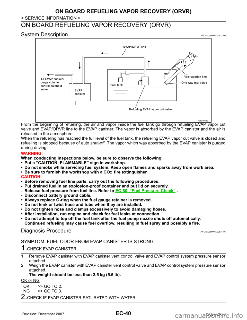
System DescriptionINFOID:0000000003531598
From the beginning of refueling, the air and vapor inside the fuel tank go through refueling EVAP vapor cut
valve and EVAP/ORVR line to the EVAP canister. The vapor is absorbed by the EVAP canister and the air is
released to the atmosphere.
When the refueling has reached the full level of the fuel tank, the refueling EVAP vapor cut valve is closed and
refueling is stopped because of auto shut-off. The vapor which was absorbed by the EVAP canister is purged
during driving.
WARNING:
When conducting inspections below, be sure to observe the following:
• Put a “CAUTION: FLAMMABLE” sign in workshop.
• Do not smoke while servicing fuel system. Keep open flames and sparks away from work area.
• Be sure to furnish the workshop with a CO
2 fire extinguisher.
CAUTION:
• Before removing fuel line parts, carry out the following procedures:
- Put drained fuel in an explosion-proof container and put lid on securely.
- Release fuel pressure from fuel line. Refer to EC-80, "
Fuel Pressure Check" .
- Disconnect battery ground cable.
• Always replace O-ring when the fuel gauge retainer is removed.
• Do not kink or twist hose and tube when they are installed.
• Do not tighten hose and clamps excessively to avoid damaging hoses.
• After installation, run engine and check for fuel leaks at connection.
• Do not attempt to top off the fuel tank after the fuel pump nozzle shuts off automatically.
Continued refueling may cause fuel overflow, resulting in fuel spray and possibly a fire.
Diagnosis ProcedureINFOID:0000000003531599
SYMPTOM: FUEL ODOR FROM EVAP CANISTER IS STRONG.
1.CHECK EVAP CANISTER
1. Remove EVAP canister with EVAP canister vent control valve and EVAP control system pressure sensor
attached.
2. Weigh the EVAP canister with EVAP canister vent control valve and EVAP control system pressure sensor
attached.
The weight should be less than 2.5 kg (5.5 lb).
OK or NG
OK >> GO TO 2.
NG >> GO TO 3.
2.CHECK IF EVAP CANISTER SATURATED WITH WATER
PBIB1068E
Page 1128 of 3061
POSITIVE CRANKCASE VENTILATION
EC-45
< SERVICE INFORMATION >
C
D
E
F
G
H
I
J
K
L
MA
EC
N
P O
POSITIVE CRANKCASE VENTILATION
DescriptionINFOID:0000000003531601
SYSTEM DESCRIPTION
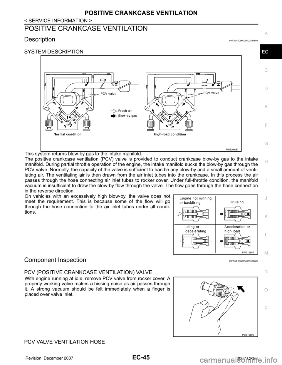
This system returns blow-by gas to the intake manifold.
The positive crankcase ventilation (PCV) valve is provided to conduct crankcase blow-by gas to the intake
manifold. During partial throttle operation of the engine, the intake manifold sucks the blow-by gas through the
PCV valve. Normally, the capacity of the valve is sufficient to handle any blow-by and a small amount of venti-
lating air. The ventilating air is then drawn from the air inlet tubes into the crankcase. In this process the air
passes through the hose connecting air inlet tubes to rocker cover. Under full-throttle condition, the manifold
vacuum is insufficient to draw the blow-by flow through the valve. The flow goes through the hose connection
in the reverse direction.
On vehicles with an excessively high blow-by, the valve does not
meet the requirement. This is because some of the flow will go
through the hose connection to the air inlet tubes under all condi-
tions.
Component InspectionINFOID:0000000003531602
PCV (POSITIVE CRANKCASE VENTILATION) VALVE
With engine running at idle, remove PCV valve from rocker cover. A
properly working valve makes a hissing noise as air passes through
it. A strong vacuum should be felt immediately when a finger is
placed over valve inlet.
PCV VALVE VENTILATION HOSE
PBIB0062E
PBIB1588E
PBIB1589E
Page 1131 of 3061

EC-48
< SERVICE INFORMATION >
ON BOARD DIAGNOSTIC (OBD) SYSTEM
ON BOARD DIAGNOSTIC (OBD) SYSTEM
IntroductionINFOID:0000000003531604
The ECM has an on board diagnostic system, which detects malfunctions related to engine sensors or actua-
tors. The ECM also records various emission-related diagnostic information including:
The above information can be checked using procedures listed in the table below.
×: Applicable —: Not applicable
*: When DTC and 1st trip DTC simultaneously appear on the display, they cannot be clearly distinguished from each other.
The malfunction indicator lamp (MIL) on the instrument panel lights up when the same malfunction is detected
in two consecutive trips (Two trip detection logic), or when the ECM enters fail-safe mode. (Refer to EC-88,
"Fail-Safe Chart".)
Two Trip Detection LogicINFOID:0000000003531605
When a malfunction is detected for the first time, 1st trip DTC and 1st trip Freeze Frame data are stored in the
ECM memory. The MIL will not light up at this stage. <1st trip>
If the same malfunction is detected again during the next drive, the DTC and Freeze Frame data are stored in
the ECM memory, and the MIL lights up. The MIL lights up at the same time when the DTC is stored. <2nd
trip> The “trip” in the “Two Trip Detection Logic” means a driving mode in which self-diagnosis is performed
during vehicle operation. Specific on board diagnostic items will cause the ECM to light up or blink the MIL,
and store DTC and Freeze Frame data, even in the 1st trip, as shown below.
×: Applicable —: Not applicable
When there is an open circuit on MIL circuit, the ECM cannot warn the driver by lighting up MIL when there is
malfunction on engine control system.
Emission-related diagnostic information Diagnostic service
Diagnostic Trouble Code (DTC) Service $03 of SAE J1979
Freeze Frame data Service $02 of SAE J1979
System Readiness Test (SRT) code Service $01 of SAE J1979
1st Trip Diagnostic Trouble Code (1st Trip DTC) Service $07 of SAE J1979
1st Trip Freeze Frame data
Test values and Test limits Service $06 of SAE J1979
Calibration ID Service $09 of SAE J1979
DTC 1st trip DTCFreeze
Frame data1st trip Freeze
Frame dataSRT code SRT status Test value
CONSULT-II×× × × × ×—
GST×× ×—×××
ECM××*— — —×—
ItemsMIL DTC 1st trip DTC
1st trip 2nd trip
1st trip
displaying2nd trip
displaying1st trip
displaying2nd trip
display-
ing BlinkingLighting
upBlinkingLighting
up
Misfire (Possible three way catalyst
damage) — DTC: P0300 - P0308 is
being detected×———— —×—
Misfire (Possible three way catalyst
damage) — DTC: P0300 - P0308 is
being detected——×——×——
One trip detection diagnoses (Re-
fer to EC-49, "
Emission-related Di-
agnostic Information".)—×——×———
Except above — — —×—××—
Page 1132 of 3061
ON BOARD DIAGNOSTIC (OBD) SYSTEM
EC-49
< SERVICE INFORMATION >
C
D
E
F
G
H
I
J
K
L
MA
EC
N
P O
Therefore, when electrical controlled throttle and part of ECM related diagnoses are continuously detected as
NG for 5 trips, ECM warns the driver that engine control system malfunctions and MIL circuit is open by means
of operating fail-safe function.
The fail-safe function also operates when above diagnoses except MIL circuit are detected and demands the
driver to repair the malfunction.
Emission-related Diagnostic InformationINFOID:0000000003531606
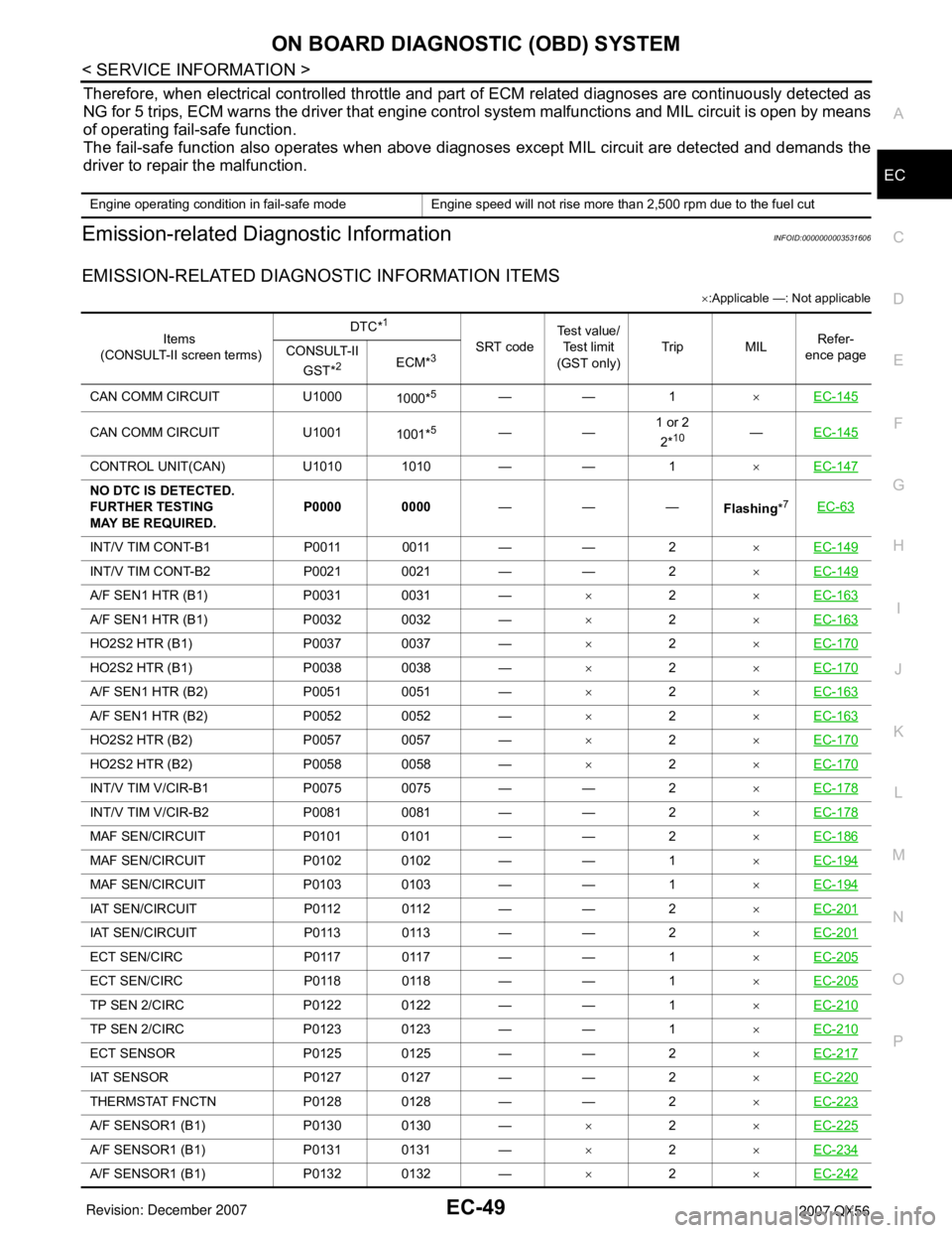
EMISSION-RELATED DIAGNOSTIC INFORMATION ITEMS
×:Applicable —: Not applicable
Engine operating condition in fail-safe mode Engine speed will not rise more than 2,500 rpm due to the fuel cut
Items
(CONSULT-II screen terms)DTC*
1
SRT codeTe s t v a l u e /
Test limit
(GST only)Trip MILRefer-
ence page CONSULT-II
GST*
2ECM*3
CAN COMM CIRCUIT U1000
1000*5—— 1×EC-145
CAN COMM CIRCUIT U1001
1001*5——1 or 2
2*10—EC-145
CONTROL UNIT(CAN) U1010 1010 — — 1×EC-147
NO DTC IS DETECTED.
FURTHER TESTING
MAY BE REQUIRED.P0000 0000———
Flashing*7EC-63
INT/V TIM CONT-B1 P0011 0011 — — 2×EC-149
INT/V TIM CONT-B2 P0021 0021 — — 2×EC-149
A/F SEN1 HTR (B1) P0031 0031 —×2×EC-163
A/F SEN1 HTR (B1) P0032 0032 —×2×EC-163
HO2S2 HTR (B1) P0037 0037 —×2×EC-170
HO2S2 HTR (B1) P0038 0038 —×2×EC-170
A/F SEN1 HTR (B2) P0051 0051 —×2×EC-163
A/F SEN1 HTR (B2) P0052 0052 —×2×EC-163
HO2S2 HTR (B2) P0057 0057 —×2×EC-170
HO2S2 HTR (B2) P0058 0058 —×2×EC-170
INT/V TIM V/CIR-B1 P0075 0075 — — 2×EC-178
INT/V TIM V/CIR-B2 P0081 0081 — — 2×EC-178
MAF SEN/CIRCUIT P0101 0101 — — 2×EC-186
MAF SEN/CIRCUIT P0102 0102 — — 1×EC-194
MAF SEN/CIRCUIT P0103 0103 — — 1×EC-194
IAT SEN/CIRCUIT P0112 0112 — — 2×EC-201
IAT SEN/CIRCUIT P0113 0113 — — 2×EC-201
ECT SEN/CIRC P0117 0117 — — 1×EC-205
ECT SEN/CIRC P0118 0118 — — 1×EC-205
TP SEN 2/CIRC P0122 0122 — — 1×EC-210
TP SEN 2/CIRC P0123 0123 — — 1×EC-210
ECT SENSOR P0125 0125 — — 2×EC-217
IAT SENSOR P0127 0127 — — 2×EC-220
THERMSTAT FNCTN P0128 0128 — — 2×EC-223
A/F SENSOR1 (B1) P0130 0130 —×2×EC-225
A/F SENSOR1 (B1) P0131 0131 —×2×EC-234
A/F SENSOR1 (B1) P0132 0132 —×2×EC-242
Page 1137 of 3061
EC-54
< SERVICE INFORMATION >
ON BOARD DIAGNOSTIC (OBD) SYSTEM
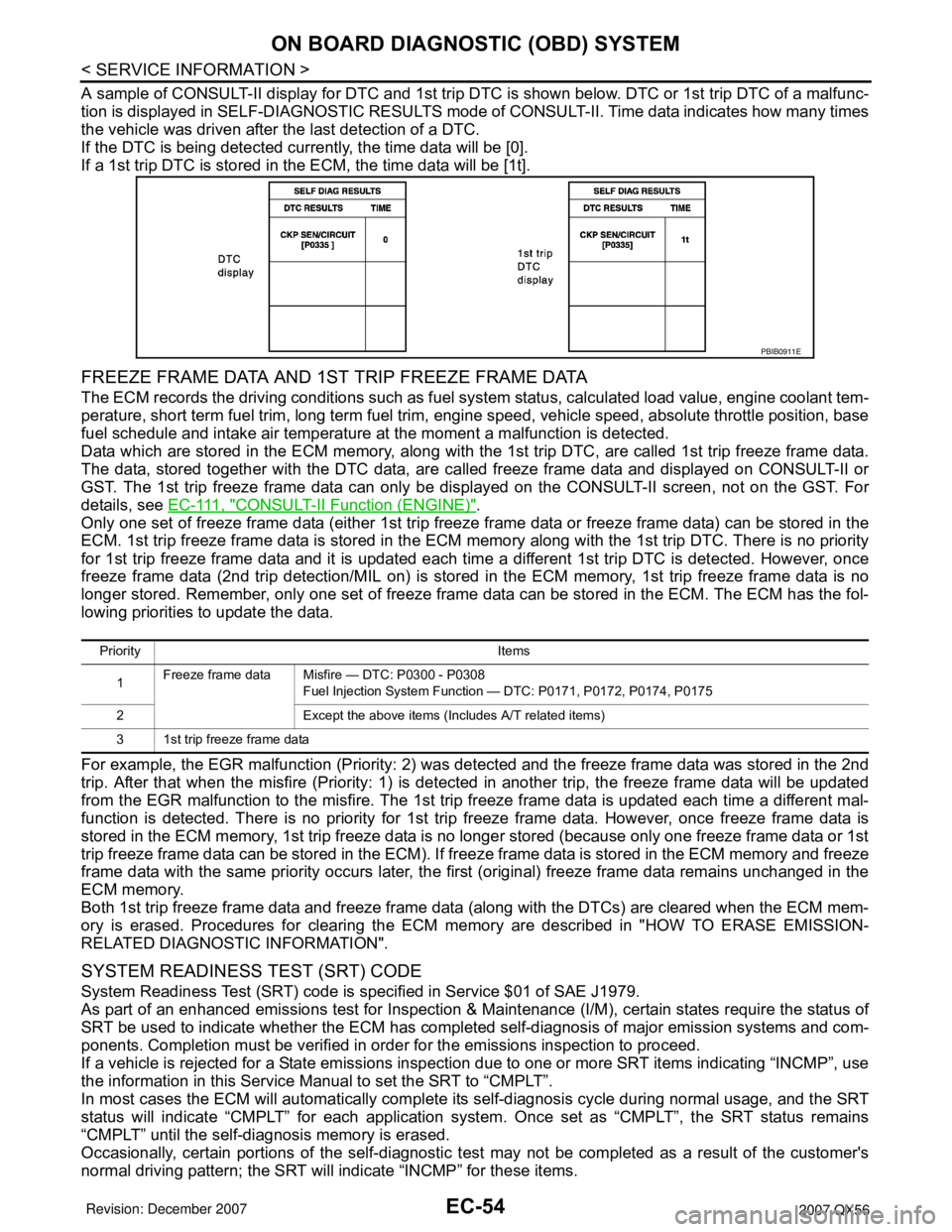
A sample of CONSULT-II display for DTC and 1st trip DTC is shown below. DTC or 1st trip DTC of a malfunc-
tion is displayed in SELF-DIAGNOSTIC RESULTS mode of CONSULT-II. Time data indicates how many times
the vehicle was driven after the last detection of a DTC.
If the DTC is being detected currently, the time data will be [0].
If a 1st trip DTC is stored in the ECM, the time data will be [1t].
FREEZE FRAME DATA AND 1ST TRIP FREEZE FRAME DATA
The ECM records the driving conditions such as fuel system status, calculated load value, engine coolant tem-
perature, short term fuel trim, long term fuel trim, engine speed, vehicle speed, absolute throttle position, base
fuel schedule and intake air temperature at the moment a malfunction is detected.
Data which are stored in the ECM memory, along with the 1st trip DTC, are called 1st trip freeze frame data.
The data, stored together with the DTC data, are called freeze frame data and displayed on CONSULT-II or
GST. The 1st trip freeze frame data can only be displayed on the CONSULT-II screen, not on the GST. For
details, see E C - 111 , "
CONSULT-II Function (ENGINE)".
Only one set of freeze frame data (either 1st trip freeze frame data or freeze frame data) can be stored in the
ECM. 1st trip freeze frame data is stored in the ECM memory along with the 1st trip DTC. There is no priority
for 1st trip freeze frame data and it is updated each time a different 1st trip DTC is detected. However, once
freeze frame data (2nd trip detection/MIL on) is stored in the ECM memory, 1st trip freeze frame data is no
longer stored. Remember, only one set of freeze frame data can be stored in the ECM. The ECM has the fol-
lowing priorities to update the data.
For example, the EGR malfunction (Priority: 2) was detected and the freeze frame data was stored in the 2nd
trip. After that when the misfire (Priority: 1) is detected in another trip, the freeze frame data will be updated
from the EGR malfunction to the misfire. The 1st trip freeze frame data is updated each time a different mal-
function is detected. There is no priority for 1st trip freeze frame data. However, once freeze frame data is
stored in the ECM memory, 1st trip freeze data is no longer stored (because only one freeze frame data or 1st
trip freeze frame data can be stored in the ECM). If freeze frame data is stored in the ECM memory and freeze
frame data with the same priority occurs later, the first (original) freeze frame data remains unchanged in the
ECM memory.
Both 1st trip freeze frame data and freeze frame data (along with the DTCs) are cleared when the ECM mem-
ory is erased. Procedures for clearing the ECM memory are described in "HOW TO ERASE EMISSION-
RELATED DIAGNOSTIC INFORMATION".
SYSTEM READINESS TEST (SRT) CODE
System Readiness Test (SRT) code is specified in Service $01 of SAE J1979.
As part of an enhanced emissions test for Inspection & Maintenance (I/M), certain states require the status of
SRT be used to indicate whether the ECM has completed self-diagnosis of major emission systems and com-
ponents. Completion must be verified in order for the emissions inspection to proceed.
If a vehicle is rejected for a State emissions inspection due to one or more SRT items indicating “INCMP”, use
the information in this Service Manual to set the SRT to “CMPLT”.
In most cases the ECM will automatically complete its self-diagnosis cycle during normal usage, and the SRT
status will indicate “CMPLT” for each application system. Once set as “CMPLT”, the SRT status remains
“CMPLT” until the self-diagnosis memory is erased.
Occasionally, certain portions of the self-diagnostic test may not be completed as a result of the customer's
normal driving pattern; the SRT will indicate “INCMP” for these items.
PBIB0911E
Priority Items
1Freeze frame data Misfire — DTC: P0300 - P0308
Fuel Injection System Function — DTC: P0171, P0172, P0174, P0175
2 Except the above items (Includes A/T related items)
3 1st trip freeze frame data
Page 1143 of 3061
EC-60
< SERVICE INFORMATION >
ON BOARD DIAGNOSTIC (OBD) SYSTEM
• Sea level
• Flat road
• Ambient air temperature: 20 - 30°C (68 - 86°F)
• Diagnosis is performed as quickly as possible under normal conditions.
Under different conditions [For example: ambient air temperature other than 20 - 30°C (68 - 86°F)], diagno-
sis may also be performed.
Pattern 1:
•The engine is started at the engine coolant temperature of −10 to 35°C (14 to 95°F)
(where the voltage between the ECM terminal 73 and ground is 3.0 - 4.3V).
•The engine must be operated at idle speed until the engine coolant temperature is greater than 70°C
(158°F) (where the voltage between the ECM terminal 73 and ground is lower than 1.4V).
•The engine is started at the fuel tank temperature of warmer than 0°C (32°F) (where the voltage
between the ECM terminal 107 and ground is less than 4.1V).
Pattern 2:
• When steady-state driving is performed again even after it is interrupted, each diagnosis can be conducted.
In this case, the time required for diagnosis may be extended.
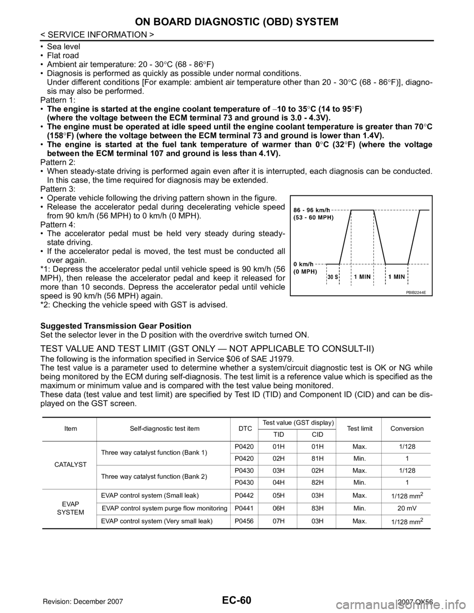
Pattern 3:
• Operate vehicle following the driving pattern shown in the figure.
• Release the accelerator pedal during decelerating vehicle speed
from 90 km/h (56 MPH) to 0 km/h (0 MPH).
Pattern 4:
• The accelerator pedal must be held very steady during steady-
state driving.
• If the accelerator pedal is moved, the test must be conducted all
over again.
*1: Depress the accelerator pedal until vehicle speed is 90 km/h (56
MPH), then release the accelerator pedal and keep it released for
more than 10 seconds. Depress the accelerator pedal until vehicle
speed is 90 km/h (56 MPH) again.
*2: Checking the vehicle speed with GST is advised.
Suggested Transmission Gear Position
Set the selector lever in the D position with the overdrive switch turned ON.
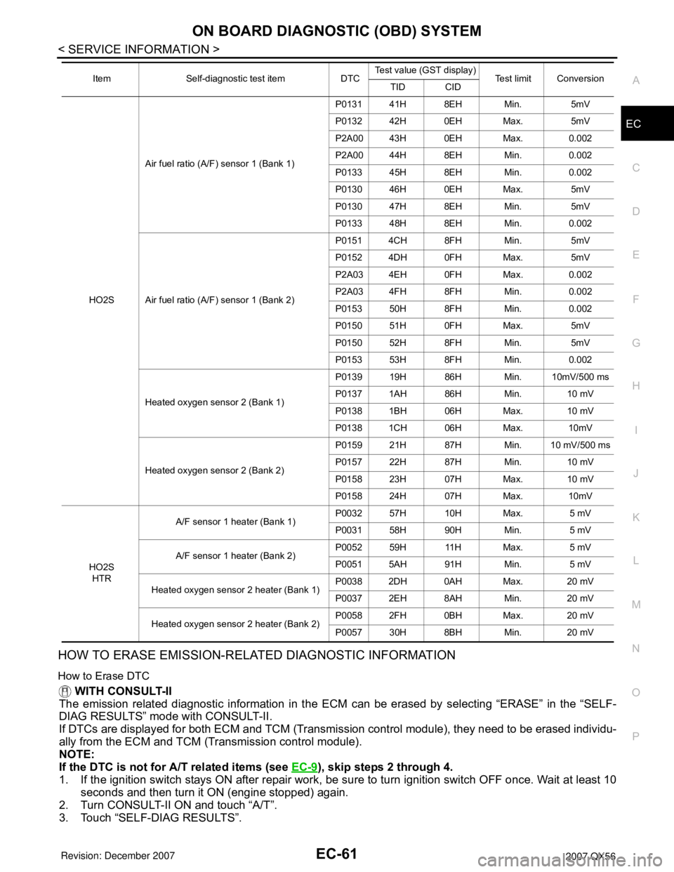
TEST VALUE AND TEST LIMIT (GST ONLY — NOT APPLICABLE TO CONSULT-II)
The following is the information specified in Service $06 of SAE J1979.
The test value is a parameter used to determine whether a system/circuit diagnostic test is OK or NG while
being monitored by the ECM during self-diagnosis. The test limit is a reference value which is specified as the
maximum or minimum value and is compared with the test value being monitored.
These data (test value and test limit) are specified by Test ID (TID) and Component ID (CID) and can be dis-
played on the GST screen.
PBIB2244E
Item Self-diagnostic test item DTCTest value (GST display)
Test limit Conversion
TID CID
CATALYSTThree way catalyst function (Bank 1)P0420 01H 01H Max. 1/128
P0420 02H 81H Min. 1
Three way catalyst function (Bank 2)P0430 03H 02H Max. 1/128
P0430 04H 82H Min. 1
EVAP
SYSTEMEVAP control system (Small leak) P0442 05H 03H Max.
1/128 mm
2
EVAP control system purge flow monitoring P0441 06H 83H Min. 20 mV
EVAP control system (Very small leak) P0456 07H 03H Max.
1/128 mm
2
Page 1144 of 3061
ON BOARD DIAGNOSTIC (OBD) SYSTEM
EC-61
< SERVICE INFORMATION >
C
D
E
F
G
H
I
J
K
L
MA
EC
N
P O
HOW TO ERASE EMISSION-RELATED DIAGNOSTIC INFORMATION
How to Erase DTC
WITH CONSULT-II
The emission related diagnostic information in the ECM can be erased by selecting “ERASE” in the “SELF-
DIAG RESULTS” mode with CONSULT-II.
If DTCs are displayed for both ECM and TCM (Transmission control module), they need to be erased individu-
ally from the ECM and TCM (Transmission control module).
NOTE:
If the DTC is not for A/T related items (see EC-9
), skip steps 2 through 4.
1. If the ignition switch stays ON after repair work, be sure to turn ignition switch OFF once. Wait at least 10
seconds and then turn it ON (engine stopped) again.
2. Turn CONSULT-II ON and touch “A/T”.
3. Touch “SELF-DIAG RESULTS”.
HO2SAir fuel ratio (A/F) sensor 1 (Bank 1)P0131 41H 8EH Min. 5mV
P0132 42H 0EH Max. 5mV
P2A00 43H 0EH Max. 0.002
P2A00 44H 8EH Min. 0.002
P0133 45H 8EH Min. 0.002
P0130 46H 0EH Max. 5mV
P0130 47H 8EH Min. 5mV
P0133 48H 8EH Min. 0.002
Air fuel ratio (A/F) sensor 1 (Bank 2)P0151 4CH 8FH Min. 5mV
P0152 4DH 0FH Max. 5mV
P2A03 4EH 0FH Max. 0.002
P2A03 4FH 8FH Min. 0.002
P0153 50H 8FH Min. 0.002
P0150 51H 0FH Max. 5mV
P0150 52H 8FH Min. 5mV
P0153 53H 8FH Min. 0.002
Heated oxygen sensor 2 (Bank 1)P0139 19H 86H Min. 10mV/500 ms
P0137 1AH 86H Min. 10 mV
P0138 1BH 06H Max. 10 mV
P0138 1CH 06H Max. 10mV
Heated oxygen sensor 2 (Bank 2)P0159 21H 87H Min. 10 mV/500 ms
P0157 22H 87H Min. 10 mV
P0158 23H 07H Max. 10 mV
P0158 24H 07H Max. 10mV
HO2S
HTRA/F sensor 1 heater (Bank 1) P0032 57H 10H Max. 5 mV
P0031 58H 90H Min. 5 mV
A/F sensor 1 heater (Bank 2)P0052 59H 11H Max. 5 mV
P0051 5AH 91H Min. 5 mV
Heated oxygen sensor 2 heater (Bank 1)P0038 2DH 0AH Max. 20 mV
P0037 2EH 8AH Min. 20 mV
Heated oxygen sensor 2 heater (Bank 2)P0058 2FH 0BH Max. 20 mV
P0057 30H 8BH Min. 20 mV Item Self-diagnostic test item DTCTest value (GST display)
Test limit Conversion
TID CID
Page 1145 of 3061
![INFINITI QX56 2007 Factory Service Manual EC-62
< SERVICE INFORMATION >
ON BOARD DIAGNOSTIC (OBD) SYSTEM
4. Touch “ERASE”. [The DTC in the TCM (Transmission control module) will be erased.] Then touch “BACK”
twice.
5. Touch “ENGINE� INFINITI QX56 2007 Factory Service Manual EC-62
< SERVICE INFORMATION >
ON BOARD DIAGNOSTIC (OBD) SYSTEM
4. Touch “ERASE”. [The DTC in the TCM (Transmission control module) will be erased.] Then touch “BACK”
twice.
5. Touch “ENGINE�](/manual-img/42/57029/w960_57029-1144.png)
EC-62
< SERVICE INFORMATION >
ON BOARD DIAGNOSTIC (OBD) SYSTEM
4. Touch “ERASE”. [The DTC in the TCM (Transmission control module) will be erased.] Then touch “BACK”
twice.
5. Touch “ENGINE”.
6. Touch “SELF-DIAG RESULTS”.
7. Touch “ERASE”. (The DTC in the ECM will be erased.)
WITH GST
The emission related diagnostic information in the ECM can be erased by selecting Service $04 with GST.
NOTE:
If the DTC is not for A/T related items (see EC-9
), skip step 2.
1. If the ignition switch stays ON after repair work, be sure to turn ignition switch OFF once. Wait at least 10
seconds and then turn it ON (engine stopped) again.
2. Perform AT-39, "
OBD-II Diagnostic Trouble Code (DTC)". (The DTC in TCM will be erased)
3. Select Service $04 with GST (Generic Scan Tool).
No Tools
NOTE:
If the DTC is not for AT related items (see EC-9
), skip step 2.
1. If the ignition switch stays ON after repair work, be sure to turn ignition switch OFF once.
Wait at least 10 seconds and then turn it ON (engine stopped) again.
2. Perform AT-39, "
OBD-II Diagnostic Trouble Code (DTC)". (The DTC in the TCM will be erased.)
3. Change the diagnostic test mode from Mode II to Mode I by depressing the accelerator pedal. Refer to
EC-63, "
Malfunction Indicator Lamp (MIL)".
•If the battery is disconnected, the emission-related diagnostic information will be lost within 24
hours.
•The following data are cleared when the ECM memory is erased.
- Diagnostic trouble codes
- 1st trip diagnostic trouble codes
- Freeze frame data
- 1st trip freeze frame data
- System readiness test (SRT) codes
- Test values
SCIA5671E