2007 INFINITI QX56 suspension
[x] Cancel search: suspensionPage 1966 of 3061
FSU-20
< SERVICE INFORMATION >
SERVICE DATA AND SPECIFICATIONS (SDS)
*4: Target value 37° 44′ (37.73°)
*5: Target value 33° 29′ (33.48°)
*6: Some vehicles may be equipped with straight (non-adjustable) lower link bolts and washers. in order to adjust camber and caster on
these vehicles, first replace the lower link bolts and washers with adjustable (cam) bolts and washers.
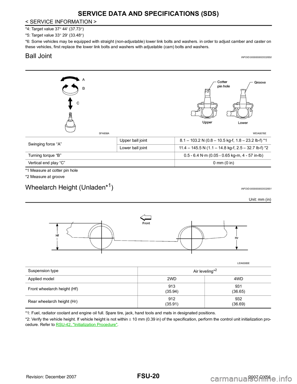
Ball JointINFOID:0000000003532650
*1 Measure at cotter pin hole
*2 Measure at groove
Wheelarch Height (Unladen*1)INFOID:0000000003532651
Unit: mm (in)
*1: Fuel, radiator coolant and engine oil full. Spare tire, jack, hand tools and mats in designated positions.
*2: Verify the vehicle height. If vehicle height is not within ± 10 mm (0.39 in) of the specification, perform the control unit initialization pro-
cedure. Refer to RSU-42, "
Initialization Procedure". Swinging force “A”Upper ball joint 8.1 – 103.2 N (0.8 – 10.5 kg-f, 1.8 – 23.2 lb-f) *1
Lower ball joint 11.4 – 145.5 N (1.1 – 14.8 kg-f, 2.5 – 32.7 lb-f) *2
Turning torque “B” 0.5 - 6.4 N·m (0.05 - 0.65 kg-m, 4 - 57 in-lb)
Vertical end play “C”0 mm (0 in)
SFA858AWEIA0076E
Suspension type
Air leveling*2
Applied model 2WD 4WD
Front wheelarch height (Hf)913
(35.94)931
(36.65)
Rear wheelarch height (Hr)912
(35.91)932
(36.69)
LEIA0085E
Page 2009 of 3061
TOW TRUCK TOWING
GI-43
< SERVICE INFORMATION >
C
D
E
F
G
H
I
J
K
L
MB
GI
N
O
P
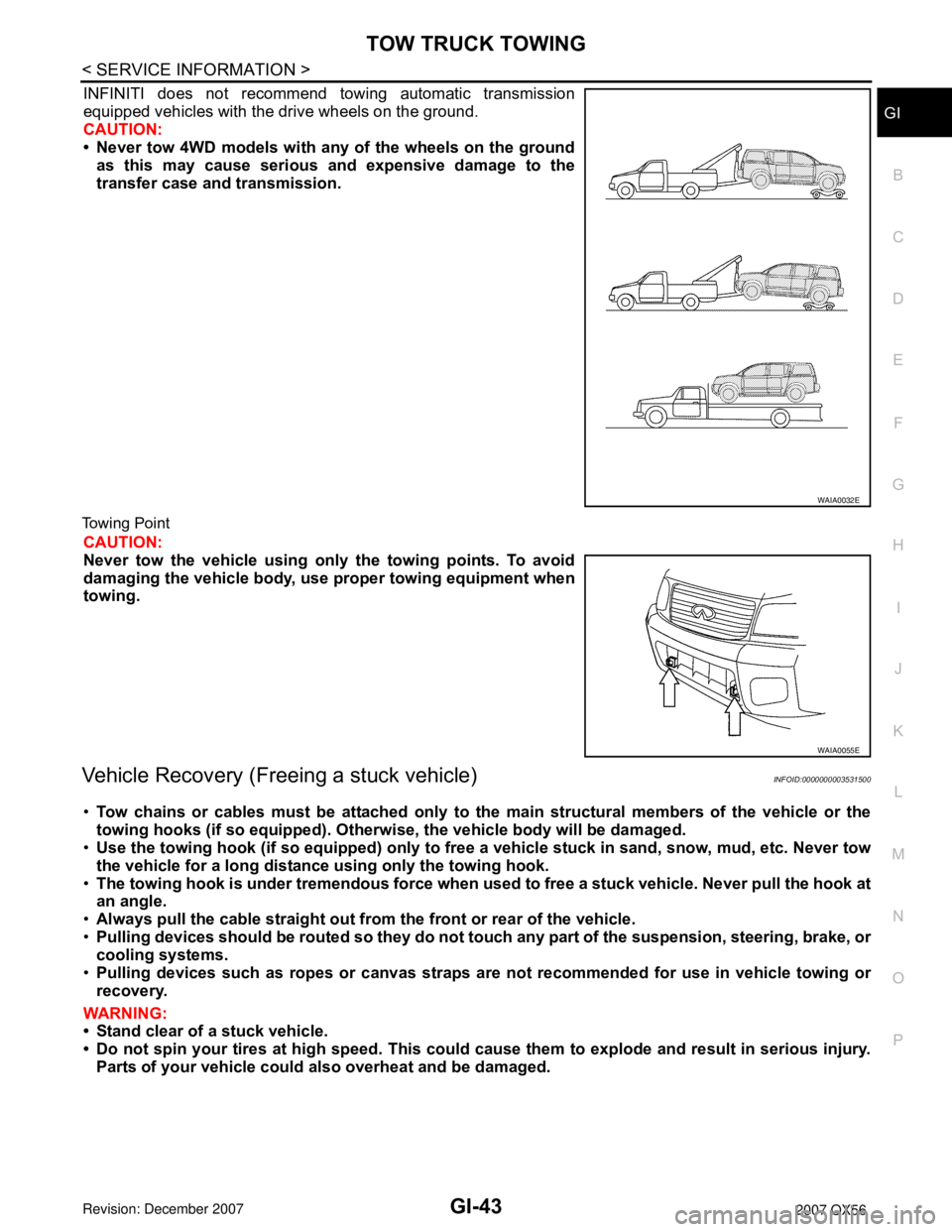
INFINITI does not recommend towing automatic transmission
equipped vehicles with the drive wheels on the ground.
CAUTION:
• Never tow 4WD models with any of the wheels on the ground
as this may cause serious and expensive damage to the
transfer case and transmission.
Towing Point
CAUTION:
Never tow the vehicle using only the towing points. To avoid
damaging the vehicle body, use proper towing equipment when
towing.
Vehicle Recovery (Freeing a stuck vehicle)INFOID:0000000003531500
•Tow chains or cables must be attached only to the main structural members of the vehicle or the
towing hooks (if so equipped). Otherwise, the vehicle body will be damaged.
•Use the towing hook (if so equipped) only to free a vehicle stuck in sand, snow, mud, etc. Never tow
the vehicle for a long distance using only the towing hook.
•The towing hook is under tremendous force when used to free a stuck vehicle. Never pull the hook at
an angle.
•Always pull the cable straight out from the front or rear of the vehicle.
•Pulling devices should be routed so they do not touch any part of the suspension, steering, brake, or
cooling systems.
•Pulling devices such as ropes or canvas straps are not recommended for use in vehicle towing or
recovery.
WARNING:
• Stand clear of a stuck vehicle.
• Do not spin your tires at high speed. This could cause them to explode and result in serious injury.
Parts of your vehicle could also overheat and be damaged.
WAIA0032E
WAIA0055E
Page 2111 of 3061
IDX-7
A
C
D
E
F
G
H
I
J
K
L B
IDX
ALPHABETICAL INDEX
Pressure switch 2 ............................................. AT-153
Pressure switch 3 ............................... AT-137, AT-157
Pressure switch 5 ............................... AT-145, AT-159
Pressure switch 6 ............................... AT-149, AT-161
Pressure test (A/T) ............................................. AT-52
Propeller shaft ........................................... PR-4, PR-8
Propeller shaft inspection .................................. MA-25
Propeller shaft on vehicle service ....................... PR-8
Propeller shaft vibration ............................ PR-4, PR-8
PS/SEN - Wiring diagram ................................ EC-471
R
R/VIEW - Wiring diagram .................................... DI-66
Radiator ............................................................. CO-14
Rear Audio Remote Control Unit ......................... AV-8
Rear axle ........................................................... RAX-5
Rear bumper ....................................................... EI-15
Rear case (Transfer) .......................... TF-148, TF-181
Rear combination lamp removal and installation ... LT-
101
Rear cover packing replacement diff. .............. RFD-28
Rear door ........................................... BL-117, GW-65
Rear seat belt ...................................................... SB-7
Rear suspension ............................................. RSU-23
Rear view monitor ............................................... DI-63
Rear washer .................................................... WW-29
Rear window defogger ..................................... GW-71
Rear wiper ....................................................... WW-29
Refrigerant connection precaution .................... ATC-6
Refrigerant discharging evacuating charging ATC-175
Refrigerant general precaution .......................... ATC-6
Refrigerant lines ........... ATC-175, ATC-183, ATC-184
Refrigerant pressure sensor ............ EC-692, ATC-184
Relay box .......................................................... PG-78
Remote keyless entry system ............................ BL-40
Removal and installation (A/T) ........... AT-238, AT-241
Removal and installation (Transfer) ................. TF-145
Ring gear diff. inspection ................................. RFD-18
Road wheel size ................................................. GI-51
Rocker cover ..................................................... EM-35
Room lamp ....................................................... LT-110
Room lamp - See Interior lamp ........................ LT-110
ROOM/L - Wiring diagram ................................ LT-116
RP/SEN - Wiring diagram ............................... EC-693
S
SAE J1979 - Service $01 - 09 ........................... EC-49
SEAT - Wiring diagram ..................................... SE-81
Seat belt inspection ............................... SB-12, MA-32
Seat belt pre-tensioner .................................... SRS-50
Seat belt, front ..................................................... SB-3
Seat belt, rear ...................................................... SB-7
Seat, front .......................................................... SE-89
Self-diagnosis (Transfer) .................................... TF-49
SEN/PW - Wiring diagram ............................... EC-483
SHIFT - Wiring diagram ................................... AT-217
Shift control (Transfer) ....................... TF-149, TF-176
Shift lock system .............................................. AT-216
Shock absorber (front) ..................................... FSU-11
Shock absorber (rear) ..................................... RSU-32
Side air bag (satellite) sensor .......................... SRS-49
Side curtain air bag .......................................... SRS-46
Side trim .............................................................. EI-35
SMJ (super multiple junction) ............................ PG-74
SONAR - Wiring diagram ................................... DI-53
Spare tire size ..................................................... GI-51
Spark plug ......................................................... EM-29
Specification value ........................................... EC-139
Speedometer ........................................................ DI-5
Spiral cable ...................................................... SRS-41
SROOF - Wiring diagram .................................. RF-13
SRS - See Supplemental Restraint System ...... SRS-5
SRS - Wiring diagram ...................................... SRS-13
SRS Trouble diagnoses ..................................... SRS-9
Stabilizer bar (front) ......................................... FSU-12
Stabilizer bar (rear) ......................................... RSU-39
Stall test (A/T) .................................................... AT-51
Standardized relay ............................................. PG-72
START - Wiring diagram ................................... SC-11
Starting system .................................................. SC-10
Steering gear, linkage and transfer gear inspection .....
MA-29
Steering linkage ................................................. PS-15
Steering wheel and column ................................. PS-7
Step lamp ......................................................... LT-111
Stop lamp ........................................................... LT-84
Stop lamp switch ................. EC-572, EC-584, EC-647
STOP/L - Wiring diagram ................................... LT-85
Strut (front) ...................................................... FSU-10
STSIG - Wiring diagram .................................... AT-97
Sub-oil pump (Transfer) ...................... TF-154, TF-167
Sun gear (Transfer) ............................ TF-149, TF-176
Sun roof, electric ................................................ RF-10
Sunload sensor .............................................. ATC-144
Sunroof .............................................................. RF-22
Supplemental Restraint System ........................ SRS-5
Supplemental restraint system - Wiring diagram . SRS-
13
Symbols and abbreviations ..................... GI-10, GI-23
Symptom matrix chart ........................................ EC-94
System readiness test (SRT) code .................... EC-55
T
Tachometer .......................................................... DI-5
Tail lamp ............................................................. LT-89
TAIL/L - Wiring diagram ...................................... LT-91
TCM circuit diagram .......................................... AT-50
TCS - Wiring diagram ..................................... BRC-16
TCS (traction control system) ........................... BRC-7
TCS component parts and connector location BRC-14
TCS wheel sensors ........................................ BRC-14
Telephone .......................................................... AV-62
Theft warning system - See Vehicle security (Theft warn-
ing) system ......................................................... BL-67
Thermometer ...................................................... DI-23
Page 2363 of 3061
MA-1
MAINTENANCE
C
D
E
F
G
H
I
J
K
M
SECTION MA
A
B
MA
N
O
P
CONTENTS
MAINTENANCE
SERVICE INFORMATION ............................2
PRECAUTIONS ...................................................2
Precaution for Supplemental Restraint System
(SRS) "AIR BAG" and "SEAT BELT PRE-TEN-
SIONER" ...................................................................
2
PREPARATION ...................................................3
Special Service Tool .................................................3
Commercial Service Tool ..........................................3
GENERAL MAINTENANCE ................................4
General Maintenance ................................................4
PERIODIC MAINTENANCE ................................6
Introduction of Periodic Maintenance ........................6
Maintenance for Off-road Driving (4WD only) ...........6
Schedule 1 ................................................................6
Schedule 2 ................................................................8
RECOMMENDED FLUIDS AND LUBRI-
CANTS ................................................................
10
Fluids and Lubricants ..............................................10
SAE Viscosity Number ............................................10
ENGINE MAINTENANCE ...................................12
Checking Drive Belts ...............................................12
Changing Engine Coolant .......................................12
Checking Fuel Line .................................................15
Changing Fuel Filter ................................................15
Changing Engine Air Cleaner Filter .........................15
Changing Engine Oil ................................................16
Changing Oil Filter ...................................................16
Changing Spark Plugs .............................................18
Checking EVAP Vapor Line .....................................19
CHASSIS AND BODY MAINTENANCE ...........20
Changing In-cabin Microfilter ...................................20
Checking Exhaust System .......................................21
Checking Automatic Transmission Fluid (ATF) .......21
Changing Automatic Transmission Fluid (ATF) .......23
Changing Transfer Fluid ..........................................23
Checking Transfer Fluid ..........................................24
Checking Propeller Shaft .........................................24
Checking Final Drive Oil ..........................................24
Changing Final Drive Oil ..........................................25
Balancing Wheels ....................................................25
Tire Rotation ............................................................27
Checking Brake Fluid Level and Leaks ...................27
CheckingBrake Line and Cables .............................27
Checking Disc Brake ...............................................27
Checking Steering Gear and Linkage ......................28
Checking Power Steering Fluid and Line ................28
Checking Axle and Suspension Parts .....................29
Lubricating Locks, Hinges and Hood Latches .........30
Checking Seat Belts, Buckles, Retractors, An-
chors and Adjusters .................................................
30
Page 2369 of 3061
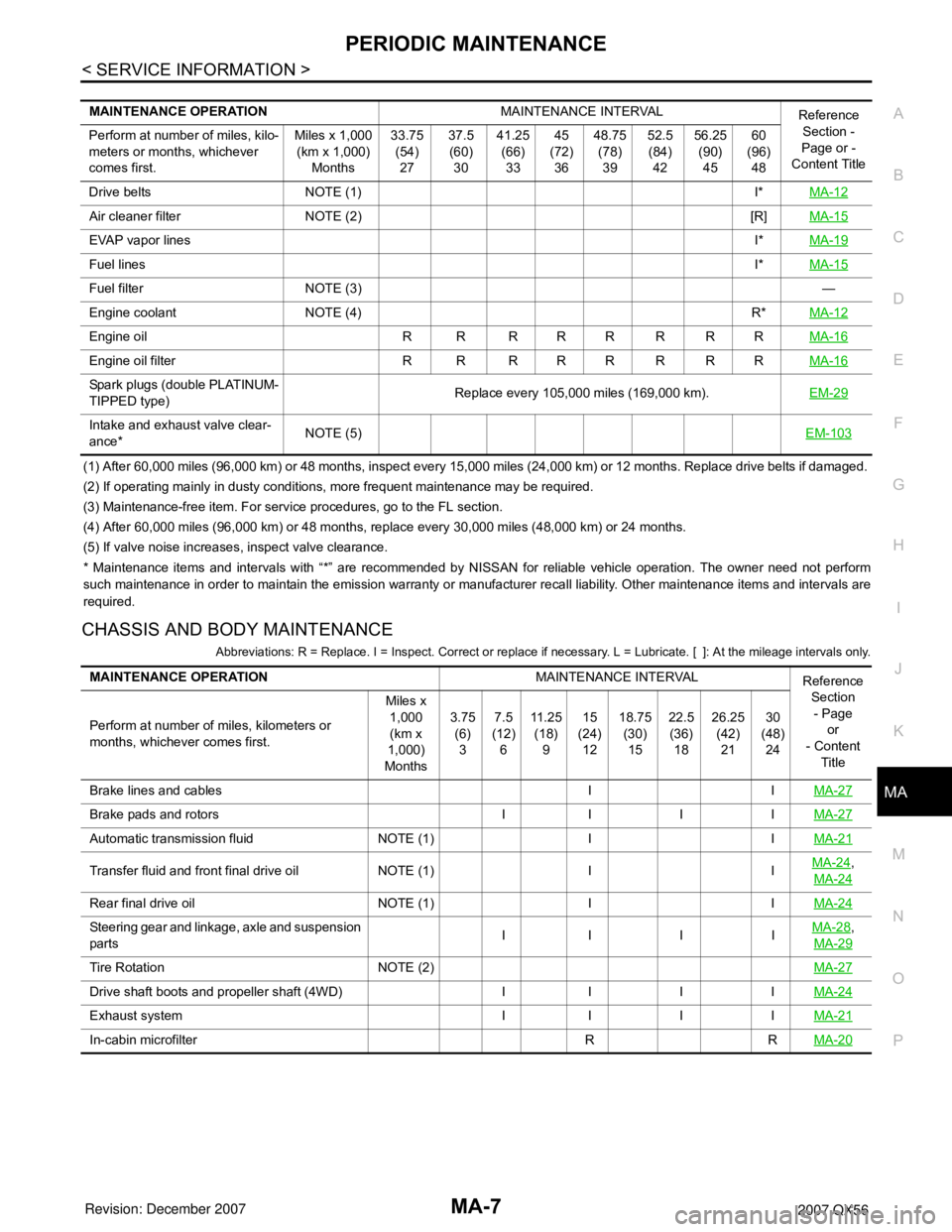
PERIODIC MAINTENANCE
MA-7
< SERVICE INFORMATION >
C
D
E
F
G
H
I
J
K
MA
B
MA
N
O
P
(1) After 60,000 miles (96,000 km) or 48 months, inspect every 15,000 miles (24,000 km) or 12 months. Replace drive belts if damaged.
(2) If operating mainly in dusty conditions, more frequent maintenance may be required.
(3) Maintenance-free item. For service procedures, go to the FL section.
(4) After 60,000 miles (96,000 km) or 48 months, replace every 30,000 miles (48,000 km) or 24 months.
(5) If valve noise increases, inspect valve clearance.
* Maintenance items and intervals with “*” are recommended by NISSAN for reliable vehicle operation. The owner need not perform
such maintenance in order to maintain the emission warranty or manufacturer recall liability. Other maintenance items and intervals are
required.
CHASSIS AND BODY MAINTENANCE
Abbreviations: R = Replace. I = Inspect. Correct or replace if necessary. L = Lubricate. [ ]: At the mileage intervals only.
MAINTENANCE OPERATIONMAINTENANCE INTERVAL
Reference
Section -
Page or -
Content Title Perform at number of miles, kilo-
meters or months, whichever
comes first.Miles x 1,000
(km x 1,000)
Months33.75
(54)
2737.5
(60)
3041.25
(66)
3345
(72)
3648.75
(78)
3952.5
(84)
4256.25
(90)
4560
(96)
48
Drive belts NOTE (1) I*MA-12
Air cleaner filter NOTE (2) [R]MA-15
EVAP vapor linesI*MA-19
Fuel linesI*MA-15
Fuel filter NOTE (3)—
Engine coolant NOTE (4) R*MA-12
Engine oil R R R R R R R RMA-16
Engine oil filter R R R R R R R RMA-16
Spark plugs (double PLATINUM-
TIPPED type)Replace every 105,000 miles (169,000 km).EM-29
Intake and exhaust valve clear-
ance*NOTE (5)EM-103
MAINTENANCE OPERATIONMAINTENANCE INTERVAL
Reference
Section
- Page
or
- Content
Title Perform at number of miles, kilometers or
months, whichever comes first.Miles x
1,000
(km x
1,000)
Months3.75
(6)
37.5
(12)
611 . 2 5
(18)
915
(24)
1218.75
(30)
1522.5
(36)
1826.25
(42)
2130
(48)
24
Brake lines and cables I IMA-27
Brake pads and rotors I I I IMA-27
Automatic transmission fluid NOTE (1) I IMA-21
Transfer fluid and front final drive oil NOTE (1) I IMA-24,
MA-24
Rear final drive oil NOTE (1) I IMA-24
Steering gear and linkage, axle and suspension
partsII I IMA-28,
MA-29
Tire Rotation NOTE (2)MA-27
Drive shaft boots and propeller shaft (4WD) I I I IMA-24
Exhaust system I I I IMA-21
In-cabin microfilter R RMA-20
Page 2391 of 3061
CHASSIS AND BODY MAINTENANCE
MA-29
< SERVICE INFORMATION >
C
D
E
F
G
H
I
J
K
MA
B
MA
N
O
P
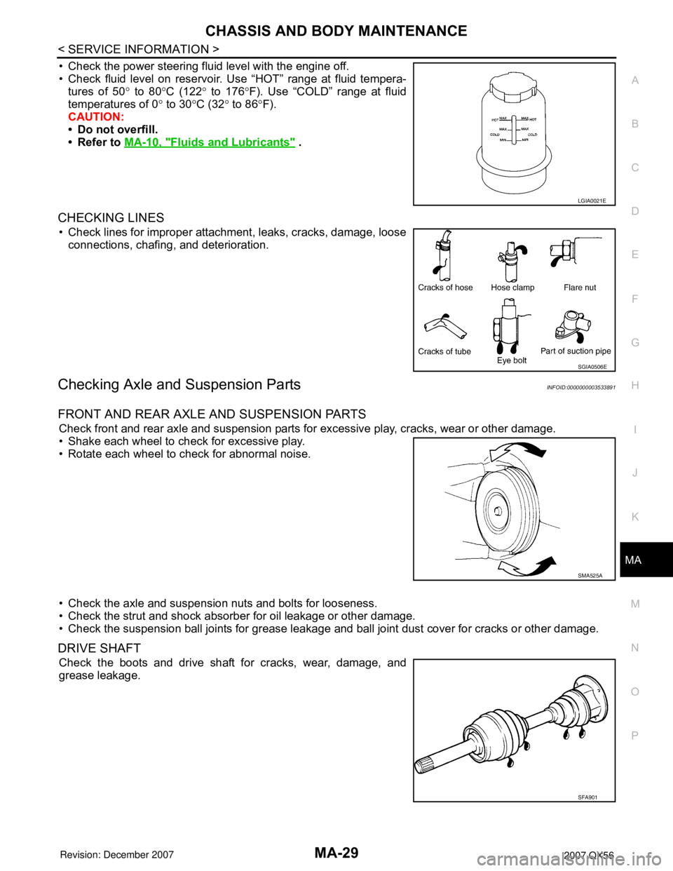
• Check the power steering fluid level with the engine off.
• Check fluid level on reservoir. Use “HOT” range at fluid tempera-
tures of 50° to 80°C (122° to 176°F). Use “COLD” range at fluid
temperatures of 0° to 30°C (32° to 86°F).
CAUTION:
• Do not overfill.
• Refer to MA-10, "
Fluids and Lubricants" .
CHECKING LINES
• Check lines for improper attachment, leaks, cracks, damage, loose
connections, chafing, and deterioration.
Checking Axle and Suspension PartsINFOID:0000000003533891
FRONT AND REAR AXLE AND SUSPENSION PARTS
Check front and rear axle and suspension parts for excessive play, cracks, wear or other damage.
• Shake each wheel to check for excessive play.
• Rotate each wheel to check for abnormal noise.
• Check the axle and suspension nuts and bolts for looseness.
• Check the strut and shock absorber for oil leakage or other damage.
• Check the suspension ball joints for grease leakage and ball joint dust cover for cracks or other damage.
DRIVE SHAFT
Check the boots and drive shaft for cracks, wear, damage, and
grease leakage.
LGIA0021E
SGIA0506E
SMA525A
SFA901
Page 2462 of 3061

PG-60
< SERVICE INFORMATION >
HARNESS
Code Section Wiring Diagram Name
A/C,A ATC Auto Air Conditioner
A/SUSP RSU Rear Air Suspension
AF1B1 EC Air Fuel Ratio (A/F) Sensor 1 (Bank 1)
AF1B2 EC Air Fuel Ratio (A/F) Sensor 1 (Bank 2)
AF1HB1 EC Air Fuel Ratio (A/F) Sensor 1 (Bank 1)
AF1HB2 EC Air Fuel Ratio (A/F) Sensor 1 (Bank 2)
APPS1 EC Accelerator Pedal Position Sensor
APPS2 EC Accelerator Pedal Position Sensor
APPS3 EC Accelerator Pedal Position Sensor
ASC/BS EC ASCD Brake Switch
ASC/SW EC ASCD Steering Switch
ASCBOF EC ASCD Brake Switch
ASCIND EC ASCD Indicator
A/T AT A/T Assembly
AT/IND DI A/T Indicator Lamp
AUDIO AV Audio
AUT/DP SE Automatic Drive Positioner
AUTO/L LT Auto Light Control
B/CLOS BL Back Door Auto Closure System
BACK/L LT Back-up Lamp
BRK/SW EC Brake Switch
CAN EC CAN Communication Line
CAN LAN CAN System
CHARGE SC Charging System
CHIME DI Warning Chime
CLOCK DI Clock
COOL/F EC Cooling Fan Control
COMBSW LT Combination Switch
COMM AV Audio Visual Communication System
COMPAS DI Compass and Thermometer
D/LOCK BL Power Door Lock
DEF GW Rear Window Defogger
DTRL LT Headlamp - With Daytime Light System
DVD AV DVD Entertainment System
ECM/PW EC ECM Power Supply for Back-Up
ECTS EC Engine Coolant Temperature Sensor
ETC1 EC Electric Throttle Control Function
ETC2 EC Throttle Control Motor Relay
ETC3 EC Throttle Control Motor
F/FOG LT Front Fog Lamp
F/PUMP EC Fuel Pump
FTTS EC Fuel Tank Temperature Sensor
FUELB1 EC Fuel Injection System Bank 1
FUELB2 EC Fuel Injection System Bank 2
H/AIM LT Headlamp Aiming Control
H/PHON AV Hands Free Telephone
H/LAMP LT Headlamp
HORN WW Horn
HSEAT SE Heated Seat
ICC ACS Intelligent Cruise Control
ICCBOF EC ICC Brake Switch
Page 2480 of 3061

NOISE, VIBRATION AND HARSHNESS (NVH) TROUBLESHOOTINGPR-3
< SERVICE INFORMATION >
CEF
G H
I
J
K L
M A
B
PR
N
O P
NOISE, VIBRATION AND HARSHN ESS (NVH) TROUBLESHOOTING
NVH Troubleshooting ChartINFOID:0000000003532575
Use the chart below to help you find t he cause of the symptom. If necessary, repair or replace these parts.
×: ApplicableReference page
PR-4
(front)
PR-8 (rear)
PR-4 (front)
PR-8 (rear)
PR-4 (front)
PR-8 (rear)
FFD-6, "
NVH Troubleshooting Chart
"
RFD-7, "
NVH Troubleshooting Chart
"
FAX-4, "
NVH Troubleshooting Chart
"
RAX-4, "
NVH Troubleshooting Chart
"
FSU-4, "
NVH Troubleshooting Chart
"
RSU-4, "
NVH Troubleshooting Chart
"
WT-4, "
NVH Troubleshooting Chart
"
WT-4, "
NVH Troubleshooting Chart
"
FAX-4, "
NVH Troubleshooting Chart
"
BR-4, "
NVH Troubleshooting Chart
"
PS-5, "
NVH Troubleshooting Chart
"
Possible cause and suspected parts
Uneven rotation torque
Rotation imbalance
Excessive run out
Differential
Axle
Suspension
Tires
Road wheel
Drive shaft
Brakes
Ste eri ng
Symptom Noise
×××××××××××
Shake ×××××××
Vibration ××××××××