Page 1905 of 3061
FFD-6
< SERVICE INFORMATION >
NOISE, VIBRATION AND HARSHNESS (NVH) TROUBLESHOOTING
NOISE, VIBRATION AND HARSHNESS (NVH) TROUBLESHOOTING
NVH Troubleshooting ChartINFOID:0000000003532587
Use the chart below to help you find the cause of the symptom. If necessary, repair or replace these parts.
×: ApplicableReference page
FFD-13FFD-13FFD-13FFD-13FFD-13FFD-7
PR-3, "
NVH Troubleshooting Chart
"
FAX-4, "
NVH Troubleshooting Chart
"
FSU-4, "
NVH Troubleshooting Chart
"
WT-4, "
NVH Troubleshooting Chart
"
WT-4, "
NVH Troubleshooting Chart
"
FAX-4, "
NVH Troubleshooting Chart
"
BR-4, "
NVH Troubleshooting Chart
"
PS-5, "
NVH Troubleshooting Chart
"
Possible cause and SUSPECTED PARTS
Gear tooth rough
Gear contact improper
Tooth surfaces worn
Incorrect backlash
Companion flange excessive runout
Gear oil improper
PROPELLER SHAFT
FRONT AXLE
FRONT SUSPENSION
TIRES
ROAD WHEEL
DRIVE SHAFT
BRAKES
STEERING
Symptom Noise××××××××××××××
Page 1947 of 3061

FSU-1
SUSPENSION
C
D
F
G
H
I
J
K
L
M
SECTION FSU
A
B
FSU
N
O
PCONTENTS
FRONT SUSPENSION
SERVICE INFORMATION ............................2
PRECAUTIONS ...................................................2
Precaution .................................................................2
PREPARATION ...................................................3
Special Service Tool .................................................3
Commercial Service Tool ..........................................3
NOISE, VIBRATION AND HARSHNESS
(NVH) TROUBLESHOOTING .............................
4
NVH Troubleshooting Chart ......................................4
FRONT SUSPENSION ASSEMBLY ...................5
Component ................................................................5
ON-VEHICLE SERVICE ......................................6
Front Suspension Parts .............................................6
Front Wheel Alignment ..............................................6
COIL SPRING AND SHOCK ABSORBER ........10
Removal and Installation .........................................10
Disassembly and Assembly ....................................10
STABILIZER BAR ..............................................12
Removal and Installation .........................................12
UPPER LINK .....................................................13
Removal and Installation .........................................13
LOWER LINK ....................................................14
Removal and Installation .........................................14
UPPER BALL JOINT AND LOWER BALL
JOINT ................................................................
15
Removal and Installation .........................................15
Inspection ................................................................15
KNUCKLE .........................................................17
On-Vehicle Inspection and Service .........................17
Removal and Installation .........................................17
SERVICE DATA AND SPECIFICATIONS
(SDS) .................................................................
19
General Specification ..............................................19
Spring Free Height ..................................................19
Wheel Alignment (Unladen*1) *6 .............................19
Ball Joint ..................................................................20
Wheelarch Height (Unladen*1) ................................20
Page 1948 of 3061
FSU-2
< SERVICE INFORMATION >
PRECAUTIONS
SERVICE INFORMATION
PRECAUTIONS
PrecautionINFOID:0000000003532631
• When installing the rubber bushings, the final tightening must be done under unladen condition and with the
tires on level ground. Oil will shorten the life of the rubber bushings, so wipe off any spilled oil immediately.
• Unladen condition means the fuel tank, engine coolant and lubricants are at the full specification. The spare
tire, jack, hand tools, and mats are in their designated positions.
• After installing suspension components, check the wheel alignment.
• Lock nuts are not reusable. Always use new lock nuts for installation. New lock nuts are pre-oiled, do not
apply any additional lubrication.
Page 1950 of 3061

FSU-4
< SERVICE INFORMATION >
NOISE, VIBRATION AND HARSHNESS (NVH) TROUBLESHOOTING
NOISE, VIBRATION AND HARSHNESS (NVH) TROUBLESHOOTING
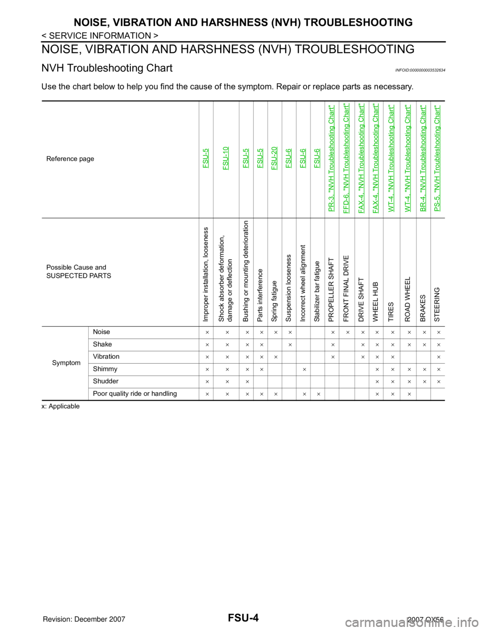
NVH Troubleshooting ChartINFOID:0000000003532634
Use the chart below to help you find the cause of the symptom. Repair or replace parts as necessary.
x: ApplicableReference page
FSU-5FSU-10FSU-5FSU-5FSU-20FSU-6FSU-6FSU-6
PR-3, "
NVH Troubleshooting Chart
"
FFD-6, "
NVH Troubleshooting Chart
"
FAX-4, "
NVH Troubleshooting Chart
"
FAX-4, "
NVH Troubleshooting Chart
"
WT-4, "
NVH Troubleshooting Chart
"
WT-4, "
NVH Troubleshooting Chart
"
BR-4, "
NVH Troubleshooting Chart
"
PS-5, "
NVH Troubleshooting Chart
"
Possible Cause and
SUSPECTED PARTS
Improper installation, looseness
Shock absorber deformation,
damage or deflection
Bushing or mounting deterioration
Parts interference
Spring fatigue
Suspension looseness
Incorrect wheel alignment
Stabilizer bar fatigue
PROPELLER SHAFT
FRONT FINAL DRIVE
DRIVE SHAFT
WHEEL HUB
TIRES
ROAD WHEEL
BRAKES
STEERING
SymptomNoise× × ×××× × × ×× × × ××
Shake× × ×× × × ×× × × ××
Vibration× × ××× × ×× × ×
Shimmy× × ×× × × × × ××
Shudder××× ×××××
Poor quality ride or handling××××× ×× ×××
Page 1951 of 3061
FRONT SUSPENSION ASSEMBLY
FSU-5
< SERVICE INFORMATION >
C
D
F
G
H
I
J
K
L
MA
B
FSU
N
O
P
FRONT SUSPENSION ASSEMBLY
ComponentINFOID:0000000003532635
1. Dust cover 2. Shock absorber 3. Upper link
4. Steering knuckle 5. Cotter pin 6. Bolt
7. Jounce bumper 8. Washer 9. Lower link
10. Stabilizer bar 11. Stabilizer bar bushing 12. Stabilizer bar mounting bracket
13. Connecting rod 14. Coil spring 15. Upper seat
16. Upper spring seat 17. Shock absorber bushing 18. Shock absorber mounting insulator
19. Spacer 20. Washer⇐Front
WEIA0156E
Page 1952 of 3061

FSU-6
< SERVICE INFORMATION >
ON-VEHICLE SERVICE
ON-VEHICLE SERVICE
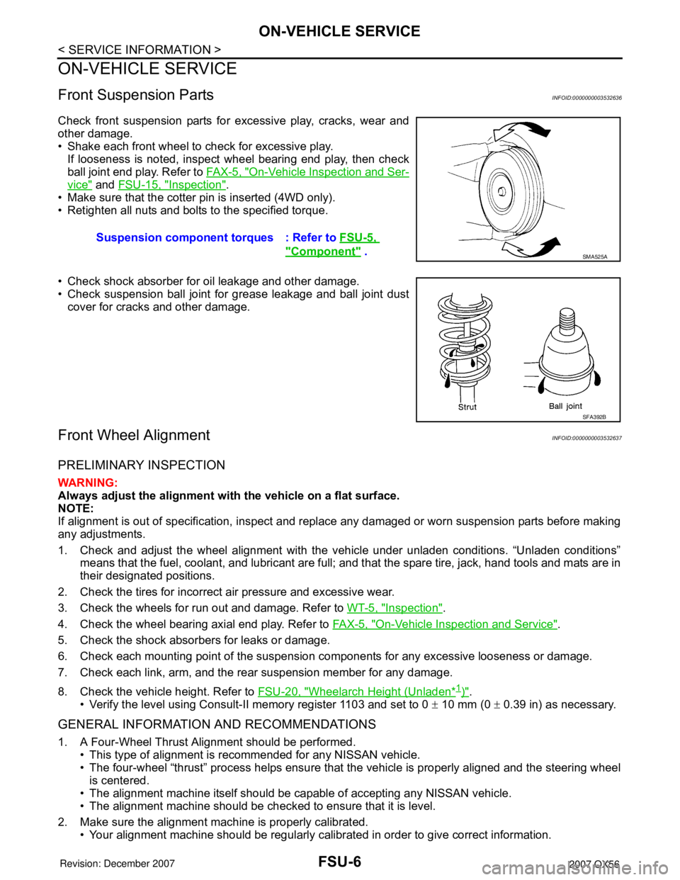
Front Suspension PartsINFOID:0000000003532636
Check front suspension parts for excessive play, cracks, wear and
other damage.
• Shake each front wheel to check for excessive play.
If looseness is noted, inspect wheel bearing end play, then check
ball joint end play. Refer to FA X - 5 , "
On-Vehicle Inspection and Ser-
vice" and FSU-15, "Inspection".
• Make sure that the cotter pin is inserted (4WD only).
• Retighten all nuts and bolts to the specified torque.
• Check shock absorber for oil leakage and other damage.
• Check suspension ball joint for grease leakage and ball joint dust
cover for cracks and other damage.
Front Wheel AlignmentINFOID:0000000003532637
PRELIMINARY INSPECTION
WARNING:
Always adjust the alignment with the vehicle on a flat surface.
NOTE:
If alignment is out of specification, inspect and replace any damaged or worn suspension parts before making
any adjustments.
1. Check and adjust the wheel alignment with the vehicle under unladen conditions. “Unladen conditions”
means that the fuel, coolant, and lubricant are full; and that the spare tire, jack, hand tools and mats are in
their designated positions.
2. Check the tires for incorrect air pressure and excessive wear.
3. Check the wheels for run out and damage. Refer to WT-5, "
Inspection".
4. Check the wheel bearing axial end play. Refer to FA X - 5 , "
On-Vehicle Inspection and Service".
5. Check the shock absorbers for leaks or damage.
6. Check each mounting point of the suspension components for any excessive looseness or damage.
7. Check each link, arm, and the rear suspension member for any damage.
8. Check the vehicle height. Refer to FSU-20, "
Wheelarch Height (Unladen*1)".
• Verify the level using Consult-II memory register 1103 and set to 0 ± 10 mm (0 ± 0.39 in) as necessary.
GENERAL INFORMATION AND RECOMMENDATIONS
1. A Four-Wheel Thrust Alignment should be performed.
• This type of alignment is recommended for any NISSAN vehicle.
• The four-wheel “thrust” process helps ensure that the vehicle is properly aligned and the steering wheel
is centered.
• The alignment machine itself should be capable of accepting any NISSAN vehicle.
• The alignment machine should be checked to ensure that it is level.
2. Make sure the alignment machine is properly calibrated.
• Your alignment machine should be regularly calibrated in order to give correct information.Suspension component torques : Refer to FSU-5,
"Component" . SMA525A
SFA392B
Page 1955 of 3061
ON-VEHICLE SERVICE
FSU-9
< SERVICE INFORMATION >
C
D
F
G
H
I
J
K
L
MA
B
FSU
N
O
P
- Steering column
- Front suspension components
If found that they are worn or damaged, replace them with new ones.
Page 1965 of 3061

SERVICE DATA AND SPECIFICATIONS (SDS)
FSU-19
< SERVICE INFORMATION >
C
D
F
G
H
I
J
K
L
MA
B
FSU
N
O
P
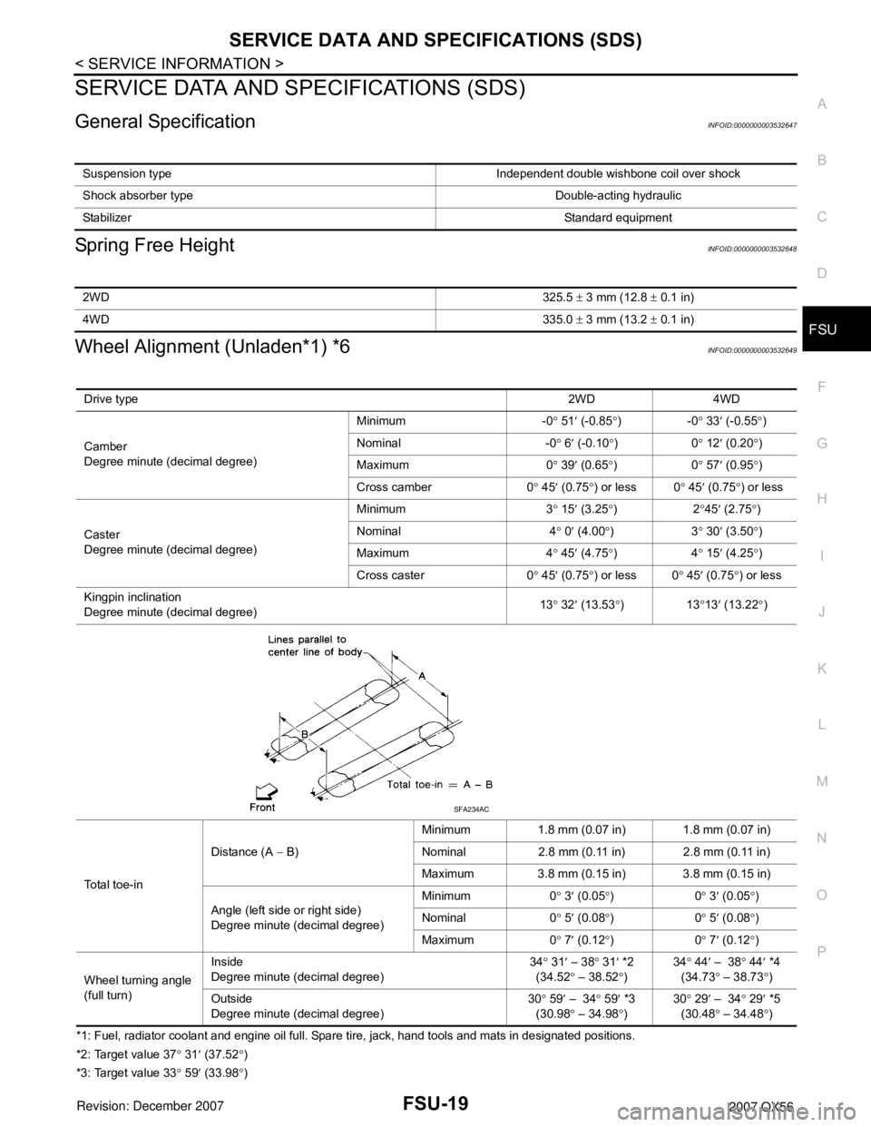
SERVICE DATA AND SPECIFICATIONS (SDS)
General SpecificationINFOID:0000000003532647
Spring Free HeightINFOID:0000000003532648
Wheel Alignment (Unladen*1) *6INFOID:0000000003532649
*1: Fuel, radiator coolant and engine oil full. Spare tire, jack, hand tools and mats in designated positions.
*2: Target value 37° 31′ (37.52°)
*3: Target value 33° 59′ (33.98°) Suspension type Independent double wishbone coil over shock
Shock absorber type Double-acting hydraulic
StabilizerStandard equipment
2WD325.5 ± 3 mm (12.8 ± 0.1 in)
4WD335.0 ± 3 mm (13.2 ± 0.1 in)
Drive type2WD 4WD
Camber
Degree minute (decimal degree)Minimum -0° 51′ (-0.85°)-0° 33′ (-0.55°)
Nominal -0° 6′ (-0.10°)0° 12′ (0.20°)
Maximum 0° 39′ (0.65°)0° 57′ (0.95°)
Cross camber 0° 45′ (0.75°) or less 0° 45′ (0.75°) or less
Caster
Degree minute (decimal degree)Minimum 3° 15′ (3.25°)2°45′ (2.75°)
Nominal 4° 0′ (4.00°)3° 30′ (3.50°)
Maximum 4° 45′ (4.75°)4° 15′ (4.25°)
Cross caster 0° 45′
(0.75°) or less 0° 45′ (0.75°) or less
Kingpin inclination
Degree minute (decimal degree)13° 32′ (13.53°)13°13′ (13.22°)
Total toe-inDistance (A − B)Minimum 1.8 mm (0.07 in) 1.8 mm (0.07 in)
Nominal 2.8 mm (0.11 in) 2.8 mm (0.11 in)
Maximum 3.8 mm (0.15 in) 3.8 mm (0.15 in)
Angle (left side or right side)
Degree minute (decimal degree)Minimum 0° 3′ (0.05°)0° 3′ (0.05°)
Nominal 0° 5′ (0.08°)0° 5′ (0.08°)
Maximum 0° 7′ (0.12°)0° 7′ (0.12°)
Wheel turning angle
(full turn)Inside
Degree minute (decimal degree)34° 31′ – 38° 31′ *2
(34.52° – 38.52°)34° 44′ – 38° 44′ *4
(34.73° – 38.73
°)
Outside
Degree minute (decimal degree)30° 59′ – 34° 59′ *3
(30.98° – 34.98°)30° 29′ – 34° 29′ *5
(30.48° – 34.48°)
SFA234AC