2007 INFINITI QX56 fuses
[x] Cancel search: fusesPage 2096 of 3061
REAR WINDOW DEFOGGER
GW-77
< SERVICE INFORMATION >
C
D
E
F
G
H
J
K
L
MA
B
GW
N
O
P
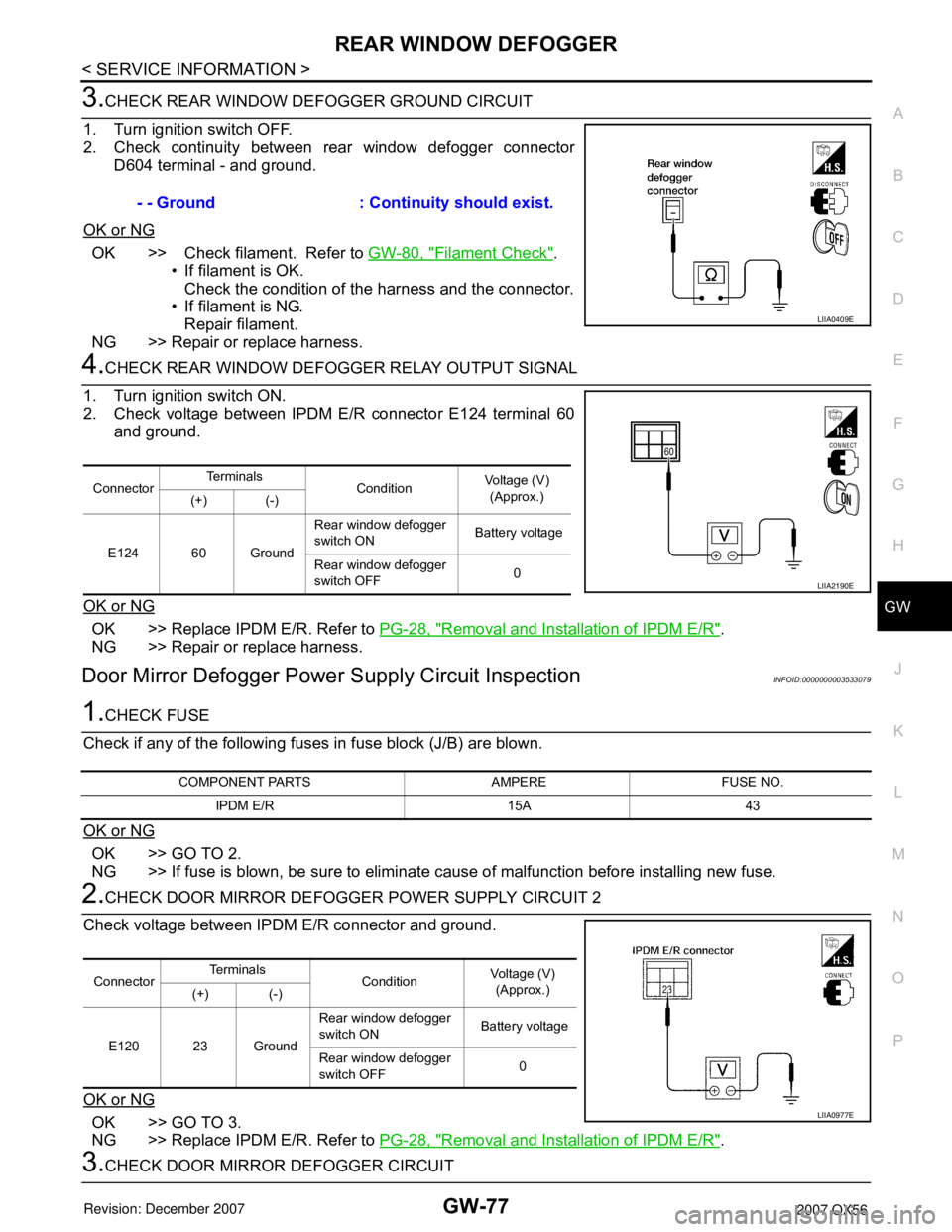
3.CHECK REAR WINDOW DEFOGGER GROUND CIRCUIT
1. Turn ignition switch OFF.
2. Check continuity between rear window defogger connector
D604 terminal - and ground.
OK or NG
OK >> Check filament. Refer to GW-80, "Filament Check".
• If filament is OK.
Check the condition of the harness and the connector.
• If filament is NG.
Repair filament.
NG >> Repair or replace harness.
4.CHECK REAR WINDOW DEFOGGER RELAY OUTPUT SIGNAL
1. Turn ignition switch ON.
2. Check voltage between IPDM E/R connector E124 terminal 60
and ground.
OK or NG
OK >> Replace IPDM E/R. Refer to PG-28, "Removal and Installation of IPDM E/R".
NG >> Repair or replace harness.
Door Mirror Defogger Power Supply Circuit InspectionINFOID:0000000003533079
1.CHECK FUSE
Check if any of the following fuses in fuse block (J/B) are blown.
OK or NG
OK >> GO TO 2.
NG >> If fuse is blown, be sure to eliminate cause of malfunction before installing new fuse.
2.CHECK DOOR MIRROR DEFOGGER POWER SUPPLY CIRCUIT 2
Check voltage between IPDM E/R connector and ground.
OK or NG
OK >> GO TO 3.
NG >> Replace IPDM E/R. Refer to PG-28, "
Removal and Installation of IPDM E/R".
3.CHECK DOOR MIRROR DEFOGGER CIRCUIT- - Ground : Continuity should exist.
LIIA0409E
ConnectorTe r m i n a l s
ConditionVoltage (V)
(Approx.)
(+) (-)
E124 60 GroundRear window defogger
switch ON Battery voltage
Rear window defogger
switch OFF0
LIIA2190E
COMPONENT PARTS AMPERE FUSE NO.
IPDM E/R 15A 43
ConnectorTe r m i n a l s
ConditionVoltage (V)
(Approx.)
(+) (-)
E120 23 GroundRear window defogger
switch ON Battery voltage
Rear window defogger
switch OFF0
LIIA0977E
Page 2428 of 3061
PG-26
< SERVICE INFORMATION >
IPDM E/R (INTELLIGENT POWER DISTRIBUTION MODULE ENGINE ROOM)
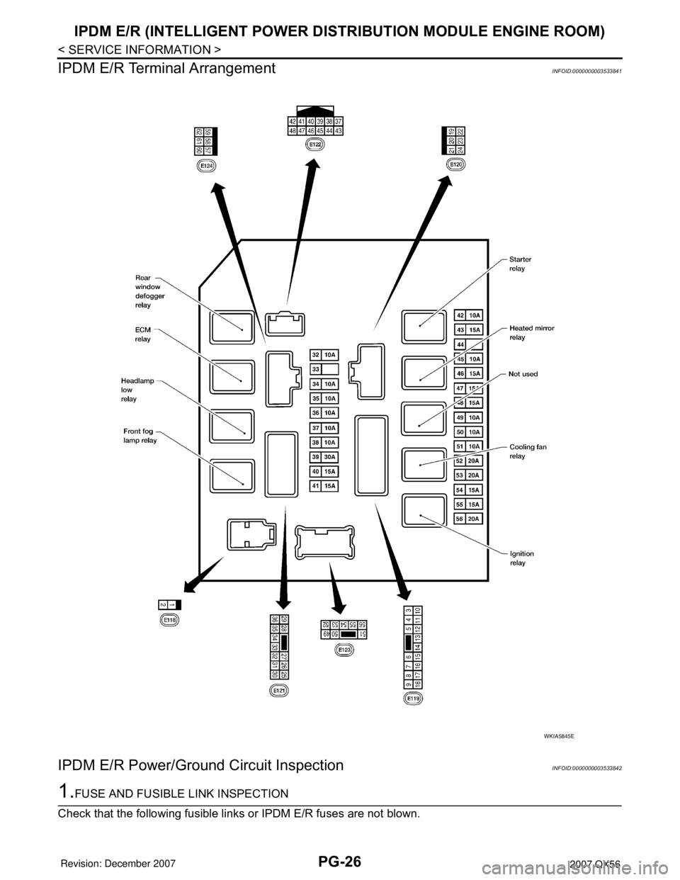
IPDM E/R Terminal Arrangement
INFOID:0000000003533841
IPDM E/R Power/Ground Circuit InspectionINFOID:0000000003533842
1.FUSE AND FUSIBLE LINK INSPECTION
Check that the following fusible links or IPDM E/R fuses are not blown.
WKIA5845E
Page 2609 of 3061
TROUBLE DIAGNOSES FOR SYMPTOMS
RSU-19
< SERVICE INFORMATION >
C
D
F
G
H
I
J
K
L
MA
B
RSU
N
O
P
TROUBLE DIAGNOSES FOR SYMPTOMS
Load Leveling Rear Air Suspension System Does Not OperateINFOID:0000000003532667
1.CHECK WARNING LAMP ACTIVATION
Make sure warning lamp remains off while driving.
OK or NG
OK >> GO TO 2.
NG >> Carry out self-diagnosis. Refer to RSU-11, "
CONSULT-II Function (AIR LEVELIZER)" .
2.CHECK FUSES AND FUSIBLE LINK
Check that the following fuses and fusible link are not blown.
OK or NG
OK >> GO TO 3.
NG >> If fuse or fusible link is blown, be sure to eliminate cause of malfunction before installing new fuse
or fusible link.
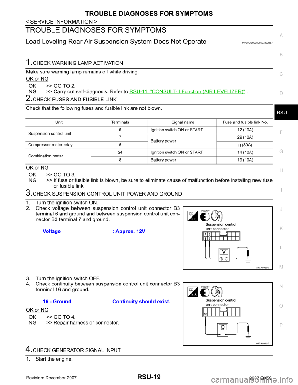
3.CHECK SUSPENSION CONTROL UNIT POWER AND GROUND
1. Turn the ignition switch ON.
2. Check voltage between suspension control unit connector B3
terminal 6 and ground and between suspension control unit con-
nector B3 terminal 7 and ground.
3. Turn the ignition switch OFF.
4. Check continuity between suspension control unit connector B3
terminal 16 and ground.
OK or NG
OK >> GO TO 4.
NG >> Repair harness or connector.
4.CHECK GENERATOR SIGNAL INPUT
1. Start the engine.
Unit Terminals Signal name Fuse and fusible link No.
Suspension control unit6 Ignition switch ON or START 12 (10A)
7
Battery power29 (10A)
Compressor motor relay 5 g (30A)
Combination meter24 Ignition switch ON or START 14 (10A)
8 Battery power 19 (10A)
Voltage : Approx. 12V
WEIA0069E
16 - Ground Continuity should exist.
WEIA0070E
Page 2669 of 3061
CHARGING SYSTEM
SC-21
< SERVICE INFORMATION >
C
D
E
F
G
H
I
J
L
MA
B
SC
N
O
P
NG >> Repair battery terminal connections.
2.CHECK FUSE AND FUSIBLE LINK
Check for blown fuses and fusible link.
OK or NG
OK >> GO TO 3.
NG >> If fuse is blown, be sure to eliminate cause of malfunction before installing new fuse.
3.CHECK GENERATOR DRIVE BELT TENSION
Check generator drive belt tension. Refer to EM-13, "
Checking Drive Belts".
OK or NG
OK >> Inspection End.
NG >> Repair as needed.
DIAGNOSTIC PROCEDURE 1
Check Charge Warning Lamp Circuit
1.CHECK CHARGE WARNING LAMP CIRCUIT CONNECTION
1. Turn the ignition switch OFF.
2. Check terminal 2 harness connector.
OK or NG
OK >> GO TO 2.
NG >> Repair terminal 2 connection. Confirm repair by performing complete Battery/Starting/Charging
system test. Refer to "Trouble Diagnoses with Battery/Starting/Charging System Tester" .
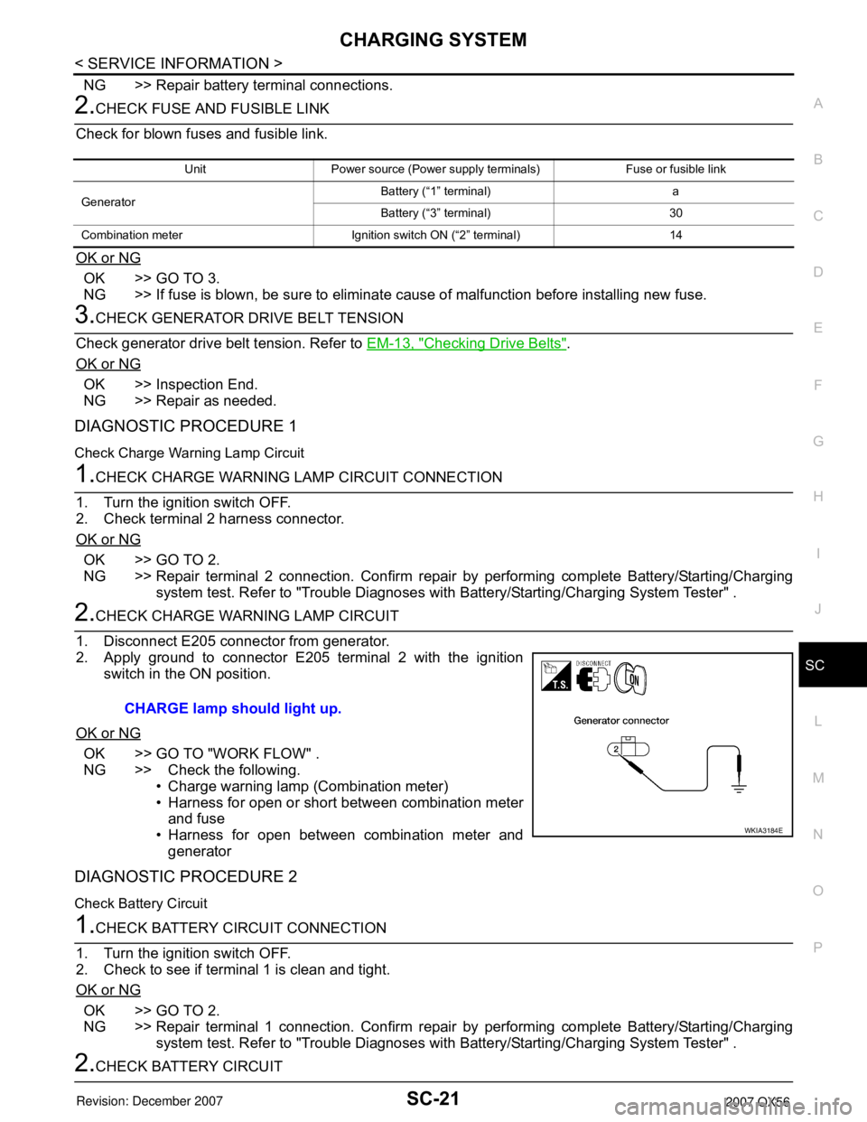
2.CHECK CHARGE WARNING LAMP CIRCUIT
1. Disconnect E205 connector from generator.
2. Apply ground to connector E205 terminal 2 with the ignition
switch in the ON position.
OK or NG
OK >> GO TO "WORK FLOW" .
NG >> Check the following.
• Charge warning lamp (Combination meter)
• Harness for open or short between combination meter
and fuse
• Harness for open between combination meter and
generator
DIAGNOSTIC PROCEDURE 2
Check Battery Circuit
1.CHECK BATTERY CIRCUIT CONNECTION
1. Turn the ignition switch OFF.
2. Check to see if terminal 1 is clean and tight.
OK or NG
OK >> GO TO 2.
NG >> Repair terminal 1 connection. Confirm repair by performing complete Battery/Starting/Charging
system test. Refer to "Trouble Diagnoses with Battery/Starting/Charging System Tester" .
2.CHECK BATTERY CIRCUIT
Unit Power source (Power supply terminals) Fuse or fusible link
GeneratorBattery (“1” terminal) a
Battery (“3” terminal) 30
Combination meter Ignition switch ON (“2” terminal) 14
CHARGE lamp should light up.
WKIA3184E
Page 2703 of 3061
AUTOMATIC DRIVE POSITIONER
SE-31
< SERVICE INFORMATION >
C
D
E
F
G
H
J
K
L
MA
B
SE
N
O
P
It is possible to set sliding front seat for entry/exit of vehicle by pressing set switch.
*: Setting of sliding front seat for entry/exit of vehicle is ON at factory-shipment. But if custom settings are reset, setting turns OFF.
NOTE:
After the setting is registered, the new setting is effective, even if the battery is disconnected.
BCM Power Supply and Ground Circuit InspectionINFOID:0000000003533168
Refer to BCS-15, "BCM Power Supply and Ground Circuit Inspection".
Power Supply and Ground Circuit InspectionINFOID:0000000003533169
1.CHECK DRIVER SEAT CONTROL UNIT FUSES AND FUSIBLE LINK
Make sure any of the following fuses in the driver seat control unit and automatic drive positioner control unit
are not blown.
OK or NG
OK >> GO TO 2.
NG >> If fuse is blown, be sure to eliminate cause of malfunction before installing new fuse.
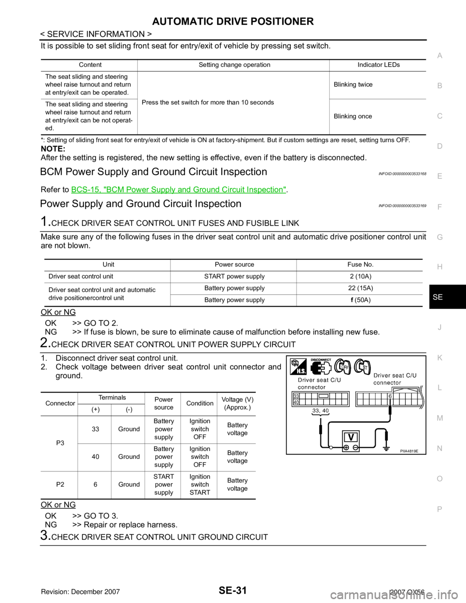
2.CHECK DRIVER SEAT CONTROL UNIT POWER SUPPLY CIRCUIT
1. Disconnect driver seat control unit.
2. Check voltage between driver seat control unit connector and
ground.
OK or NG
OK >> GO TO 3.
NG >> Repair or replace harness.
3.CHECK DRIVER SEAT CONTROL UNIT GROUND CIRCUIT
Content Setting change operation Indicator LEDs
The seat sliding and steering
wheel raise turnout and return
at entry/exit can be operated.
Press the set switch for more than 10 secondsBlinking twice
The seat sliding and steering
wheel raise turnout and return
at entry/exit can be not operat-
ed.Blinking once
Unit Power source Fuse No.
Driver seat control unit START power supply 2 (10A)
Driver seat control unit and automatic
drive positionercontrol unitBattery power supply 22 (15A)
Battery power supplyf (50A)
ConnectorTe r m i n a l s
Power
sourceConditionVoltage (V)
(Approx.)
(+) (-)
P333 GroundBattery
power
supplyIgnition
switch
OFFBattery
voltage
40 GroundBattery
power
supplyIgnition
switch
OFFBattery
voltage
P2 6 GroundSTART
power
supplyIgnition
switch
STARTBattery
voltage
PIIA4819E
Page 2874 of 3061
TF-52
< SERVICE INFORMATION >
TROUBLE DIAGNOSIS FOR SYSTEM
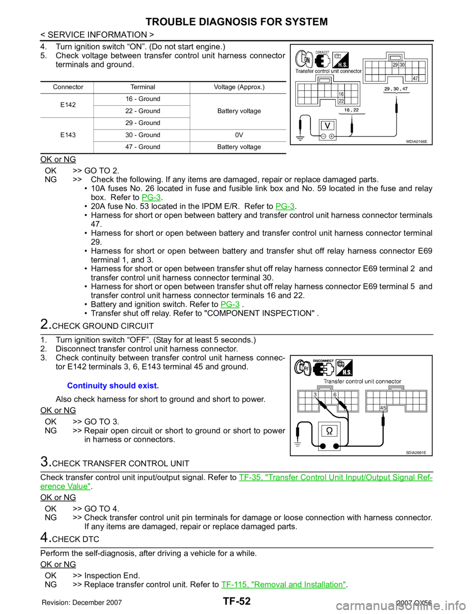
4. Turn ignition switch “ON”. (Do not start engine.)
5. Check voltage between transfer control unit harness connector
terminals and ground.
OK or NG
OK >> GO TO 2.
NG >> Check the following. If any items are damaged, repair or replace damaged parts.
• 10A fuses No. 26 located in fuse and fusible link box and No. 59 located in the fuse and relay
box. Refer to PG-3
.
• 20A fuse No. 53 located in the IPDM E/R. Refer to PG-3
.
• Harness for short or open between battery and transfer control unit harness connector terminals
47.
• Harness for short or open between battery and transfer control unit harness connector terminal
29.
• Harness for short or open between battery and transfer shut off relay harness connector E69
terminal 1, and 3.
• Harness for short or open between transfer shut off relay harness connector E69 terminal 2 and
transfer control unit harness connector terminal 30.
• Harness for short or open between transfer shut off relay harness connector E69 terminal 5 and
transfer control unit harness connector terminals 16 and 22.
• Battery and ignition switch. Refer to PG-3
.
• Transfer shut off relay. Refer to "COMPONENT INSPECTION" .
2.CHECK GROUND CIRCUIT
1. Turn ignition switch “OFF”. (Stay for at least 5 seconds.)
2. Disconnect transfer control unit harness connector.
3. Check continuity between transfer control unit harness connec-
tor E142 terminals 3, 6, E143 terminal 45 and ground.
Also check harness for short to ground and short to power.
OK or NG
OK >> GO TO 3.
NG >> Repair open circuit or short to ground or short to power
in harness or connectors.
3.CHECK TRANSFER CONTROL UNIT
Check transfer control unit input/output signal. Refer to TF-35, "
Transfer Control Unit Input/Output Signal Ref-
erence Value".
OK or NG
OK >> GO TO 4.
NG >> Check transfer control unit pin terminals for damage or loose connection with harness connector.
If any items are damaged, repair or replace damaged parts.
4.CHECK DTC
Perform the self-diagnosis, after driving a vehicle for a while.
OK or NG
OK >> Inspection End.
NG >> Replace transfer control unit. Refer to TF-115, "
Removal and Installation".
Connector Terminal Voltage (Approx.)
E14216 - Ground
Battery voltage 22 - Ground
E14329 - Ground
30 - Ground 0V
47 - Ground Battery voltage
WDIA0166E
Continuity should exist.
SDIA2691E
Page 2924 of 3061
TF-102
< SERVICE INFORMATION >
TROUBLE DIAGNOSIS FOR SYMPTOMS
TROUBLE DIAGNOSIS FOR SYMPTOMS
4WD Shift Indicator Lamp and 4LO Indicator Lamp Do Not Turn ONINFOID:0000000003532553
SYMPTOM:
4WD shift indicator lamp and 4LO indicator lamp do not turn ON for approx. 1 second when turning
ignition switch to “ON”.
DIAGNOSTIC PROCEDURE
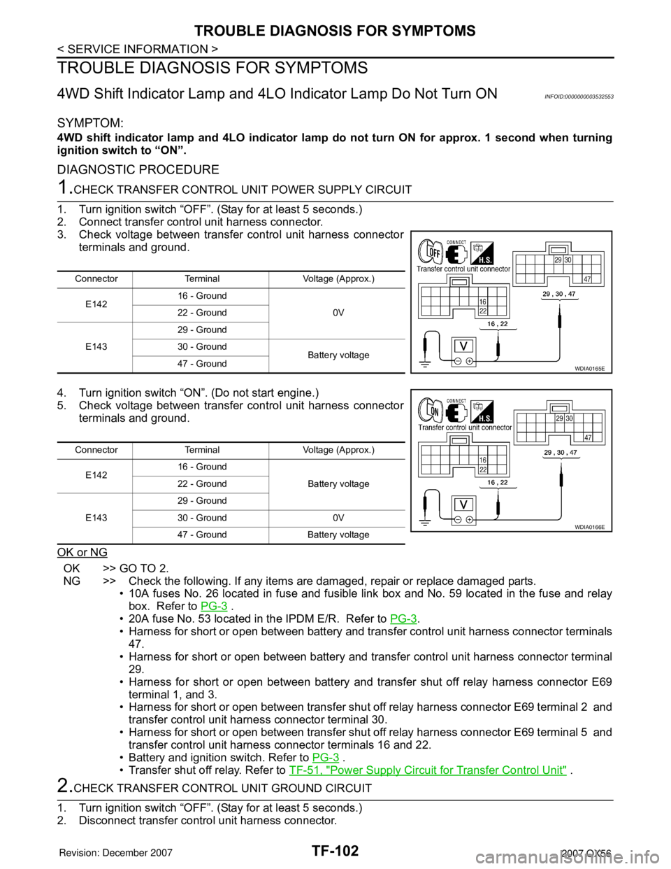
1.CHECK TRANSFER CONTROL UNIT POWER SUPPLY CIRCUIT
1. Turn ignition switch “OFF”. (Stay for at least 5 seconds.)
2. Connect transfer control unit harness connector.
3. Check voltage between transfer control unit harness connector
terminals and ground.
4. Turn ignition switch “ON”. (Do not start engine.)
5. Check voltage between transfer control unit harness connector
terminals and ground.
OK or NG
OK >> GO TO 2.
NG >> Check the following. If any items are damaged, repair or replace damaged parts.
• 10A fuses No. 26 located in fuse and fusible link box and No. 59 located in the fuse and relay
box. Refer to PG-3
.
• 20A fuse No. 53 located in the IPDM E/R. Refer to PG-3
.
• Harness for short or open between battery and transfer control unit harness connector terminals
47.
• Harness for short or open between battery and transfer control unit harness connector terminal
29.
• Harness for short or open between battery and transfer shut off relay harness connector E69
terminal 1, and 3.
• Harness for short or open between transfer shut off relay harness connector E69 terminal 2 and
transfer control unit harness connector terminal 30.
• Harness for short or open between transfer shut off relay harness connector E69 terminal 5 and
transfer control unit harness connector terminals 16 and 22.
• Battery and ignition switch. Refer to PG-3
.
• Transfer shut off relay. Refer to TF-51, "
Power Supply Circuit for Transfer Control Unit" .
2.CHECK TRANSFER CONTROL UNIT GROUND CIRCUIT
1. Turn ignition switch “OFF”. (Stay for at least 5 seconds.)
2. Disconnect transfer control unit harness connector.
Connector Terminal Voltage (Approx.)
E14216 - Ground
0V 22 - Ground
E14329 - Ground
30 - Ground
Battery voltage
47 - Ground
WDIA0165E
Connector Terminal Voltage (Approx.)
E14216 - Ground
Battery voltage 22 - Ground
E14329 - Ground
30 - Ground 0V
47 - Ground Battery voltage
WDIA0166E
Page 2927 of 3061
TROUBLE DIAGNOSIS FOR SYMPTOMS
TF-105
< SERVICE INFORMATION >
C
E
F
G
H
I
J
K
L
MA
B
TF
N
O
P
4WD warning lamp does not turn ON when turning ignition switch to “ON”.
DIAGNOSTIC PROCEDURE
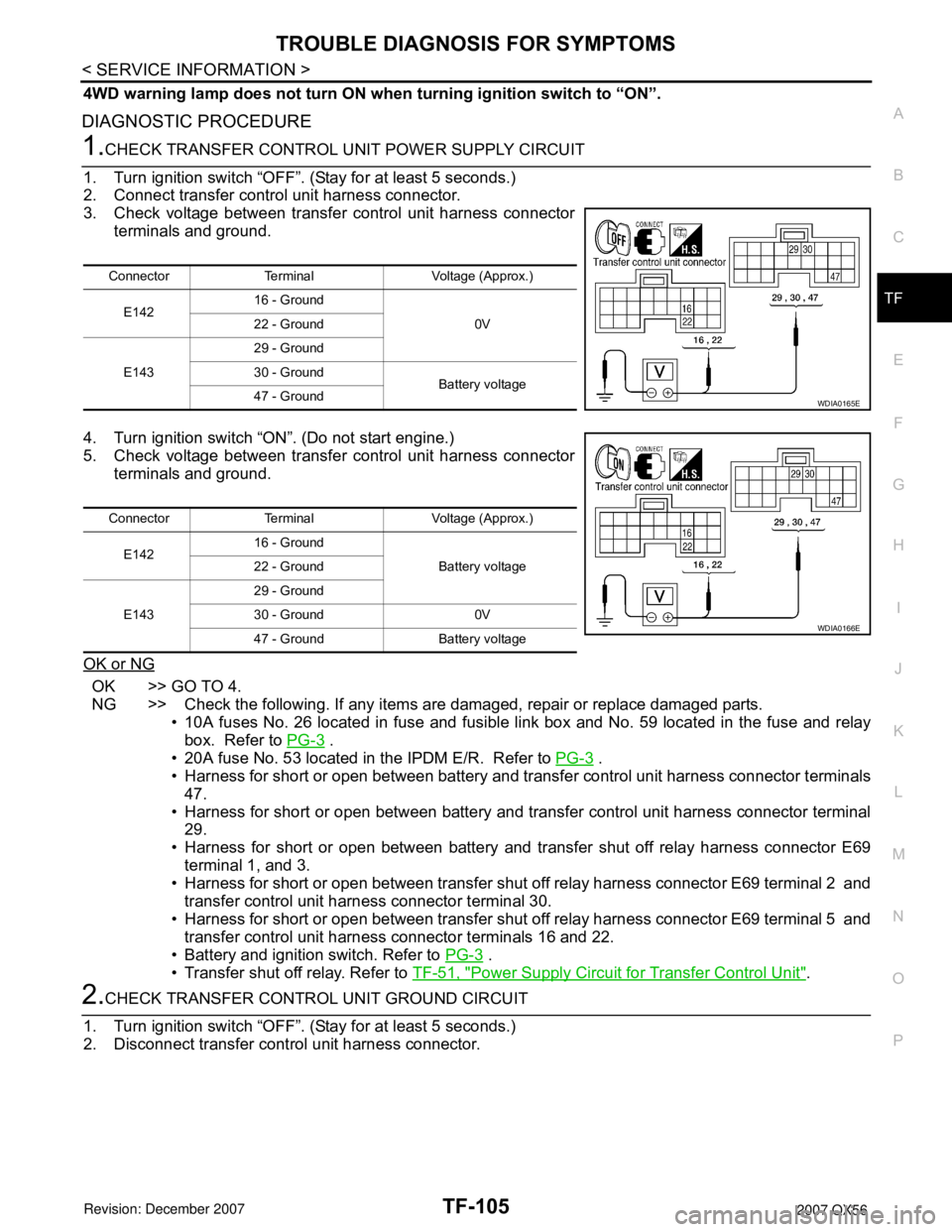
1.CHECK TRANSFER CONTROL UNIT POWER SUPPLY CIRCUIT
1. Turn ignition switch “OFF”. (Stay for at least 5 seconds.)
2. Connect transfer control unit harness connector.
3. Check voltage between transfer control unit harness connector
terminals and ground.
4. Turn ignition switch “ON”. (Do not start engine.)
5. Check voltage between transfer control unit harness connector
terminals and ground.
OK or NG
OK >> GO TO 4.
NG >> Check the following. If any items are damaged, repair or replace damaged parts.
• 10A fuses No. 26 located in fuse and fusible link box and No. 59 located in the fuse and relay
box. Refer to PG-3
.
• 20A fuse No. 53 located in the IPDM E/R. Refer to PG-3
.
• Harness for short or open between battery and transfer control unit harness connector terminals
47.
• Harness for short or open between battery and transfer control unit harness connector terminal
29.
• Harness for short or open between battery and transfer shut off relay harness connector E69
terminal 1, and 3.
• Harness for short or open between transfer shut off relay harness connector E69 terminal 2 and
transfer control unit harness connector terminal 30.
• Harness for short or open between transfer shut off relay harness connector E69 terminal 5 and
transfer control unit harness connector terminals 16 and 22.
• Battery and ignition switch. Refer to PG-3
.
• Transfer shut off relay. Refer to TF-51, "
Power Supply Circuit for Transfer Control Unit".
2.CHECK TRANSFER CONTROL UNIT GROUND CIRCUIT
1. Turn ignition switch “OFF”. (Stay for at least 5 seconds.)
2. Disconnect transfer control unit harness connector.
Connector Terminal Voltage (Approx.)
E14216 - Ground
0V 22 - Ground
E14329 - Ground
30 - Ground
Battery voltage
47 - Ground
WDIA0165E
Connector Terminal Voltage (Approx.)
E14216 - Ground
Battery voltage 22 - Ground
E14329 - Ground
30 - Ground 0V
47 - Ground Battery voltage
WDIA0166E