2007 INFINITI QX56 fuses
[x] Cancel search: fusesPage 650 of 3061
AV-110
< SERVICE INFORMATION >
NAVIGATION SYSTEM
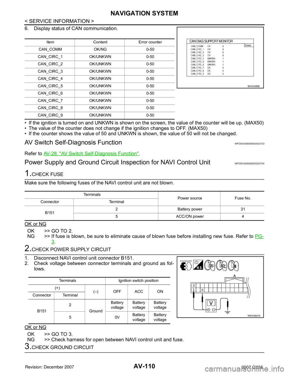
6. Display status of CAN communication.
• If the ignition is turned on and UNKWN is shown on the screen, the value of the counter will be up. (MAX50)
• The value of the counter does not change if the ignition changes to OFF. (MAX50)
• If the counter shows the value of 50 and UNKWN is shown, the value of 50 will not be changed.
AV Switch Self-Diagnosis FunctionINFOID:0000000003533723
Refer to AV-28, "AV Switch Self-Diagnosis Function".
Power Supply and Ground Circuit Inspection for NAVI Control UnitINFOID:0000000003533724
1.CHECK FUSE
Make sure the following fuses of the NAVI control unit are not blown.
OK or NG
OK >> GO TO 2.
NG >> If fuse is blown, be sure to eliminate cause of blown fuse before installing new fuse. Refer to PG-
3.
2.CHECK POWER SUPPLY CIRCUIT
1. Disconnect NAVI control unit connector B151.
2. Check voltage between connector terminals and ground as fol-
lows.
OK or NG
OK >> GO TO 3.
NG >> Check harness for open between NAVI control unit and fuse.
3.CHECK GROUND CIRCUIT
Item Content Error counter
CAN_COMM OK/NG 0-50
CAN_CIRC_1 OK/UNKWN 0-50
CAN_CIRC_2 OK/UNKWN 0-50
CAN_CIRC_3 OK/UNKWN 0-50
CAN_CIRC_4 OK/UNKWN 0-50
CAN_CIRC_5 OK/UNKWN 0-50
CAN_CIRC_6 OK/UNKWN 0-50
CAN_CIRC_7 OK/UNKWN 0-50
CAN_CIRC_8 OK/UNKWN 0-50
CAN_CIRC_9 OK/UNKWN 0-50
SKIA4288E
Te r m i n a l s
Power source Fuse No.
Connector Terminal
B1512 Battery power 31
5 ACC/ON power 4
Terminals Ignition switch position
(+)
(–) OFF ACC ON
Connector Terminal
B1512
GroundBattery
voltageBattery
voltageBattery
voltage
50VBattery
voltageBattery
voltage
WKIA4601E
Page 651 of 3061

NAVIGATION SYSTEM
AV-111
< SERVICE INFORMATION >
C
D
E
F
G
H
I
J
L
MA
B
AV
N
O
P
1. Turn ignition switch OFF.
2. Check continuity between the following NAVI control unit con-
nector terminals and ground.
OK or NG
OK >> Inspection End.
NG >> Repair or replace harness.
Power Supply and Ground Circuit Inspection for Display Control UnitINFOID:0000000003533725
1.CHECK FUSE
Make sure the following fuses of the display control unit are not blown.
OK or NG
OK >> GO TO 2.
NG >> If fuse is blown, be sure to eliminate cause of blown fuse before installing new fuse. Refer to PG-
3 .
2.CHECK POWER SUPPLY CIRCUIT
1. Disconnect display control unit connector M94.
2. Check voltage between connector terminals and ground as fol-
lows.
OK or NG
OK >> GO TO 3.
NG >> Check harness for open between display control unit and fuse.
3.CHECK GROUND CIRCUIT
Check continuity between the following display control unit connec-
tor terminals and ground.
OK or NG
OK >> Inspection End.
NG >> Repair or replace harness.
Te r m i n a l s
Ignition switch Continuity
Connector Terminal —
B151 1 Ground OFF Yes
WKIA4207E
Te r m i n a l s
Power source Fuse No.
Connector Terminal
M941 Battery power 31
10 ACC power 4
Terminals Ignition switch position
(+)
(–) OFF ACC ON
Connector Terminal
M941
GroundBattery
voltageBattery
voltageBattery
voltage
10 0VBattery
voltageBattery
voltage
WKIA1373E
Te r m i n a l s
Ignition switch Continuity
Connector Terminal —
M94 3 Ground OFF Yes
SKIA4293E
Page 653 of 3061

NAVIGATION SYSTEM
AV-113
< SERVICE INFORMATION >
C
D
E
F
G
H
I
J
L
MA
B
AV
N
O
P
1. Turn ignition switch OFF.
2. Check continuity between display unit harness connector M93
terminals 13, 14 and ground.
OK or NG
OK >> GO TO 6.
NG >> GO TO 5.
5. CHECK HARNESS
1. Disconnect display control unit connector M94.
2. Check continuity between display unit harness connector M93
terminals 13, 14 and display control unit harness connector M94
terminals 5, 7.
OK or NG
OK >> Replace display control unit. Refer to AV-145, "Removal
and Installation".
NG >> Repair harness.
6.CHECK GROUND CIRCUIT
Check continuity between display unit and ground as follows.
1.
OK or NG
OK >> Inspection End.
NG >> Repair harness.
Power Supply and Ground Circuit Inspection for AV SwitchINFOID:0000000003533727
1.CHECK FUSE
Make sure the following fuses of the AV switch are not blown.
OK or NG
OK >> GO TO 2.
NG >> If fuse is blown, be sure to eliminate cause of blown fuse before installing new fuse. Refer to PG-
3.
2.CHECK POWER SUPPLY CIRCUITContinuity should exist.
WKIA2079E
Continuity should exist.
WKIA2080E
Te r m i n a l s
Ignition
switchContinuity
Connector Terminal —
M93 1 Ground OFF Yes
WKIA1228E
Te r m i n a l s
Power source Fuse No.
Connector Terminal
M981 Battery power 31
2 ACC power 4
Page 702 of 3061

BCM (BODY CONTROL MODULE)
BCS-15
< SERVICE INFORMATION >
C
D
E
F
G
H
I
J
L
MA
B
BCS
N
O
P
BCM Power Supply and Ground Circuit InspectionINFOID:0000000003533601
1.CHECK FUSES AND FUSIBLE LINK
• Check 50A fusible link (letter f, located in the fuse and fusible link box).
• Check 10A fuse [No. 4, located in the fuse block (J/B)] and 15A fuse [No. 22, located in the fuse block (J/B)].
58 W/R Optical sensor Input ONWhen optical sensor is illumi-
nated3.1V or more
When optical sensor is not illu-
minated0.6V or less
59 GFront door lock as-
sembly LH actuator
(unlock)Output OFFOFF (neutral) 0V
ON (unlock) Battery voltage
60 G/B Turn signal LH Output ON Turn left ON
61 G/Y Turn signal RH Output ON Turn right ON
62 R/W Step lamp LH and RH Output OFFON (any door open) 0V
OFF (all doors closed) Battery voltage
63 LInterior room/map
lampOutput OFFAny door
switchON (open) 0V
OFF (closed) Battery voltage
65 VAll door lock actuators
(lock)Output OFFOFF (neutral) 0V
ON (lock) Battery voltage
66 G/YFront door lock actua-
tor RH, rear door lock
actuators LH/RH and
back door lock actua-
tor (unlock)Output OFFOFF (neutral) 0V
ON (unlock) Battery voltage
67 B Ground Input ON — 0V
68 W/LPower window power
supply (RAP)Output —Ignition switch ON Battery voltage
Within 45 seconds after igni-
tion switch OFFBattery voltage
More than 45 seconds after ig-
nition switch OFF0V
When front door LH or RH is
open or power window timer
operates0V
69 W/RPower window power
supplyOutput — — Battery voltage
70 W/B Battery power supply Input OFF — Battery voltage Te r m i n a lWire
colorSignal nameSignal
input/
outputMeasuring condition
Reference value or waveform
(Approx.) Ignition
switchOperation or condition
SKIA3009J
SKIA3009J
Page 1027 of 3061
DI-16
< SERVICE INFORMATION >
COMBINATION METERS
Perform self-diagnosis mode of combination meter. Refer to DI-12, "Self-Diagnosis Mode of Combination
Meter".
Does self-diagnosis mode operate normally?
YES >> GO TO 3.
NO >> Check combination meter power supply and ground circuit. Refer to DI-16, "
Power Supply and
Ground Circuit Inspection".
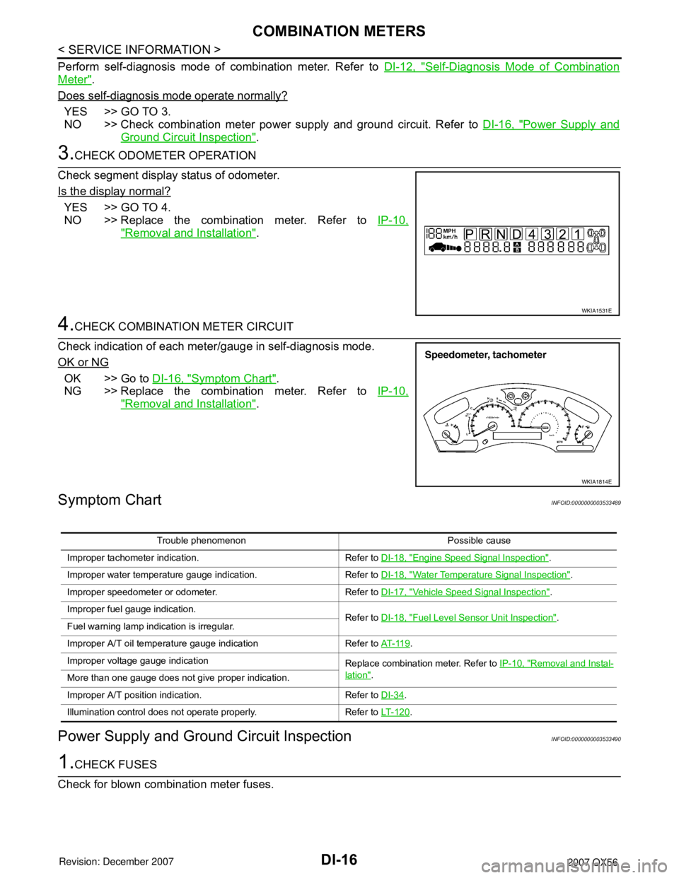
3.CHECK ODOMETER OPERATION
Check segment display status of odometer.
Is the display normal?
YES >> GO TO 4.
NO >> Replace the combination meter. Refer to IP-10,
"Removal and Installation".
4.CHECK COMBINATION METER CIRCUIT
Check indication of each meter/gauge in self-diagnosis mode.
OK or NG
OK >> Go to DI-16, "Symptom Chart".
NG >> Replace the combination meter. Refer to IP-10,
"Removal and Installation".
Symptom ChartINFOID:0000000003533489
Power Supply and Ground Circuit InspectionINFOID:0000000003533490
1.CHECK FUSES
Check for blown combination meter fuses.
WKIA1531E
WKIA1814E
Trouble phenomenon Possible cause
Improper tachometer indication. Refer to DI-18, "
Engine Speed Signal Inspection".
Improper water temperature gauge indication. Refer to DI-18, "
Water Temperature Signal Inspection".
Improper speedometer or odometer. Refer to DI-17, "
Vehicle Speed Signal Inspection".
Improper fuel gauge indication. Refer to DI-18, "
Fuel Level Sensor Unit Inspection".
Fuel warning lamp indication is irregular.
Improper A/T oil temperature gauge indication Refer to AT- 11 9
.
Improper voltage gauge indication Replace combination meter. Refer to IP-10, "
Removal and Instal-
lation".
More than one gauge does not give proper indication.
Improper A/T position indication. Refer to DI-34
.
Illumination control does not operate properly. Refer to LT- 1 2 0
.
Page 1078 of 3061
REAR VIEW MONITOR
DI-67
< SERVICE INFORMATION >
C
D
E
F
G
H
I
J
L
MA
B
DI
N
O
P
Power Supply and Ground Circuit InspectionINFOID:0000000003533546
1.CHECK FUSES
Check for blown rear view camera system fuses.
OK or NG
OK >> GO TO 2.
NG >> If fuse is blown, be sure to eliminate cause of problem before installing new fuse. Refer to PG-3
.
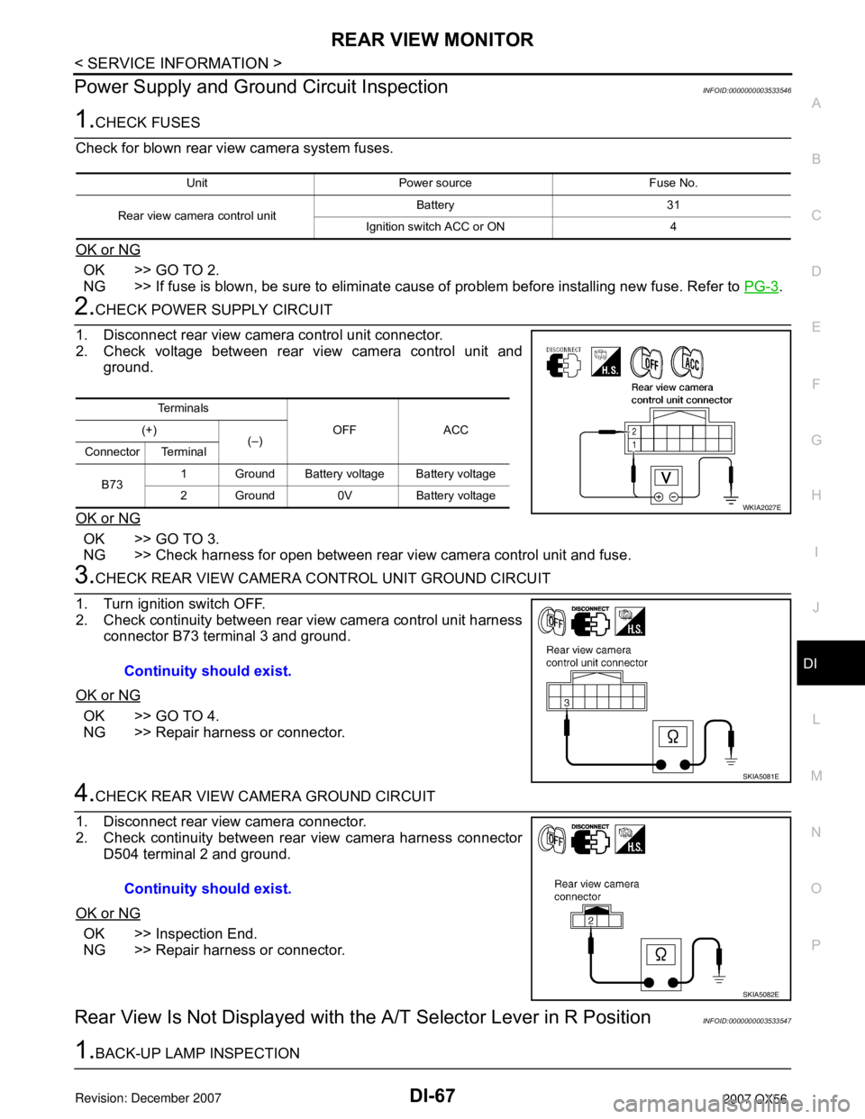
2.CHECK POWER SUPPLY CIRCUIT
1. Disconnect rear view camera control unit connector.
2. Check voltage between rear view camera control unit and
ground.
OK or NG
OK >> GO TO 3.
NG >> Check harness for open between rear view camera control unit and fuse.
3.CHECK REAR VIEW CAMERA CONTROL UNIT GROUND CIRCUIT
1. Turn ignition switch OFF.
2. Check continuity between rear view camera control unit harness
connector B73 terminal 3 and ground.
OK or NG
OK >> GO TO 4.
NG >> Repair harness or connector.
4.CHECK REAR VIEW CAMERA GROUND CIRCUIT
1. Disconnect rear view camera connector.
2. Check continuity between rear view camera harness connector
D504 terminal 2 and ground.
OK or NG
OK >> Inspection End.
NG >> Repair harness or connector.
Rear View Is Not Displayed with the A/T Selector Lever in R PositionINFOID:0000000003533547
1.BACK-UP LAMP INSPECTION
Unit Power source Fuse No.
Rear view camera control unitBattery 31
Ignition switch ACC or ON 4
Te r m i n a l s
OFF ACC (+)
(–)
Connector Terminal
B731 Ground Battery voltage Battery voltage
2 Ground 0V Battery voltage
WKIA2027E
Continuity should exist.
SKIA5081E
Continuity should exist.
SKIA5082E
Page 2087 of 3061
GW-68
< SERVICE INFORMATION >
REAR WINDOW DEFOGGER
REAR WINDOW DEFOGGER
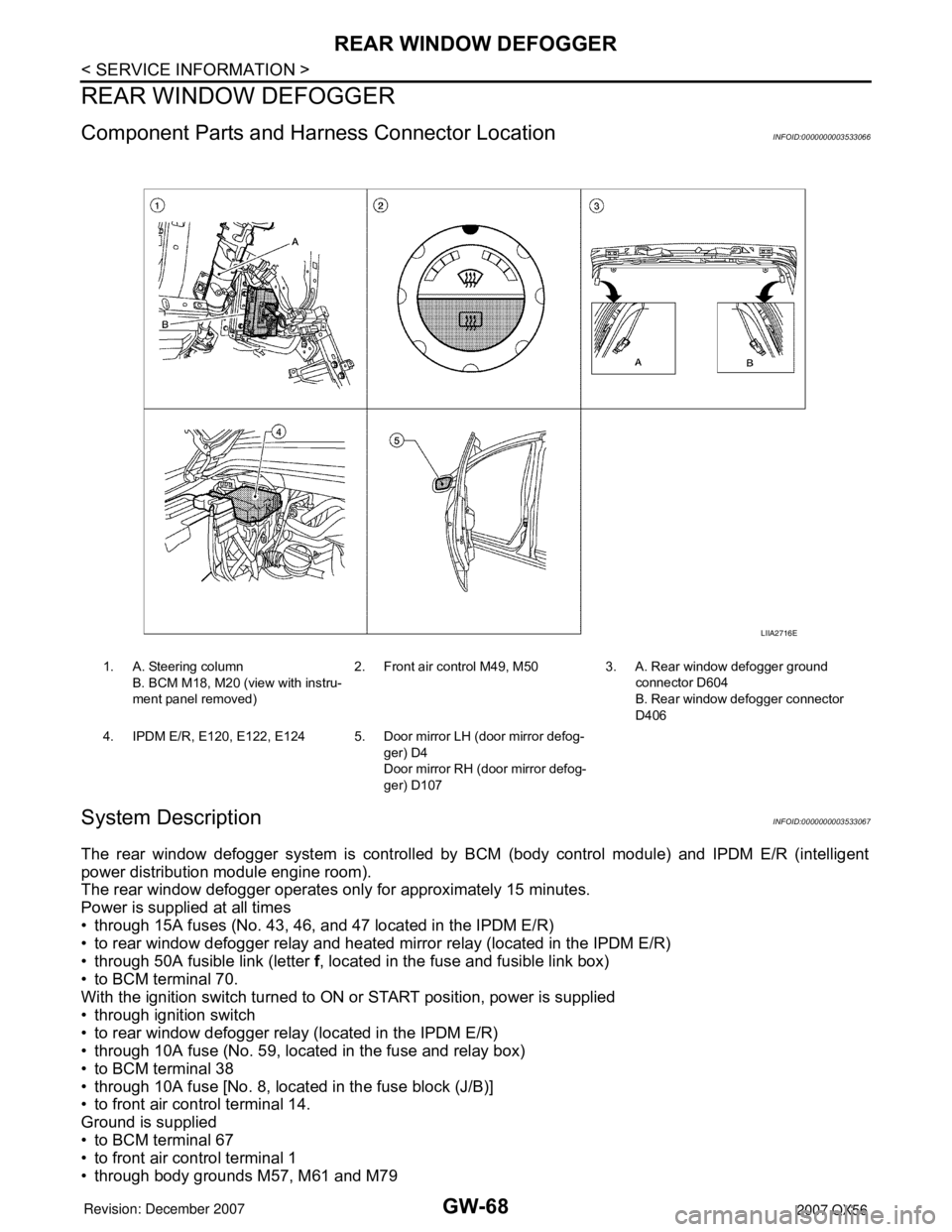
Component Parts and Harness Connector LocationINFOID:0000000003533066
System DescriptionINFOID:0000000003533067
The rear window defogger system is controlled by BCM (body control module) and IPDM E/R (intelligent
power distribution module engine room).
The rear window defogger operates only for approximately 15 minutes.
Power is supplied at all times
• through 15A fuses (No. 43, 46, and 47 located in the IPDM E/R)
• to rear window defogger relay and heated mirror relay (located in the IPDM E/R)
• through 50A fusible link (letter f, located in the fuse and fusible link box)
• to BCM terminal 70.
With the ignition switch turned to ON or START position, power is supplied
• through ignition switch
• to rear window defogger relay (located in the IPDM E/R)
• through 10A fuse (No. 59, located in the fuse and relay box)
• to BCM terminal 38
• through 10A fuse [No. 8, located in the fuse block (J/B)]
• to front air control terminal 14.
Ground is supplied
• to BCM terminal 67
• to front air control terminal 1
• through body grounds M57, M61 and M79
1. A. Steering column
B. BCM M18, M20 (view with instru-
ment panel removed)2. Front air control M49, M50 3. A. Rear window defogger ground
connector D604
B. Rear window defogger connector
D406
4. IPDM E/R, E120, E122, E124 5. Door mirror LH (door mirror defog-
ger) D4
Door mirror RH (door mirror defog-
ger) D107
LIIA2716E
Page 2095 of 3061
GW-76
< SERVICE INFORMATION >
REAR WINDOW DEFOGGER
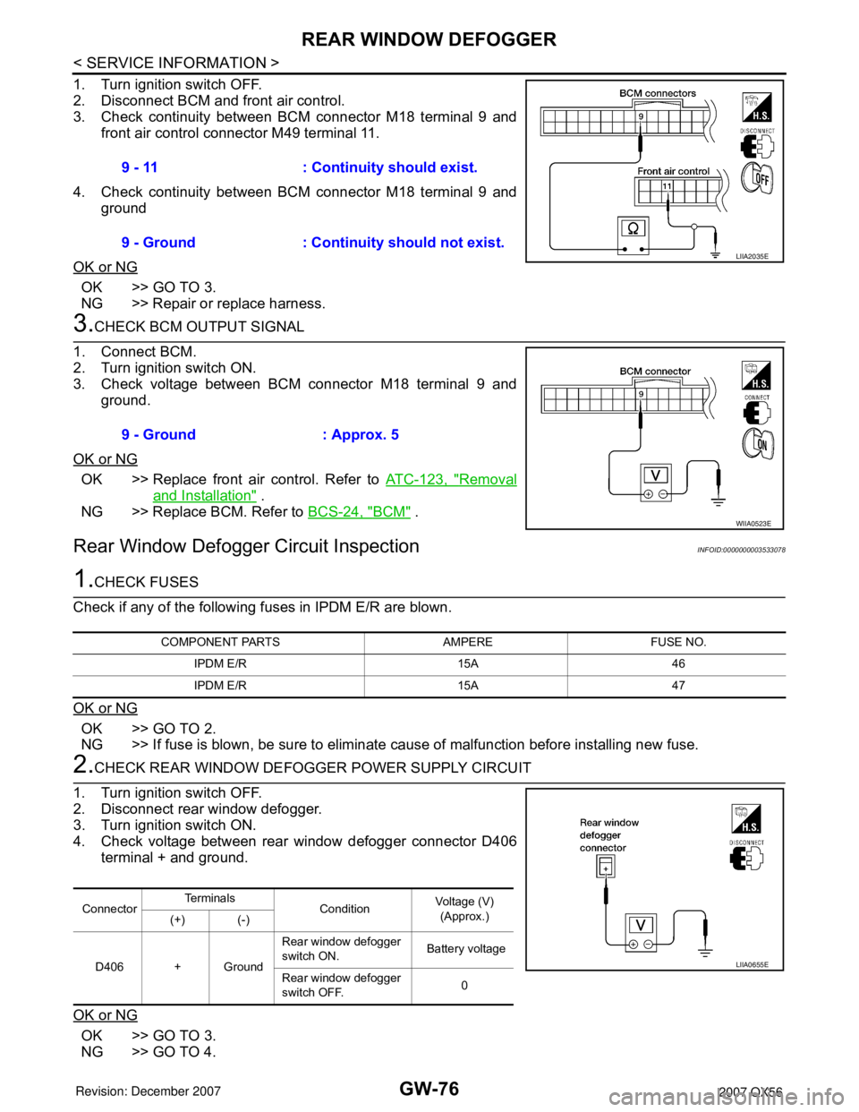
1. Turn ignition switch OFF.
2. Disconnect BCM and front air control.
3. Check continuity between BCM connector M18 terminal 9 and
front air control connector M49 terminal 11.
4. Check continuity between BCM connector M18 terminal 9 and
ground
OK or NG
OK >> GO TO 3.
NG >> Repair or replace harness.
3.CHECK BCM OUTPUT SIGNAL
1. Connect BCM.
2. Turn ignition switch ON.
3. Check voltage between BCM connector M18 terminal 9 and
ground.
OK or NG
OK >> Replace front air control. Refer to ATC-123, "Removal
and Installation" .
NG >> Replace BCM. Refer to BCS-24, "
BCM" .
Rear Window Defogger Circuit InspectionINFOID:0000000003533078
1.CHECK FUSES
Check if any of the following fuses in IPDM E/R are blown.
OK or NG
OK >> GO TO 2.
NG >> If fuse is blown, be sure to eliminate cause of malfunction before installing new fuse.
2.CHECK REAR WINDOW DEFOGGER POWER SUPPLY CIRCUIT
1. Turn ignition switch OFF.
2. Disconnect rear window defogger.
3. Turn ignition switch ON.
4. Check voltage between rear window defogger connector D406
terminal + and ground.
OK or NG
OK >> GO TO 3.
NG >> GO TO 4.9 - 11 : Continuity should exist.
9 - Ground : Continuity should not exist.
LIIA2035E
9 - Ground : Approx. 5
WIIA0523E
COMPONENT PARTS AMPERE FUSE NO.
IPDM E/R 15A 46
IPDM E/R 15A 47
ConnectorTe r m i n a l s
ConditionVoltage (V)
(Approx.)
(+) (-)
D406 + GroundRear window defogger
switch ON. Battery voltage
Rear window defogger
switch OFF.0
LIIA0655E