2007 INFINITI QX56 turn signal
[x] Cancel search: turn signalPage 1228 of 3061

DTC U1000, U1001 CAN COMMUNICATION LINE
EC-145
< SERVICE INFORMATION >
C
D
E
F
G
H
I
J
K
L
MA
EC
N
P O
DTC U1000, U1001 CAN COMMUNICATION LINE
DescriptionINFOID:0000000003531639
CAN (Controller Area Network) is a serial communication line for real time application. It is an on-vehicle mul-
tiplex communication line with high data communication speed and excellent error detection ability. Many elec-
tronic control units are equipped onto a vehicle, and each control unit shares information and links with other
control units during operation (not independent). In CAN communication, control units are connected with 2
communication lines (CAN H line, CAN L line) allowing a high rate of information transmission with less wiring.
Each control unit transmits/receives data but selectively reads required data only.
On Board Diagnosis LogicINFOID:0000000003531640
*1: This self-diagnosis has the one trip detection logic.
*2: The MIL will not light up for this self-diagnosis.
*3: This self-diagnosis has the one or two trip detection logic (Models with ICC)
DTC Confirmation ProcedureINFOID:0000000003531641
1. Turn ignition switch ON and wait at least 3 seconds.
2. Select “DATA MONITOR” mode with CONSULT-II.
3. If 1st trip DTC is detected, go to EC-146, "
Diagnosis Procedure".
DTC No. Trouble diagnosis name DTC detecting condition Possible cause
U1000*
1
1000*1
CAN communication lineWhen ECM is not transmitting or receiving CAN
communication signal of OBD (emission-relat-
ed diagnosis) for 2 seconds or more.• Harness or connectors
(CAN communication line is open or
shorted)
U1001*2*3
1001*2*3
When ECM is not transmitting or receiving CAN
communication signal other than OBD (emis-
sion related diagnosis) for 2 seconds or more.
Page 1236 of 3061
DTC P0011, P0021 IVT CONTROL
EC-153
< SERVICE INFORMATION >
C
D
E
F
G
H
I
J
K
L
MA
EC
N
P O
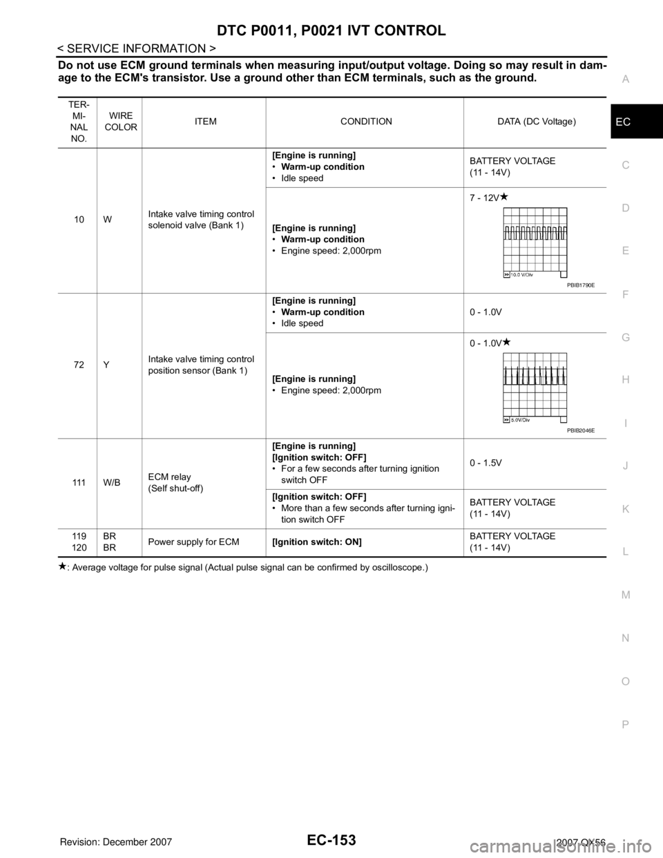
Do not use ECM ground terminals when measuring input/output voltage. Doing so may result in dam-
age to the ECM's transistor. Use a ground other than ECM terminals, such as the ground.
: Average voltage for pulse signal (Actual pulse signal can be confirmed by oscilloscope.)TER-
MI-
NAL
NO.WIRE
COLORITEM CONDITION DATA (DC Voltage)
10 WIntake valve timing control
solenoid valve (Bank 1)[Engine is running]
•Warm-up condition
• Idle speedBATTERY VOLTAGE
(11 - 14V)
[Engine is running]
•Warm-up condition
• Engine speed: 2,000rpm7 - 12V
72 YIntake valve timing control
position sensor (Bank 1)[Engine is running]
•Warm-up condition
• Idle speed0 - 1.0V
[Engine is running]
• Engine speed: 2,000rpm0 - 1.0V
111 W / BECM relay
(Self shut-off)[Engine is running]
[Ignition switch: OFF]
• For a few seconds after turning ignition
switch OFF0 - 1.5V
[Ignition switch: OFF]
• More than a few seconds after turning igni-
tion switch OFFBATTERY VOLTAGE
(11 - 14V)
11 9
120BR
BRPower supply for ECM[Ignition switch: ON]BATTERY VOLTAGE
(11 - 14V)
PBIB1790E
PBIB2046E
Page 1238 of 3061
DTC P0011, P0021 IVT CONTROL
EC-155
< SERVICE INFORMATION >
C
D
E
F
G
H
I
J
K
L
MA
EC
N
P O
: Average voltage for pulse signal (Actual pulse signal can be confirmed by oscilloscope.)
Diagnosis ProcedureINFOID:0000000003531653
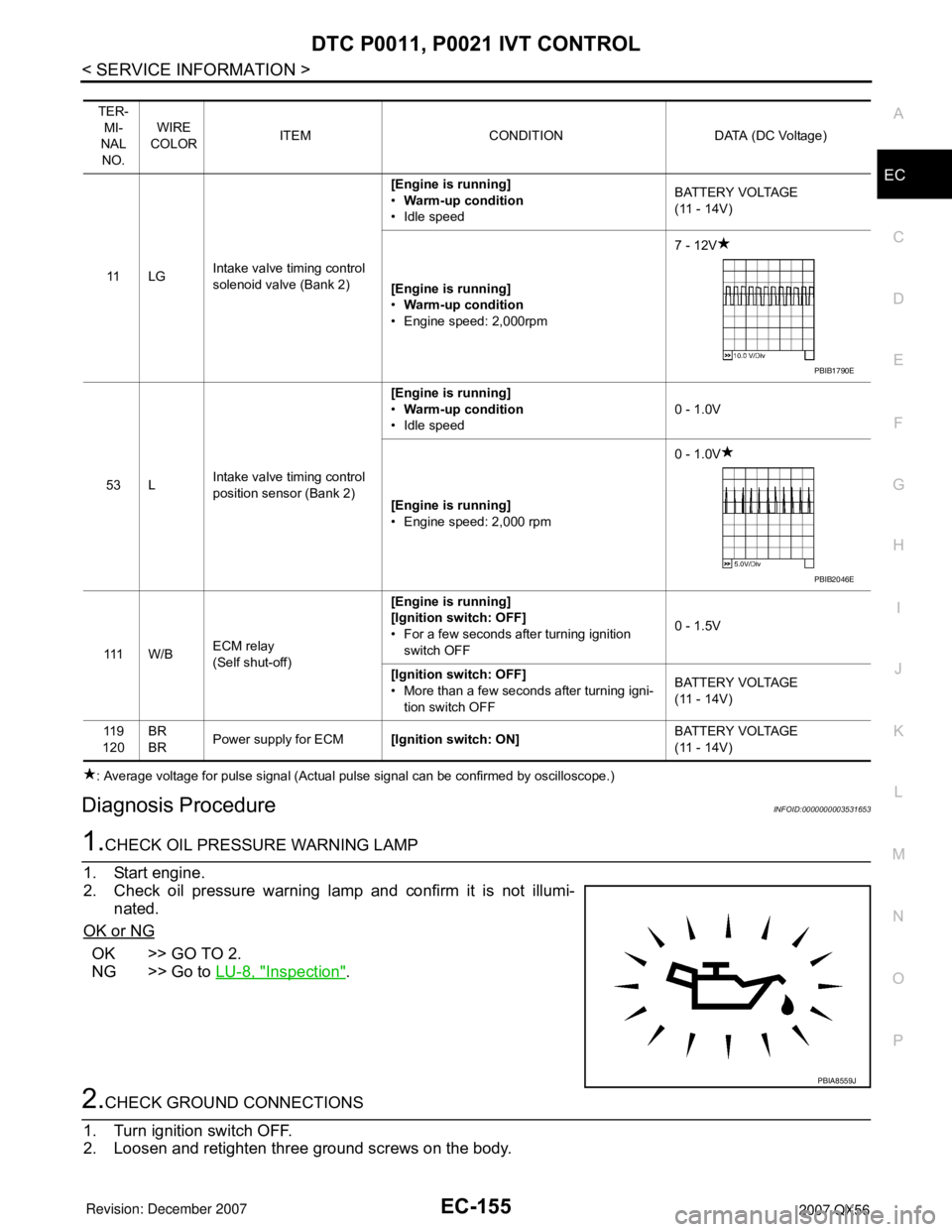
1.CHECK OIL PRESSURE WARNING LAMP
1. Start engine.
2. Check oil pressure warning lamp and confirm it is not illumi-
nated.
OK or NG
OK >> GO TO 2.
NG >> Go to LU-8, "
Inspection".
2.CHECK GROUND CONNECTIONS
1. Turn ignition switch OFF.
2. Loosen and retighten three ground screws on the body.
TER-
MI-
NAL
NO.WIRE
COLORITEM CONDITION DATA (DC Voltage)
11 L GIntake valve timing control
solenoid valve (Bank 2)[Engine is running]
•Warm-up condition
• Idle speedBATTERY VOLTAGE
(11 - 14V)
[Engine is running]
•Warm-up condition
• Engine speed: 2,000rpm7 - 12V
53 LIntake valve timing control
position sensor (Bank 2)[Engine is running]
•Warm-up condition
• Idle speed0 - 1.0V
[Engine is running]
• Engine speed: 2,000 rpm0 - 1.0V
111 W / BECM relay
(Self shut-off)[Engine is running]
[Ignition switch: OFF]
• For a few seconds after turning ignition
switch OFF0 - 1.5V
[Ignition switch: OFF]
• More than a few seconds after turning igni-
tion switch OFFBATTERY VOLTAGE
(11 - 14V)
11 9
120BR
BRPower supply for ECM[Ignition switch: ON]BATTERY VOLTAGE
(11 - 14V)
PBIB1790E
PBIB2046E
PBIA8559J
Page 1240 of 3061
DTC P0011, P0021 IVT CONTROL
EC-157
< SERVICE INFORMATION >
C
D
E
F
G
H
I
J
K
L
MA
EC
N
P O
5.CHECK INTAKE VALVE TIMING CONTROL POSITION SENSOR GROUND CIRCUIT FOR OPEN AND
SHORT
1. Turn ignition switch OFF.
2. Check harness continuity between intake valve timing control position sensor terminal 1 and ground.
Refer to Wiring Diagram.
3. Also check harness for short to power.
OK or NG
OK >> GO TO 7.
NG >> GO TO 6.
6.DETECT MALFUNCTIONING PART
Check the following.
• Harness connectors E2, F32
• Harness for open or short between intake valve timing control position sensor and ground
>> Repair open circuit or short to power in harness or connectors.
7.CHECK INTAKE VALVE TIMING CONTROL POSITION SENSOR INPUT SIGNAL CIRCUIT FOR OPEN
AND SHORT
1. Disconnect ECM harness connector.
2. Check harness continuity between the following;
ECM terminal 72 and intake valve timing control position sensor (Bank 1) terminal 2 or
ECM terminal 53 and intake valve timing control position sensor (Bank 2) terminal 2.
Refer to Wiring Diagram.
3. Also check harness for short to ground and short to power.
OK or NG
OK >> GO TO 8.
NG >> Repair open circuit or short to ground or short to power in harness or connectors.
8.CHECK INTAKE VALVE TIMING CONTROL POSITION SENSOR
Refer to EC-159, "
Component Inspection".
OK or NG
OK >> GO TO 9.
NG >> Replace malfunctioning intake valve timing control position sensor. Refer to EC-160
.
9.CHECK INTAKE VALVE TIMING CONTROL SOLENOID VALVE POWER SUPPLY CIRCUIT
1. Reconnect ECM harness connector.
2. Disconnect intake valve timing control solenoid valve harness connector.Continuity should exist.
Continuity should exist.
Page 1241 of 3061
EC-158
< SERVICE INFORMATION >
DTC P0011, P0021 IVT CONTROL
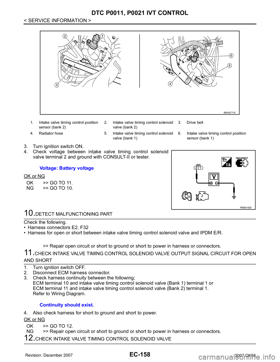
3. Turn ignition switch ON.
4. Check voltage between intake valve timing control solenoid
valve terminal 2 and ground with CONSULT-II or tester.
OK or NG
OK >> GO TO 11.
NG >> GO TO 10.
10.DETECT MALFUNCTIONING PART
Check the following.
• Harness connectors E2, F32
• Harness for open or short between intake valve timing control solenoid valve and IPDM E/R.
>> Repair open circuit or short to ground or short to power in harness or connectors.
11 .CHECK INTAKE VALVE TIMING CONTROL SOLENOID VALVE OUTPUT SIGNAL CIRCUIT FOR OPEN
AND SHORT
1. Turn ignition switch OFF.
2. Disconnect ECM harness connector.
3. Check harness continuity between the following;
ECM terminal 10 and intake valve timing control solenoid valve (Bank 1) terminal 1 or
ECM terminal 11 and intake valve timing control solenoid valve (Bank 2) terminal 1.
Refer to Wiring Diagram.
4. Also check harness for short to ground and short to power.
OK or NG
OK >> GO TO 12.
NG >> Repair open circuit or short to ground or short to power in harness or connectors.
12.CHECK INTAKE VALVE TIMING CONTROL SOLENOID VALVE
1. Intake valve timing control position
sensor (bank 2)2. Intake valve timing control solenoid
valve (bank 2)3. Drive belt
4. Radiator hose 5. Intake valve timing control solenoid
valve (bank 1)6. Intake valve timing control position
sensor (bank 1)
Voltage: Battery voltage
BBIA0771E
PBIB0192E
Continuity should exist.
Page 1246 of 3061

DTC P0031, P0032, P0051, P0052 A/F SENSOR 1 HEATER
EC-163
< SERVICE INFORMATION >
C
D
E
F
G
H
I
J
K
L
MA
EC
N
P O
DTC P0031, P0032, P0051, P0052 A/F SENSOR 1 HEATER
DescriptionINFOID:0000000003531656
SYSTEM DESCRIPTION
The ECM performs ON/OFF duty control of the A/F sensor 1 heater corresponding to the engine operating
condition to keep the temperature of A/F sensor 1 element at the specified range.
CONSULT-II Reference Value in Data Monitor ModeINFOID:0000000003531657
Specification data are reference values.
On Board Diagnosis LogicINFOID:0000000003531658
DTC Confirmation ProcedureINFOID:0000000003531659
NOTE:
If DTC Confirmation Procedure has been previously conducted, always turn ignition switch OFF and wait at
least 10 seconds before conducting the next test.
TESTING CONDITION:
Before performing the following procedure, confirm that battery voltage is between 10.5V and 16V at
idle.
WITH CONSULT-II
1. Turn ignition switch ON and select “DATA MONITOR” mode with
CONSULT-II.
2. Start engine and let it idle for at least 10 seconds.
3. If 1st trip DTC is detected, go to EC-167, "
Diagnosis Procedure".
Sensor Input Signal to ECM ECM function Actuator
Camshaft position sensor (PHASE)
Crankshaft position sensor (POS)Engine speed
Air fuel ratio (A/F) sensor 1
heater controlAir fuel ratio (A/F) sensor 1
heater
Mass air flow sensor Amount of intake air
MONITOR ITEM CONDITION SPECIFICATION
A/F S1 HTR (B1)
A/F S1 HTR (B2)• Engine: After warming up, idle the engine 4 - 100%
DTC No. Trouble diagnosis name DTC detecting condition Possible cause
P0031
0031
(Bank 1)
Air fuel ratio (A/F) sensor
1 heater control circuit lowThe current amperage in the air fuel ratio (A/F) sen-
sor 1 heater circuit is out of the normal range.
(An excessively low voltage signal is sent to ECM
through the air fuel ratio (A/F) sensor 1 heater.)• Harness or connectors
(The A/F sensor 1 heater circuit is
open or shorted.)
• A/F sensor 1 heater P0051
0051
(Bank 2)
P0032
0032
(Bank 1)Air fuel ratio (A/F) sensor
1 heater control circuit
highThe current amperage in the air fuel ratio (A/F) sen-
sor 1 heater circuit is out of the normal range.
(An excessively high voltage signal is sent to ECM
through the air fuel ratio (A/F) sensor 1 heater.)• Harness or connectors
(The A/F sensor 1 heater circuit is
shorted.)
• A/F sensor 1 heater P0052
0052
(Bank 2)
SEF058Y
Page 1250 of 3061
DTC P0031, P0032, P0051, P0052 A/F SENSOR 1 HEATER
EC-167
< SERVICE INFORMATION >
C
D
E
F
G
H
I
J
K
L
MA
EC
N
P O
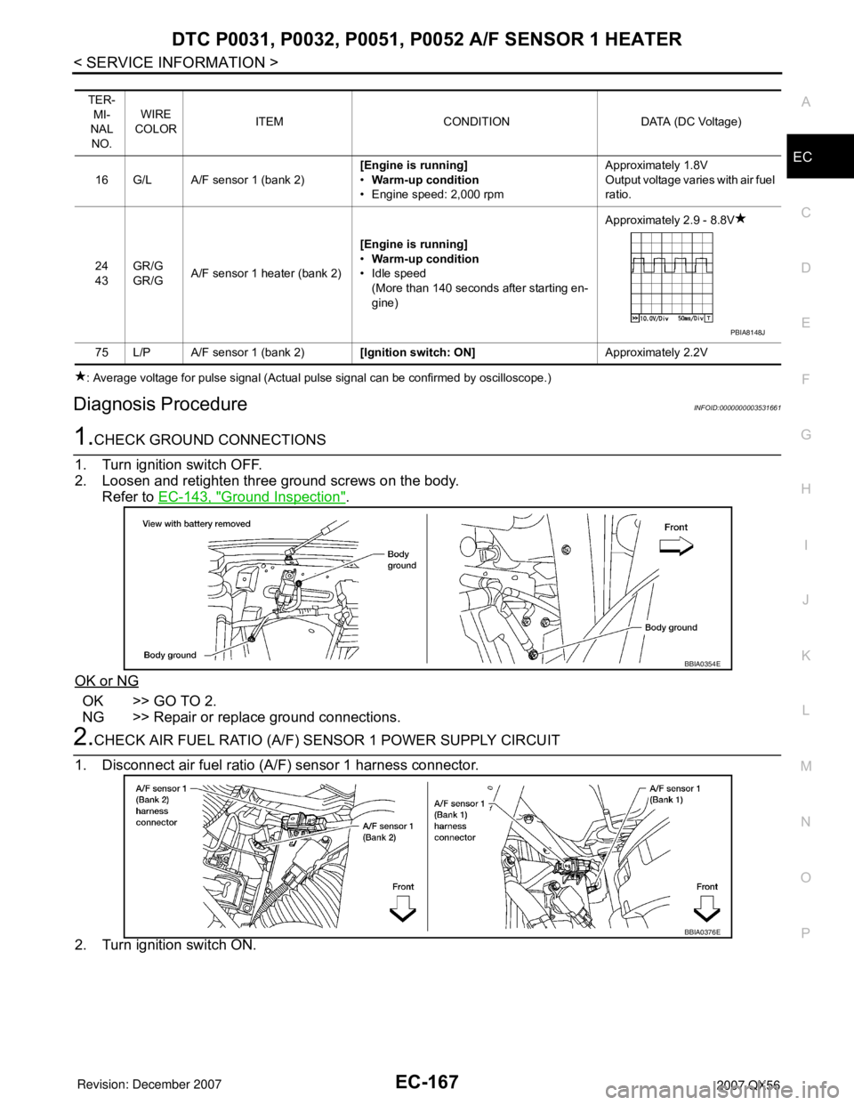
: Average voltage for pulse signal (Actual pulse signal can be confirmed by oscilloscope.)
Diagnosis ProcedureINFOID:0000000003531661
1.CHECK GROUND CONNECTIONS
1. Turn ignition switch OFF.
2. Loosen and retighten three ground screws on the body.
Refer to EC-143, "
Ground Inspection".
OK or NG
OK >> GO TO 2.
NG >> Repair or replace ground connections.
2.CHECK AIR FUEL RATIO (A/F) SENSOR 1 POWER SUPPLY CIRCUIT
1. Disconnect air fuel ratio (A/F) sensor 1 harness connector.
2. Turn ignition switch ON.
TER-
MI-
NAL
NO.WIRE
COLORITEM CONDITION DATA (DC Voltage)
16 G/L A/F sensor 1 (bank 2)[Engine is running]
•Warm-up condition
• Engine speed: 2,000 rpmApproximately 1.8V
Output voltage varies with air fuel
ratio.
24
43GR/G
GR/GA/F sensor 1 heater (bank 2)[Engine is running]
•Warm-up condition
• Idle speed
(More than 140 seconds after starting en-
gine)Approximately 2.9 - 8.8V
75 L/P A/F sensor 1 (bank 2)[Ignition switch: ON]Approximately 2.2V
PBIA8148J
BBIA0354E
BBIA0376E
Page 1251 of 3061
EC-168
< SERVICE INFORMATION >
DTC P0031, P0032, P0051, P0052 A/F SENSOR 1 HEATER
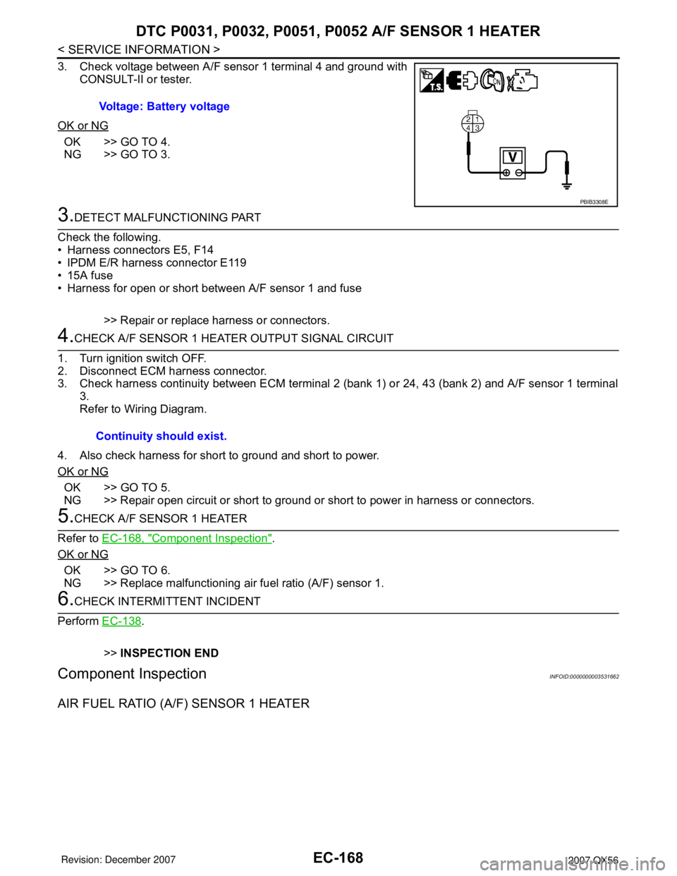
3. Check voltage between A/F sensor 1 terminal 4 and ground with
CONSULT-II or tester.
OK or NG
OK >> GO TO 4.
NG >> GO TO 3.
3.DETECT MALFUNCTIONING PART
Check the following.
• Harness connectors E5, F14
• IPDM E/R harness connector E119
• 15A fuse
• Harness for open or short between A/F sensor 1 and fuse
>> Repair or replace harness or connectors.
4.CHECK A/F SENSOR 1 HEATER OUTPUT SIGNAL CIRCUIT
1. Turn ignition switch OFF.
2. Disconnect ECM harness connector.
3. Check harness continuity between ECM terminal 2 (bank 1) or 24, 43 (bank 2) and A/F sensor 1 terminal
3.
Refer to Wiring Diagram.
4. Also check harness for short to ground and short to power.
OK or NG
OK >> GO TO 5.
NG >> Repair open circuit or short to ground or short to power in harness or connectors.
5.CHECK A/F SENSOR 1 HEATER
Refer to EC-168, "
Component Inspection".
OK or NG
OK >> GO TO 6.
NG >> Replace malfunctioning air fuel ratio (A/F) sensor 1.
6.CHECK INTERMITTENT INCIDENT
Perform EC-138
.
>>INSPECTION END
Component InspectionINFOID:0000000003531662
AIR FUEL RATIO (A/F) SENSOR 1 HEATER
Voltage: Battery voltage
PBIB3308E
Continuity should exist.