2007 INFINITI QX56 turn signal
[x] Cancel search: turn signalPage 1113 of 3061

EC-30
< SERVICE INFORMATION >
AUTOMATIC SPEED CONTROL DEVICE (ASCD)
AUTOMATIC SPEED CONTROL DEVICE (ASCD)
System DescriptionINFOID:0000000003531591
INPUT/OUTPUT SIGNAL CHART
*: This signal is sent to the ECM through CAN communication line
BASIC ASCD SYSTEM
Refer to Owner's Manual for ASCD operating instructions.
Automatic Speed Control Device (ASCD) allows a driver to keep vehicle at predetermined constant speed
without depressing accelerator pedal. Driver can set vehicle speed in advance between approximately 40 km/
h (25 MPH) and 144 km/h (89 MPH).
ECM controls throttle angle of electric throttle control actuator to regulate engine speed.
Operation status of ASCD is indicated by CRUISE indicator and SET indicator in combination meter. If any
malfunction occurs in ASCD system, it automatically deactivates control.
NOTE:
Always drive vehicle in safe manner according to traffic conditions and obey all traffic laws.
SET OPERATION
Press MAIN switch. (The CRUISE indicator in combination meter illuminates.)
When vehicle speed reaches a desired speed between approximately 40 km/h (25 MPH) and 144 km/h (89
MPH), press SET/COAST switch. (Then SET indicator in combination meter illuminates.)
ACCELERATE OPERATION
If the RESUME/ACCELERATE switch is pressed during cruise control driving, increase the vehicle speed until
the switch is released or vehicle speed reaches maximum speed controlled by the system.
And then ASCD will keep the new set speed.
CANCEL OPERATION
When any of following conditions exist, cruise operation will be canceled.
• CANCEL switch is pressed
• More than 2 switches at ASCD steering switch are pressed at the same time (Set speed will be cleared)
• Brake pedal is depressed
• Selector lever is changed to N, P, R position
• Vehicle speed decreased to 13 km/h (8 MPH) lower than the set speed
• VDC system is operated
When the ECM detects any of the following conditions, the ECM will cancel the cruise operation and inform
the driver by blinking indicator lamp.
• Engine coolant temperature is slightly higher than the normal operating temperature, CRUISE lamp may
blink slowly.
When the engine coolant temperature decreases to the normal operating temperature, CRUISE lamp will
stop blinking and the cruise operation will be able to work by pressing SET/COAST switch or RESUME/
ACCELERATE switch.
• Malfunction for some self-diagnoses regarding ASCD control: SET lamp will blink quickly.
If MAIN switch is turned to OFF during ASCD is activated, all of ASCD operations will be canceled and vehicle
speed memory will be erased.
COAST OPERATION
When the SET/COAST switch is pressed during cruise control driving, decrease vehicle set speed until the
switch is released. And then ASCD will keep the new set speed.
RESUME OPERATION
Sensor Input signal to ECM ECM function Actuator
ASCD brake switch Brake pedal operation
ASCD vehicle speed controlElectric throttle control
actuator Stop lamp switch Brake pedal operation
ASCD steering switch ASCD steering switch operation
Park/neutral position (PNP) switch Gear position
Wheel sensor Vehicle speed*
TCM Powertrain revolution*
Page 1160 of 3061

BASIC SERVICE PROCEDURE
EC-77
< SERVICE INFORMATION >
C
D
E
F
G
H
I
J
K
L
MA
EC
N
P O
Procedure After Replacing ECMINFOID:0000000003531611
When replacing ECM, the following procedure must be performed.
1. Perform initialization of IVIS (NATS) system and registration of all IVIS (NATS) ignition key IDs.
Refer to BL-117, "
ECM Re-communicating Function".
2. Perform EC-77, "
VIN Registration".
3. Perform EC-77, "
Accelerator Pedal Released Position Learning".
4. Perform EC-77, "
Throttle Valve Closed Position Learning".
5. Perform EC-78, "
Idle Air Volume Learning".
VIN RegistrationINFOID:0000000003531612
DESCRIPTION
VIN Registration is an operation to registering VIN in ECM. It must be performed each time ECM is replaced.
NOTE:
Accurate VIN which is registered in ECM may be required for Inspection & Maintenance (I/M).
OPERATION PROCEDURE
With CONSULT-II
1. Check the VIN of the vehicle and note it. Refer to GI-46.
2. Turn ignition switch ON and engine stopped.
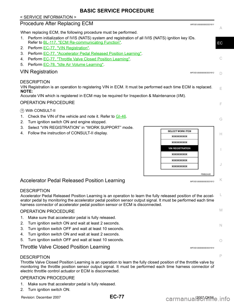
3. Select “VIN REGISTRATION” in “WORK SUPPORT” mode.
4. Follow the instruction of CONSULT-II display.
Accelerator Pedal Released Position LearningINFOID:0000000003531613
DESCRIPTION
Accelerator Pedal Released Position Learning is an operation to learn the fully released position of the accel-
erator pedal by monitoring the accelerator pedal position sensor output signal. It must be performed each time
harness connector of accelerator pedal position sensor or ECM is disconnected.
OPERATION PROCEDURE
1. Make sure that accelerator pedal is fully released.
2. Turn ignition switch ON and wait at least 2 seconds.
3. Turn ignition switch OFF and wait at least 10 seconds.
4. Turn ignition switch ON and wait at least 2 seconds.
5. Turn ignition switch OFF and wait at least 10 seconds.
Throttle Valve Closed Position LearningINFOID:0000000003531614
DESCRIPTION
Throttle Valve Closed Position Learning is an operation to learn the fully closed position of the throttle valve by
monitoring the throttle position sensor output signal. It must be performed each time harness connector of
electric throttle control actuator or ECM is disconnected.
OPERATION PROCEDURE
1. Make sure that accelerator pedal is fully released.
2. Turn ignition switch ON.
PBIB2242E
Page 1174 of 3061

TROUBLE DIAGNOSIS
EC-91
< SERVICE INFORMATION >
C
D
E
F
G
H
I
J
K
L
MA
EC
N
P O
1 - 6: The numbers refer to the order of inspection.
(continued on next page)
SYSTEM — ENGINE MECHANICAL & OTHER
Camshaft position sensor (PHASE) circuit 3 2EC-342
Vehicle speed signal circuit 2 3 3 3EC-429
Power steering pressure sensor circuit 2 3 3EC-435
ECM 22333333333EC-440,
EC-444
Intake valve timing control solenoid valve cir-
cuit32 13223 3EC-178
Park/Neutral position (PNP) switch circuit 3 3 3 3 3EC-452
Refrigerant pressure sensor circuit 2 3 3 4EC-638
Electrical load signal circuit 3EC-606
Air conditioner circuit 223333333 3 2AT C - 3 0
ABS actuator and electric unit (control unit) 4EC-467
,
EC-468
or BRC-11
SYMPTOM
Refer-
ence page
HARD/NO START/RESTART (EXCP. HA)
ENGINE STALL
HESITATION/SURGING/FLAT SPOT
SPARK KNOCK/DETONATION
LACK OF POWER/POOR ACCELERATION
HIGH IDLE/LOW IDLE
ROUGH IDLE/HUNTING
IDLING VIBRATION
SLOW/NO RETURN TO IDLE
OVERHEATS/WATER TEMPERATURE HIGH
EXCESSIVE FUEL CONSUMPTION
EXCESSIVE OIL CONSUMPTION
BATTERY DEAD (UNDER CHARGE)
Warranty symptom code AA AB AC AD AE AF AG AH AJ AK AL AM HA
Page 1175 of 3061

EC-92
< SERVICE INFORMATION >
TROUBLE DIAGNOSIS
SYMPTOM
Reference
page
HARD/NO START/RESTART (EXCP. HA)
ENGINE STALL
HESITATION/SURGING/FLAT SPOT
SPARK KNOCK/DETONATION
LACK OF POWER/POOR ACCELERATION
HIGH IDLE/LOW IDLE
ROUGH IDLE/HUNTING
IDLING VIBRATION
SLOW/NO RETURN TO IDLE
OVERHEATS/WATER TEMPERATURE HIGH
EXCESSIVE FUEL CONSUMPTION
EXCESSIVE OIL CONSUMPTION
BATTERY DEAD (UNDER CHARGE)
Warranty symptom code AA AB AC AD AE AF AG AH AJ AK AL AM HA
Fuel Fuel tank
5
5FL-10
Fuel piping 5 5 5 5 5 5FL-4
Va p o r l o c k—
Valve deposit
5 555 55 5—
Poor fuel (Heavy weight gasoline,
Low octane)—
Air Air duct
55555 5EM-15
Air cleanerEM-15
Air leakage from air duct
(Mass air flow sensor — electric
throttle control actuator)
5555EM-15
Electric throttle control actuatorEM-17
Air leakage from intake manifold/
Collector/GasketEM-17
Cranking Battery
111111
11SC-4
Generator circuitSC-15
Starter circuit 3SC-9
Signal plate 6EM-38
Park/Neutral position (PNP)
switch4AT- 9 9
Engine Cylinder head
55555 55 5EM-64
Cylinder head gasket 4 3
Cylinder block
66666 66 64
EM-78
Piston
Piston ring
Connecting rod
Bearing
Crankshaft
Va l v e
mecha-
nismTiming chain
55555 55 5EM-38
CamshaftEM-46
Intake valve timing controlEM-46
Intake valve
3EM-64
Exhaust valve
Page 1194 of 3061

TROUBLE DIAGNOSIS
EC-111
< SERVICE INFORMATION >
C
D
E
F
G
H
I
J
K
L
MA
EC
N
P O
: Average voltage for pulse signal (Actual pulse signal can be confirmed by oscilloscope.)
*:Before measuring the terminal voltage, confirm that the battery is fully charged. Refer to SC-4
.
CONSULT-II Function (ENGINE)INFOID:0000000003531626
FUNCTION
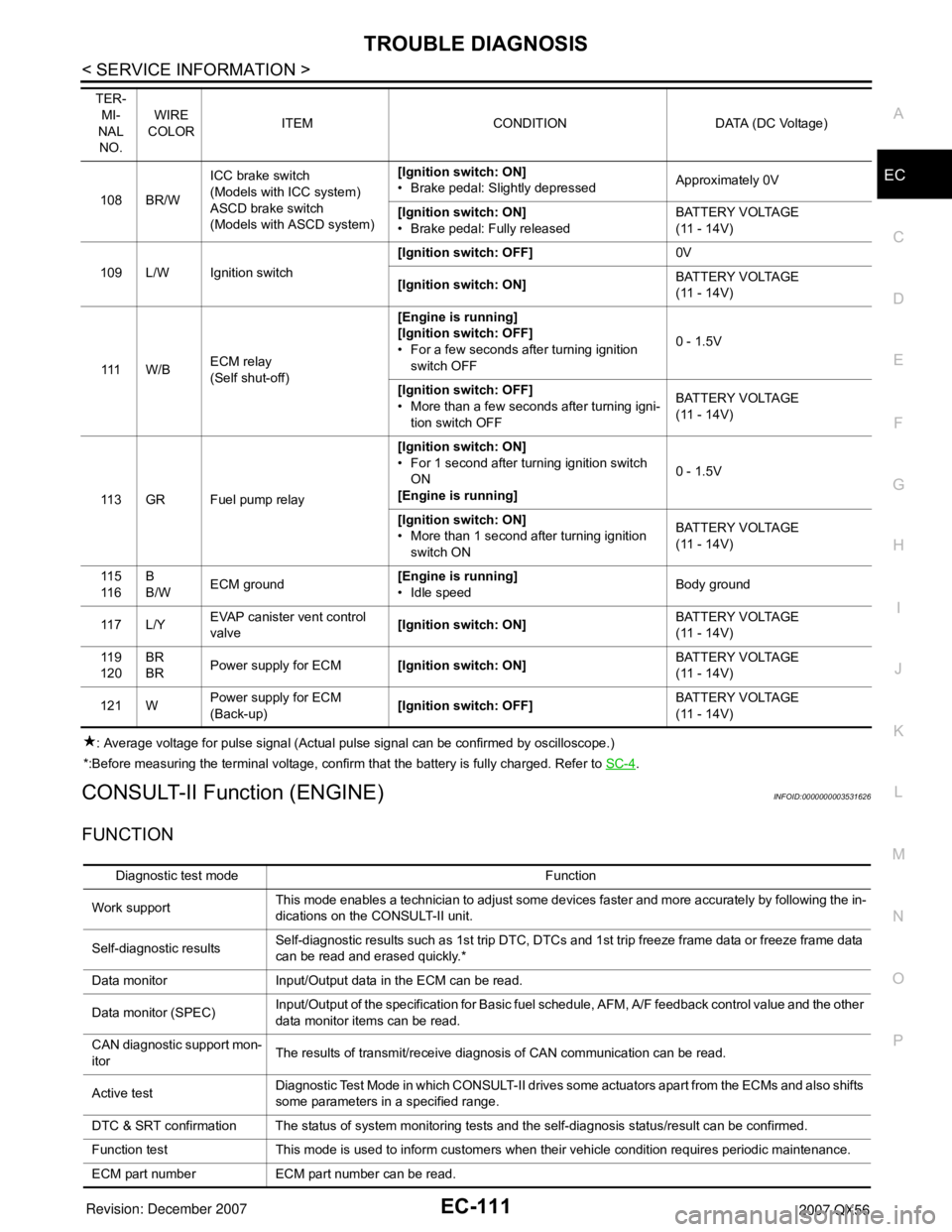
108 BR/WICC brake switch
(Models with ICC system)
ASCD brake switch
(Models with ASCD system)[Ignition switch: ON]
• Brake pedal: Slightly depressedApproximately 0V
[Ignition switch: ON]
• Brake pedal: Fully releasedBATTERY VOLTAGE
(11 - 14V)
109 L/W Ignition switch[Ignition switch: OFF]0V
[Ignition switch: ON]BATTERY VOLTAGE
(11 - 14V)
111 W / BECM relay
(Self shut-off)[Engine is running]
[Ignition switch: OFF]
• For a few seconds after turning ignition
switch OFF0 - 1.5V
[Ignition switch: OFF]
• More than a few seconds after turning igni-
tion switch OFFBATTERY VOLTAGE
(11 - 14V)
11 3 G R F u e l p u m p r e l a y[Ignition switch: ON]
• For 1 second after turning ignition switch
ON
[Engine is running]0 - 1.5V
[Ignition switch: ON]
• More than 1 second after turning ignition
switch ONBATTERY VOLTAGE
(11 - 14V)
11 5
11 6B
B/WECM ground[Engine is running]
• Idle speedBody ground
11 7 L / YEVAP canister vent control
valve[Ignition switch: ON]BATTERY VOLTAGE
(11 - 14V)
11 9
120BR
BRPower supply for ECM[Ignition switch: ON]BATTERY VOLTAGE
(11 - 14V)
121 WPower supply for ECM
(Back-up)[Ignition switch: OFF]BATTERY VOLTAGE
(11 - 14V) TER-
MI-
NAL
NO.WIRE
COLORITEM CONDITION DATA (DC Voltage)
Diagnostic test mode Function
Work supportThis mode enables a technician to adjust some devices faster and more accurately by following the in-
dications on the CONSULT-II unit.
Self-diagnostic resultsSelf-diagnostic results such as 1st trip DTC, DTCs and 1st trip freeze frame data or freeze frame data
can be read and erased quickly.*
Data monitor Input/Output data in the ECM can be read.
Data monitor (SPEC)Input/Output of the specification for Basic fuel schedule, AFM, A/F feedback control value and the other
data monitor items can be read.
CAN diagnostic support mon-
itorThe results of transmit/receive diagnosis of CAN communication can be read.
Active testDiagnostic Test Mode in which CONSULT-II drives some actuators apart from the ECMs and also shifts
some parameters in a specified range.
DTC & SRT confirmation The status of system monitoring tests and the self-diagnosis status/result can be confirmed.
Function test This mode is used to inform customers when their vehicle condition requires periodic maintenance.
ECM part number ECM part number can be read.
Page 1203 of 3061

EC-120
< SERVICE INFORMATION >
TROUBLE DIAGNOSIS
*: Leaving cooling fan OFF with CONSULT-II while engine is running may cause the engine to overheat.
DTC & SRT CONFIRMATION MODE
SRT STATUS Mode
For details, refer to EC-49, "Emission-related Diagnostic Information".
SRT WORK SUPPORT Mode
This mode enables a technician to drive a vehicle to set the SRT while monitoring the SRT status.
DTC WORK SUPPORT Mode
TEST ITEM CONDITION JUDGEMENT CHECK ITEM (REMEDY)
FUEL INJEC-
TION• Engine: Return to the original
trouble condition
• Change the amount of fuel injec-
tion using CONSULT-II.If trouble symptom disappears, see
CHECK ITEM.• Harness and connectors
• Fuel injector
• Air fuel ratio (A/F) sensor 1
IGNITION TIM-
ING• Engine: Return to the original
trouble condition
• Timing light: Set
• Retard the ignition timing using
CONSULT-II.If trouble symptom disappears, see
CHECK ITEM.• Perform Idle Air Volume Learning.
POWER BAL-
ANCE• Engine: After warming up, idle the
engine.
• A/C switch: OFF
• Selector lever: P or N
• Cut off each injector signal one at
a time using CONSULT-II.Engine runs rough or dies.• Harness and connectors
• Compression
• Fuel injector
• Power transistor
•Spark plug
• Ignition coil
COOLING FAN*• Ignition switch: ON
• Turn the cooling fan HI and OFF
using CONSULT-II.Cooling fan moves and stops.• Harness and connectors
• Cooling fan motor
• IPDM E/R
ENG COOLANT
TEMP• Engine: Return to the original
trouble condition
• Change the engine coolant tem-
perature using CONSULT-II.If trouble symptom disappears, see
CHECK ITEM.• Harness and connectors
• Engine coolant temperature sen-
sor
• Fuel injector
FUEL PUMP RE-
LAY• Ignition switch: ON
(Engine stopped)
• Turn the fuel pump relay ON and
OFF using CONSULT-II and lis-
ten to operating sound.Fuel pump relay makes the operat-
ing sound.• Harness and connectors
•Fuel pump relay
PURG VOL
CONT/V• Engine: After warming up, run en-
gine at 1,500 rpm.
• Change the EVAP canister purge
volume control solenoid valve
opening percent using CON-
SULT-II.Engine speed changes according to
the opening percent.• Harness and connectors
• Solenoid valve
FUEL/T TEMP
SEN• Change the fuel tank temperature using CONSULT-II.
VENT CON-
TROL/V• Ignition switch: ON
(Engine stopped)
• Turn solenoid valve ON and OFF
with the CONSULT-II and listen to
operating sound.Solenoid valve makes an operating
sound.• Harness and connectors
• Solenoid valve
V/T ASSIGN AN-
GLE• Engine: Return to the original
trouble condition
• Change intake valve timing using
CONSULT-II.If trouble symptom disappears, see
CHECK ITEM.• Harness and connectors
• Intake valve timing control sole-
noid valve
ALTERNATOR
DUTY•Engine: Idle
• Change duty ratio using CON-
SULT-II.Battery voltage changes.• Harness and connectors
• IPDM E/R
•Alternator
Page 1207 of 3061

EC-124
< SERVICE INFORMATION >
TROUBLE DIAGNOSIS
5. Perform each diagnostic service according to each service pro-
cedure.
For further information, see the GST Operation Manual of
the tool maker.
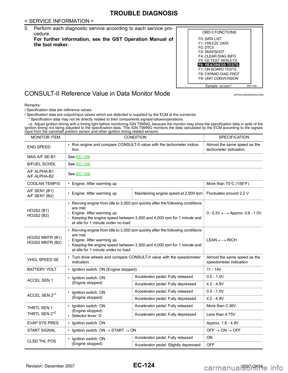
CONSULT-II Reference Value in Data Monitor ModeINFOID:0000000003531628
Remarks:
l Specification data are reference values.
l Specification data are output/input values which are detected or supplied by the ECM at the connector.
* Specification data may not be directly related to their components signals/values/operations.
i.e. Adjust ignition timing with a timing light before monitoring IGN TIMING, because the monitor may show the specification data in spite of the
ignition timing not being adjusted to the specification data. This IGN TIMING monitors the data calculated by the ECM according to the signals
input from the camshaft position sensor and other ignition timing related sensors.
SEF416S
MONITOR ITEM CONDITION SPECIFICATION
ENG SPEED• Run engine and compare CONSULT-II value with the tachometer indica-
tion.Almost the same speed as the
tachometer indication.
MAS A/F SE-B1 See EC-129
.
B/FUEL SCHDL See EC-129
.
A/F ALPHA-B1
A/F ALPHA-B2See EC-129
.
COOLAN TEMP/S • Engine: After warming up More than 70°C (158°F)
A/F SEN1 (B1)
A/F SEN1 (B2)• Engine: After warming up Maintaining engine speed at 2,000 rpm Fluctuates around 2.2 V
HO2S2 (B1)
HO2S2 (B2)• Revving engine from idle to 3,000 rpm quickly after the following conditions
are met.
- Engine: After warming up
- Keeping the engine speed between 3,500 and 4,000 rpm for 1 minute and
at idle for 1 minute under no load0 - 0.3V ←→ Approx. 0.6 - 1.0V
HO2S2 MNTR (B1)
HO2S2 MNTR (B2)• Revving engine from idle to 3,000 rpm quickly after the following conditions
are met.
- Engine: After warming up
- Keeping the engine speed between 3,500 and 4,000 rpm for 1 minute and
at idle for 1 minute under no loadLEAN ←→ RICH
VHCL SPEED SE• Turn drive wheels and compare CONSULT-II value with the speedometer
indication.Almost the same speed as the
speedometer indication
BATTERY VOLT • Ignition switch: ON (Engine stopped) 11 - 14V
ACCEL SEN 1• Ignition switch: ON
(Engine stopped)Accelerator pedal: Fully released 0.5 - 1.0V
Accelerator pedal: Fully depressed 4.2 - 4.8V
ACCEL SEN 2*
1• Ignition switch: ON
(Engine stopped)Accelerator pedal: Fully released 0.5 - 1.0V
Accelerator pedal: Fully depressed 4.2 - 4.8V
THRTL SEN 1
THRTL SEN 2*
2
• Ignition switch: ON
(Engine stopped)
• Selector lever: DAccelerator pedal: Fully released More than 0.36V
Accelerator pedal: Fully depressed Less than 4.75V
EVAP SYS PRES • Ignition switch: ON Approx. 1.8 - 4.8V
START SIGNAL • Ignition switch: ON → START → ON OFF → ON → OFF
CLSD THL POS• Ignition switch: ON
(Engine stopped)Accelerator pedal: Fully released ON
Accelerator pedal: Slightly depressed OFF
Page 1208 of 3061

TROUBLE DIAGNOSIS
EC-125
< SERVICE INFORMATION >
C
D
E
F
G
H
I
J
K
L
MA
EC
N
P O
AIR COND SIG• Engine: After warming up, idle the
engineAir conditioner switch: OFF OFF
Air conditioner switch: ON
(Compressor operates.)ON
P/N POSI SW • Ignition switch: ONSelector lever: P or N ON
Selector lever: Except above OFF
PW/ST SIGNAL• Engine: After warming up, idle the
engineSteering wheel: Not being turned
(Forward direction)OFF
Steering wheel: Being turned ON
LOAD SIGNAL • Ignition switch: ONRear window defogger switch is ON
and/or lighting switch is in 2nd.ON
Rear window defogger switch is OFF
and lighting switch is OFF.OFF
IGNITION SW • Ignition switch: ON → OFF → ON ON → OFF → ON
HEATER FAN SW• Engine: After warming up, idle the
engineHeater fan control switch: ON ON
Heater fan control switch: OFF OFF
BRAKE SW • Ignition switch: ONBrake pedal: Fully released OFF
Brake pedal: Slightly depressed ON
INJ PULSE-B1
INJ PULSE-B2• Engine: After warming up
• Selector lever: P or N
• Air conditioner switch: OFF
• No loadIdle 2.0 - 2.8 msec
2,000 rpm 1.9 - 2.9 msec
IGN TIMING• Engine: After warming up
• Selector lever: P or N
• Air conditioner switch: OFF
• No loadIdle 10° - 20° BTDC
2,000 rpm 25° - 45° BTDC
CAL/LD VALUE• Engine: After warming up
• Selector lever: P or N
• Air conditioner switch: OFF
• No loadIdle 14% - 33%
2,500 rpm 12% - 25%
MASS AIRFLOW• Engine: After warming up
• Selector lever: P or N
• Air conditioner switch: OFF
• No loadIdle 3.0 - 9.0 g·m/s
2,500 rpm 9.0 - 28.0 g·m/s
PURG VOL C/V• Engine: After warming up
• Selector lever: P or N
• Air conditioner switch: OFF
• No loadIdle
(Accelerator pedal: Not depressed
even slightly, after engine starting.)0%
2,000 rpm —
INT/V TIM (B1)
INT/V TIM (B2)• Engine: After warming up
• Selector lever: P or N
• Air conditioner switch: OFF
• No loadIdle−5° - 5°CA
2,000 rpm Approx. 0° - 20°CA
INT/V SOL (B1)
INT/V SOL (B2)• Engine: After warming up
• Selector lever: P or N
• Air conditioner switch: OFF
• No loadIdle 0% - 2%
2,000 rpm Approx. 25% - 50%
AIR COND RLY• Engine: After warming up, idle the
engineAir conditioner switch: OFF OFF
Air conditioner switch: ON
(Compressor: Operates)ON
FUEL PUMP RLY• For 1 second after turning ignition switch ON
• Engine running or crankingON
• Except above conditions OFF
VENT CONT/V • Ignition switch: ON OFF
THRTL RELAY • Ignition switch: ON ONMONITOR ITEM CONDITION SPECIFICATION