2007 INFINITI QX56 turn signal
[x] Cancel search: turn signalPage 1058 of 3061
REAR SONAR SYSTEM
DI-47
< SERVICE INFORMATION >
C
D
E
F
G
H
I
J
L
MA
B
DI
N
O
P
Ground is supplied
• to sonar control unit terminal 6
• through body grounds B7 and B19.
With the ignition switch in the ON or START position, and the transmission gear selector lever in the R posi-
tion, power is supplied
• to sonar control unit terminal 5
• from back-up lamp relay terminal 5.
With power and ground supplied, transmission gear selector lever in R position, and the rear sonar system
OFF switch ON, the rear sonar system will detect obstacles within 1.8 m (5.9 ft.) of the rear sonar sensors. The
vehicle operator is notified of obstacles by varied rate of tone from the sonar buzzer depending on distance of
obstacle being sensed.
REAR SONAR SYSTEM OFF SWITCH
With power and ground supplied to the sonar control unit, transmission gear selector lever in R position, the
sonar system can be disabled and the sonar buzzer silenced by momentarily pressing the rear sonar system
OFF switch. The rear sonar system OFF indicator lamp will be illuminated in the rear sonar system OFF
switch.
To disable the rear sonar system, ground is supplied
• to sonar control unit terminal 13
• through rear sonar system OFF switch terminal 1
• through rear sonar system OFF switch terminal 2
• from body grounds M57, M61, and M79.
To light the rear sonar system OFF indicator, power is supplied
• from sonar control unit terminal 4
• to the rear sonar system OFF switch terminal 5.
Ground is supplied
• to the rear sonar system OFF switch terminal 6
• from body grounds M57, M61, and M79.
The rear sonar system and buzzer will be disabled and the rear sonar system OFF indicator will be illuminated
until the ignition switch is turned OFF. When the ignition switch is turned ON, the rear sonar system will be
enabled. Depressing the rear sonar system OFF switch momentarily will enable the rear sonar system also.
Enabling the rear sonar system will cause the rear sonar system OFF indicator to go out.
SONAR BUZZER
With power supplied to the sonar control unit and the transmission gear selector lever in R position, a station-
ary object that is at least 7.0 cm (2.8 in.) wide and 1.0 m (39.0 in.) tall and that is closer than 1.8 meters (5.9 ft.)
will be detected by the rear sonar sensors, causing the sonar buzzer to sound a tone. As the vehicle moves
closer to the object, the rate of the tone will increase. When the object is less than 25.0 cm (10 in.) from the
rear bumper, the tone will sound continuously.
Power is supplied
• from sonar control unit terminal 7
• to sonar buzzer terminal +.
Ground is supplied
• to sonar buzzer terminal -
• from sonar control unit terminal 3.
REAR SONAR SENSOR
With power and ground supplied to the rear sonar sensors, the sonar sensors transmit a 38.4 kHz ultrasonic
signal. This signal is reflected back to the sensor by objects large enough and close enough to be detected.
The rear sonar sensors measure the time from the transmitted signal to the time the signal is reflected back
and sends this information to the sonar control unit.
Power is supplied
• from sonar control unit terminal 16
• to each rear sonar sensor terminal 1.
Ground is supplied
• to each rear sonar sensor terminal 3
• from sonar control unit terminal 15.
Signal is supplied
• from each rear sonar sensor terminal 2
• to sonar control unit terminals 9, 10, 11 and 12.
Page 1061 of 3061
DI-50
< SERVICE INFORMATION >
REAR SONAR SYSTEM
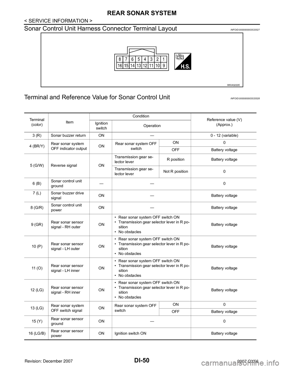
Sonar Control Unit Harness Connector Terminal Layout
INFOID:0000000003533527
Terminal and Reference Value for Sonar Control UnitINFOID:0000000003533528
WKIA5222E
Te r m i n a l
(color)ItemCondition
Reference value (V)
(Approx.) Ignition
switchOperation
3 (R) Sonar buzzer return ON — 0 - 12 (variable)
4 (BR/Y)Rear sonar system
OFF indicator outputONRear sonar system OFF
switch ON 0
OFF Battery voltage
5 (G/W) Reverse signal ONTransmission gear se-
lector leverR position Battery voltage
Transmission gear se-
lector leverNot R position 0
6 (B)Sonar control unit
ground —— 0
7 (L) Sonar buzzer drive
signalON — Battery voltage
8 (G/R)Sonar control unit
powerON — Battery voltage
9 (GR)Rear sonar sensor
signal - RH outerON• Rear sonar system OFF switch ON
• Transmission gear selector lever in R po-
sition
• No obstaclesBattery voltage
10 (P)Rear sonar sensor
signal - LH outerON• Rear sonar system OFF switch ON
• Transmission gear selector lever in R po-
sition
• No obstaclesBattery voltage
11 ( O )Rear sonar sensor
signal - LH innerON• Rear sonar system OFF switch ON
• Transmission gear selector lever in R po-
sition
• No obstaclesBattery voltage
12 (LG)Rear sonar sensor
signal - RH innerON• Rear sonar system OFF switch ON
• Transmission gear selector lever in R po-
sition
• No obstaclesBattery voltage
13 (LG)Rear sonar system
OFF switch signalONRear sonar system OFF
switchON 0
OFF Battery voltage
15 (Y)Rear sonar sensor
groundON — 0
16 (LG/B)Rear sonar sensor
powerON Ignition switch ON Battery voltage
Page 1076 of 3061
REAR VIEW MONITOR
DI-65
< SERVICE INFORMATION >
C
D
E
F
G
H
I
J
L
MA
B
DI
N
O
P
CONSULT-II START PROCEDURE
Refer to GI-36, "CONSULT-II Start Procedure".
WORK SUPPORT
Refer to DI-65, "Side Distance Guideline Correction" for details.
DATA MONITOR
Display Item List
Side Distance Guideline CorrectionINFOID:0000000003533545
This mode is used to modify the side distance guidelines if they are dislocated from the rear view monitor
image, because of variations of body/camera mounting conditions.
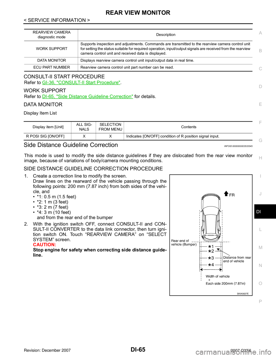
SIDE DISTANCE GUIDELINE CORRECTION PROCEDURE
1. Create a correction line to modify the screen.
Draw lines on the rearward of the vehicle passing through the
following points: 200 mm (7.87 inch) from both sides of the vehi-
cle, and
• *1: 0.5 m (1.5 feet)
• *2: 1 m (3 feet)
• *3: 2 m (7 feet)
• *4: 3 m (10 feet)
and from the rear end of the bumper
2. With the ignition switch OFF, connect CONSULT-II and CON-
SULT-II CONVERTER to the data link connector, then turn igni-
tion switch ON. Touch “REARVIEW CAMERA” on “SELECT
SYSTEM” screen.
CAUTION:
Stop engine for safety when correcting side distance guide-
line.
REARVIEW CAMERA
diagnostic modeDescription
WORK SUPPORTSupports inspection and adjustments. Commands are transmitted to the rearview camera control unit
for setting the status suitable for required operation, input/output signals are received from the rearview
camera control unit and received data is displayed.
DATA MONITOR Displays rearview camera control unit input/output data in real time.
ECU PART NUMBER Rearview camera control unit part number can be read.
Display item [Unit]ALL SIG-
NALSSELECTION
FROM MENUContents
R POSI SIG [ON/OFF] X X Indicates [ON/OFF] condition of R position signal input.
SKIA5637E
Page 1079 of 3061

DI-68
< SERVICE INFORMATION >
REAR VIEW MONITOR
1. Turn ignition switch ON.
2. Shift A/T selector lever to R position.
Does back-up lamp illuminate?
YES >> GO TO 2.
NO >> Check back-up lamp system. Refer to LT- 8 0
.
2.CHECK REVERSE POSITION INPUT SIGNAL
With CONSULT-II
Select “DATA MONITOR” of “REARVIEW CAMERA”. Operate igni-
tion switch with “R POSI SIG” of “DATA MONITOR” and check oper-
ate status.
Without CONSULT-II
1. Turn ignition switch OFF.
2. Disconnect rear view camera control unit connector.
3. Turn ignition switch ON.
4. Shift A/T selector lever to R position.
5. Check voltage between rear view camera control unit harness
connector B73 terminal 4 and ground.
OK or NG
OK >> GO TO 3.
NG >> Check harness for open or short between rear view
camera control unit and back-up lamp relay.
3.CHECK DISPLAY CONTROL UNIT OUTPUT SIGNAL
1. Turn ignition switch OFF.
2. Disconnect rear view camera control unit connector.
3. Turn ignition switch ON.
4. Check voltage between rear view camera control unit harness
connector B73 terminal 5 and ground.
OK or NG
OK >> GO TO 5.
NG >> GO TO 4.
4.CHECK DISPLAY CONTROL UNIT CIRCUIT
SKIA7147E
Battery voltage should exist.
SKIA5086E
Voltage : Approx. 5V
SKIA7148E
Page 1080 of 3061
REAR VIEW MONITOR
DI-69
< SERVICE INFORMATION >
C
D
E
F
G
H
I
J
L
MA
B
DI
N
O
P
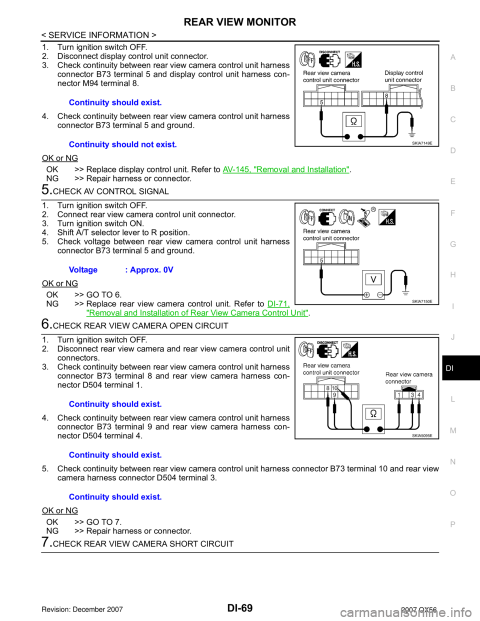
1. Turn ignition switch OFF.
2. Disconnect display control unit connector.
3. Check continuity between rear view camera control unit harness
connector B73 terminal 5 and display control unit harness con-
nector M94 terminal 8.
4. Check continuity between rear view camera control unit harness
connector B73 terminal 5 and ground.
OK or NG
OK >> Replace display control unit. Refer to AV-145, "Removal and Installation".
NG >> Repair harness or connector.
5.CHECK AV CONTROL SIGNAL
1. Turn ignition switch OFF.
2. Connect rear view camera control unit connector.
3. Turn ignition switch ON.
4. Shift A/T selector lever to R position.
5. Check voltage between rear view camera control unit harness
connector B73 terminal 5 and ground.
OK or NG
OK >> GO TO 6.
NG >> Replace rear view camera control unit. Refer to DI-71,
"Removal and Installation of Rear View Camera Control Unit".
6.CHECK REAR VIEW CAMERA OPEN CIRCUIT
1. Turn ignition switch OFF.
2. Disconnect rear view camera and rear view camera control unit
connectors.
3. Check continuity between rear view camera control unit harness
connector B73 terminal 8 and rear view camera harness con-
nector D504 terminal 1.
4. Check continuity between rear view camera control unit harness
connector B73 terminal 9 and rear view camera harness con-
nector D504 terminal 4.
5. Check continuity between rear view camera control unit harness connector B73 terminal 10 and rear view
camera harness connector D504 terminal 3.
OK or NG
OK >> GO TO 7.
NG >> Repair harness or connector.
7.CHECK REAR VIEW CAMERA SHORT CIRCUITContinuity should exist.
Continuity should not exist.
SKIA7149E
Voltage : Approx. 0V
SKIA7150E
Continuity should exist.
Continuity should exist.
Continuity should exist.
SKIA5095E
Page 1081 of 3061
DI-70
< SERVICE INFORMATION >
REAR VIEW MONITOR
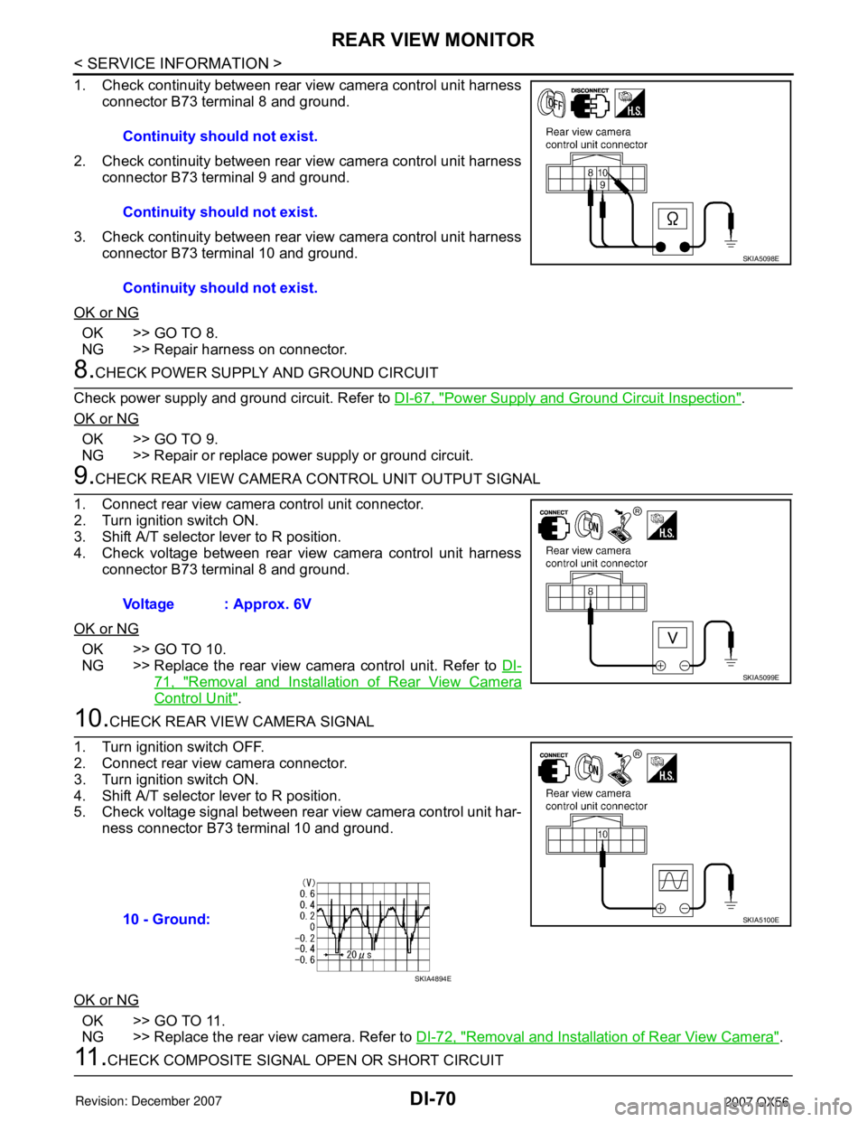
1. Check continuity between rear view camera control unit harness
connector B73 terminal 8 and ground.
2. Check continuity between rear view camera control unit harness
connector B73 terminal 9 and ground.
3. Check continuity between rear view camera control unit harness
connector B73 terminal 10 and ground.
OK or NG
OK >> GO TO 8.
NG >> Repair harness on connector.
8.CHECK POWER SUPPLY AND GROUND CIRCUIT
Check power supply and ground circuit. Refer to DI-67, "
Power Supply and Ground Circuit Inspection".
OK or NG
OK >> GO TO 9.
NG >> Repair or replace power supply or ground circuit.
9.CHECK REAR VIEW CAMERA CONTROL UNIT OUTPUT SIGNAL
1. Connect rear view camera control unit connector.
2. Turn ignition switch ON.
3. Shift A/T selector lever to R position.
4. Check voltage between rear view camera control unit harness
connector B73 terminal 8 and ground.
OK or NG
OK >> GO TO 10.
NG >> Replace the rear view camera control unit. Refer to DI-
71, "Removal and Installation of Rear View Camera
Control Unit".
10.CHECK REAR VIEW CAMERA SIGNAL
1. Turn ignition switch OFF.
2. Connect rear view camera connector.
3. Turn ignition switch ON.
4. Shift A/T selector lever to R position.
5. Check voltage signal between rear view camera control unit har-
ness connector B73 terminal 10 and ground.
OK or NG
OK >> GO TO 11.
NG >> Replace the rear view camera. Refer to DI-72, "
Removal and Installation of Rear View Camera".
11 .CHECK COMPOSITE SIGNAL OPEN OR SHORT CIRCUITContinuity should not exist.
Continuity should not exist.
Continuity should not exist.
SKIA5098E
Voltage : Approx. 6V
SKIA5099E
10 - Ground:SKIA5100E
SKIA4894E
Page 1082 of 3061
REAR VIEW MONITOR
DI-71
< SERVICE INFORMATION >
C
D
E
F
G
H
I
J
L
MA
B
DI
N
O
P
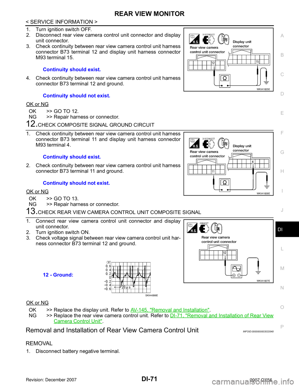
1. Turn ignition switch OFF.
2. Disconnect rear view camera control unit connector and display
unit connector.
3. Check continuity between rear view camera control unit harness
connector B73 terminal 12 and display unit harness connector
M93 terminal 15.
4. Check continuity between rear view camera control unit harness
connector B73 terminal 12 and ground.
OK or NG
OK >> GO TO 12.
NG >> Repair harness or connector.
12.CHECK COMPOSITE SIGNAL GROUND CIRCUIT
1. Check continuity between rear view camera control unit harness
connector B73 terminal 11 and display unit harness connector
M93 terminal 4.
2. Check continuity between rear view camera control unit harness
connector B73 terminal 11 and ground.
OK or NG
OK >> GO TO 13.
NG >> Repair harness or connector.
13.CHECK REAR VIEW CAMERA CONTROL UNIT COMPOSITE SIGNAL
1. Connect rear view camera control unit connector and display
unit connector.
2. Turn ignition switch ON.
3. Check voltage signal between rear view camera control unit har-
ness connector B73 terminal 12 and ground.
OK or NG
OK >> Replace the display unit. Refer to AV-145, "Removal and Installation".
NG >> Replace the rear view camera control unit. Refer to DI-71, "
Removal and Installation of Rear View
Camera Control Unit".
Removal and Installation of Rear View Camera Control UnitINFOID:0000000003533548
REMOVAL
1. Disconnect battery negative terminal.Continuity should exist.
Continuity should not exist.
WKIA1825E
Continuity should exist.
Continuity should not exist.
WKIA1826E
12 - Ground:
WKIA1827E
SKIA4896E
Page 1112 of 3061
AIR CONDITIONING CUT CONTROL
EC-29
< SERVICE INFORMATION >
C
D
E
F
G
H
I
J
K
L
MA
EC
N
P O
AIR CONDITIONING CUT CONTROL
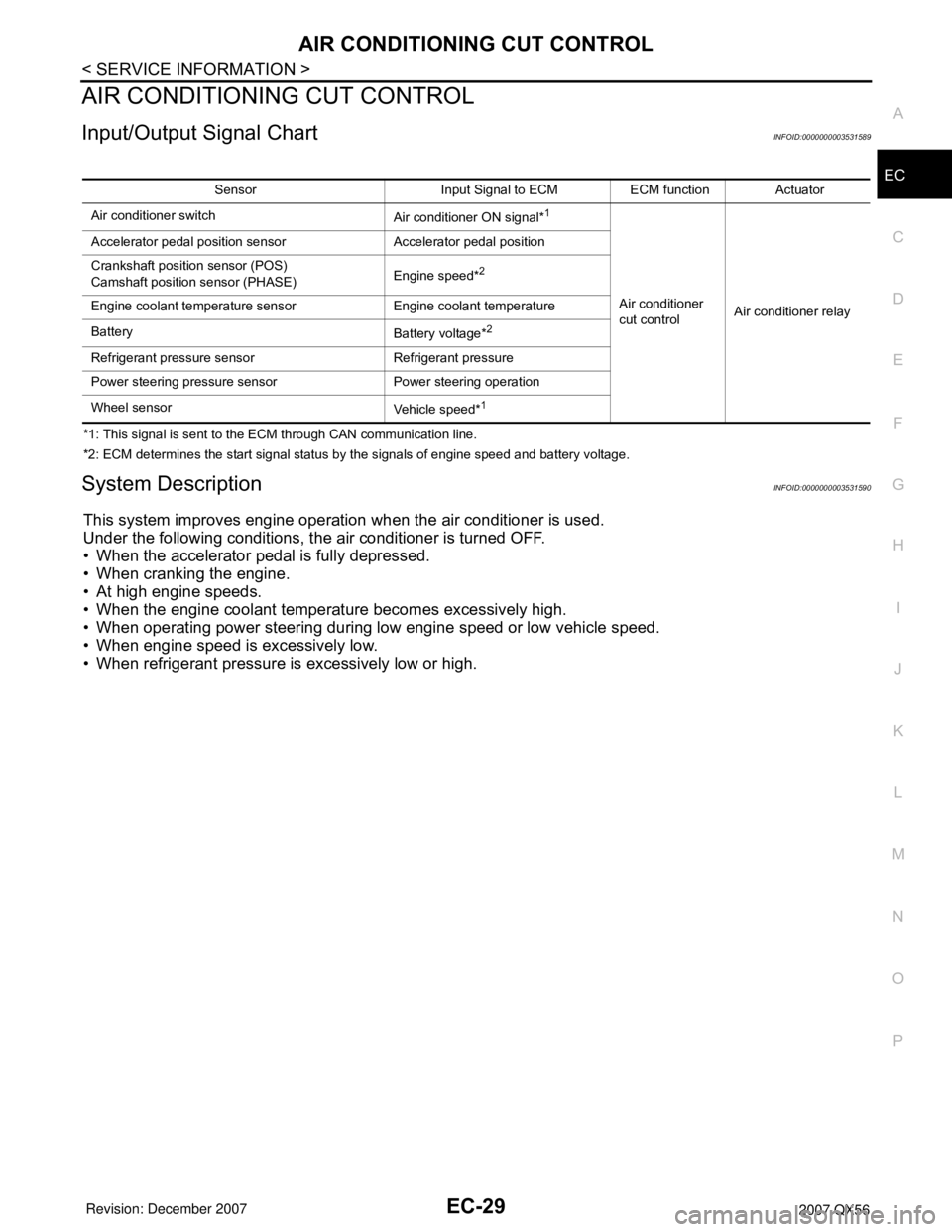
Input/Output Signal ChartINFOID:0000000003531589
*1: This signal is sent to the ECM through CAN communication line.
*2: ECM determines the start signal status by the signals of engine speed and battery voltage.
System DescriptionINFOID:0000000003531590
This system improves engine operation when the air conditioner is used.
Under the following conditions, the air conditioner is turned OFF.
• When the accelerator pedal is fully depressed.
• When cranking the engine.
• At high engine speeds.
• When the engine coolant temperature becomes excessively high.
• When operating power steering during low engine speed or low vehicle speed.
• When engine speed is excessively low.
• When refrigerant pressure is excessively low or high.
Sensor Input Signal to ECM ECM function Actuator
Air conditioner switch
Air conditioner ON signal*
1
Air conditioner
cut controlAir conditioner relay Accelerator pedal position sensor Accelerator pedal position
Crankshaft position sensor (POS)
Camshaft position sensor (PHASE)Engine speed*
2
Engine coolant temperature sensor Engine coolant temperature
Battery
Battery voltage*
2
Refrigerant pressure sensor Refrigerant pressure
Power steering pressure sensor Power steering operation
Wheel sensor
Vehicle speed*
1