2007 INFINITI QX56 relay
[x] Cancel search: relayPage 2602 of 3061
RSU-12
< SERVICE INFORMATION >
TROUBLE DIAGNOSIS
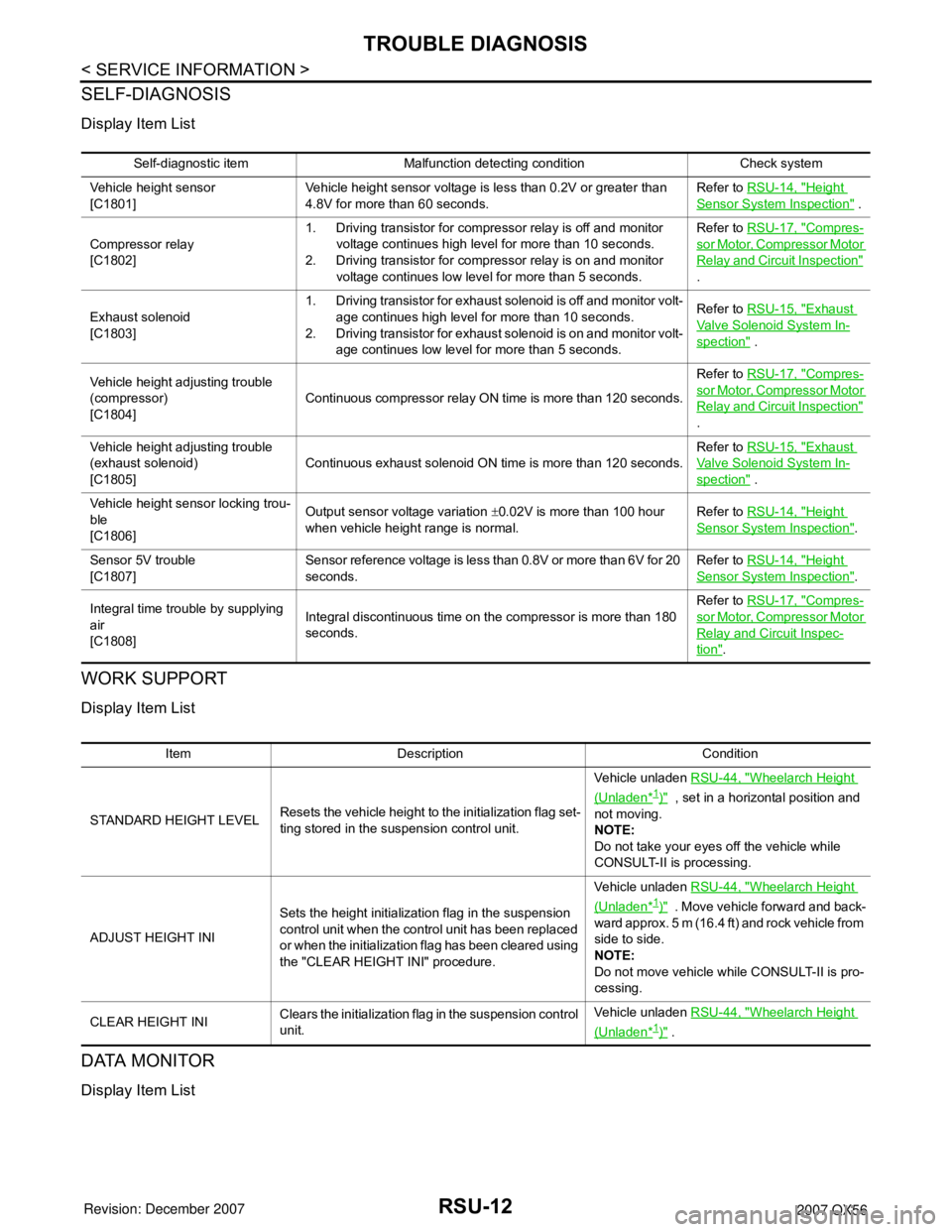
SELF-DIAGNOSIS
Display Item List
WORK SUPPORT
Display Item List
DATA MONITOR
Display Item List
Self-diagnostic item Malfunction detecting condition Check system
Vehicle height sensor
[C1801]Vehicle height sensor voltage is less than 0.2V or greater than
4.8V for more than 60 seconds.Refer to RSU-14, "
Height
Sensor System Inspection" .
Compressor relay
[C1802]1. Driving transistor for compressor relay is off and monitor
voltage continues high level for more than 10 seconds.
2. Driving transistor for compressor relay is on and monitor
voltage continues low level for more than 5 seconds.Refer to RSU-17, "
Compres-
sor Motor, Compressor Motor
Relay and Circuit Inspection"
.
Exhaust solenoid
[C1803]1. Driving transistor for exhaust solenoid is off and monitor volt-
age continues high level for more than 10 seconds.
2. Driving transistor for exhaust solenoid is on and monitor volt-
age continues low level for more than 5 seconds.Refer to RSU-15, "
Exhaust
Valve Solenoid System In-
spection" .
Vehicle height adjusting trouble
(compressor)
[C1804]Continuous compressor relay ON time is more than 120 seconds.Refer to RSU-17, "
Compres-
sor Motor, Compressor Motor
Relay and Circuit Inspection"
.
Vehicle height adjusting trouble
(exhaust solenoid)
[C1805]Continuous exhaust solenoid ON time is more than 120 seconds.Refer to RSU-15, "
Exhaust
Valve Solenoid System In-
spection" .
Vehicle height sensor locking trou-
ble
[C1806]Output sensor voltage variation ±0.02V is more than 100 hour
when vehicle height range is normal.Refer to RSU-14, "
Height
Sensor System Inspection".
Sensor 5V trouble
[C1807]Sensor reference voltage is less than 0.8V or more than 6V for 20
seconds.Refer to RSU-14, "
Height
Sensor System Inspection".
Integral time trouble by supplying
air
[C1808]Integral discontinuous time on the compressor is more than 180
seconds.Refer to RSU-17, "
Compres-
sor Motor, Compressor Motor
Relay and Circuit Inspec-
tion".
Item Description Condition
STANDARD HEIGHT LEVELResets the vehicle height to the initialization flag set-
ting stored in the suspension control unit.Vehicle unladen RSU-44, "
Wheelarch Height
(Unladen*1)" , set in a horizontal position and
not moving.
NOTE:
Do not take your eyes off the vehicle while
CONSULT-II is processing.
ADJUST HEIGHT INISets the height initialization flag in the suspension
control unit when the control unit has been replaced
or when the initialization flag has been cleared using
the "CLEAR HEIGHT INI" procedure.Vehicle unladen RSU-44, "
Wheelarch Height
(Unladen*1)" . Move vehicle forward and back-
ward approx. 5 m (16.4 ft) and rock vehicle from
side to side.
NOTE:
Do not move vehicle while CONSULT-II is pro-
cessing.
CLEAR HEIGHT INIClears the initialization flag in the suspension control
unit.Vehicle unladen RSU-44, "
Wheelarch Height
(Unladen*1)" .
Page 2607 of 3061
TROUBLE DIAGNOSIS FOR SELF-DIAGNOSTIC ITEMS
RSU-17
< SERVICE INFORMATION >
C
D
F
G
H
I
J
K
L
MA
B
RSU
N
O
P
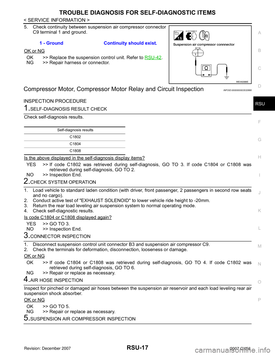
5. Check continuity between suspension air compressor connector
C9 terminal 1 and ground.
OK or NG
OK >> Replace the suspension control unit. Refer to RSU-42.
NG >> Repair harness or connector.
Compressor Motor, Compressor Motor Relay and Circuit InspectionINFOID:0000000003532666
INSPECTION PROCEDURE
1.SELF-DIAGNOSIS RESULT CHECK
Check self-diagnosis results.
Is the above displayed in the self-diagnosis display items?
YES >> If code C1802 was retrieved during self-diagnosis, GO TO 3. If code C1804 or C1808 was
retrieved during self-diagnosis, GO TO 2.
NO >> Inspection End.
2.CHECK SYSTEM OPERATION
1. Load vehicle to standard laden condition (with driver, front passenger, 2 passengers in second row seats
and no cargo).
2. Conduct active test of "EXHAUST SOLENOID" to lower vehicle ride height to -20mm.
3. Return the rear load leveling air suspension system to normal operating mode.
4. Check self-diagnostic results.
Is code C1804 or C1808 displayed again?
YES >> GO TO 3.
NO >> Inspection End.
3.CONNECTOR INSPECTION
1. Disconnect suspension control unit connector B3 and suspension air compressor C9.
2. Check the terminals for deformation, disconnection, looseness or damage.
OK or NG
OK >> If code C1804 or C1808 was retrieved during self-diagnosis, GO TO 4. If code C1802 was
retrieved during self-diagnosis, GO TO 6.
NG >> Repair or replace as necessary.
4.AIR HOSE INSPECTION
Inspect for pinched or damaged air hoses between the suspension air reservoir and each load leveling rear air
suspension shock absorber.
OK or NG
OK >> GO TO 5.
NG >> Repair or replace as necessary.
5.SUSPENSION AIR COMPRESSOR INSPECTION1 - Ground Continuity should exist.
WEIA0089E
Self-diagnosis results
C1802
C1804
C1808
Page 2609 of 3061
TROUBLE DIAGNOSES FOR SYMPTOMS
RSU-19
< SERVICE INFORMATION >
C
D
F
G
H
I
J
K
L
MA
B
RSU
N
O
P
TROUBLE DIAGNOSES FOR SYMPTOMS
Load Leveling Rear Air Suspension System Does Not OperateINFOID:0000000003532667
1.CHECK WARNING LAMP ACTIVATION
Make sure warning lamp remains off while driving.
OK or NG
OK >> GO TO 2.
NG >> Carry out self-diagnosis. Refer to RSU-11, "
CONSULT-II Function (AIR LEVELIZER)" .
2.CHECK FUSES AND FUSIBLE LINK
Check that the following fuses and fusible link are not blown.
OK or NG
OK >> GO TO 3.
NG >> If fuse or fusible link is blown, be sure to eliminate cause of malfunction before installing new fuse
or fusible link.
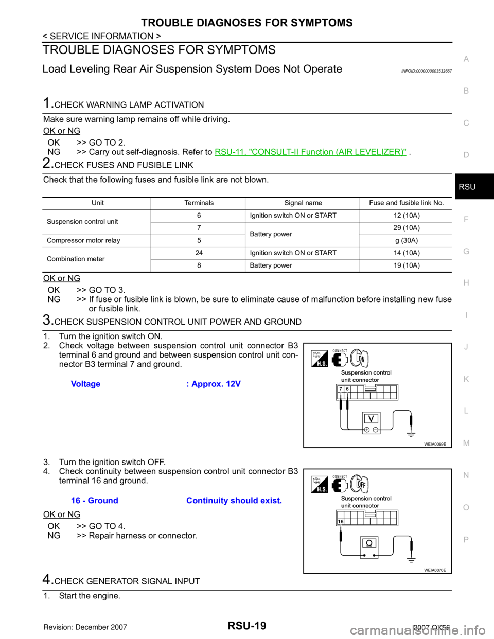
3.CHECK SUSPENSION CONTROL UNIT POWER AND GROUND
1. Turn the ignition switch ON.
2. Check voltage between suspension control unit connector B3
terminal 6 and ground and between suspension control unit con-
nector B3 terminal 7 and ground.
3. Turn the ignition switch OFF.
4. Check continuity between suspension control unit connector B3
terminal 16 and ground.
OK or NG
OK >> GO TO 4.
NG >> Repair harness or connector.
4.CHECK GENERATOR SIGNAL INPUT
1. Start the engine.
Unit Terminals Signal name Fuse and fusible link No.
Suspension control unit6 Ignition switch ON or START 12 (10A)
7
Battery power29 (10A)
Compressor motor relay 5 g (30A)
Combination meter24 Ignition switch ON or START 14 (10A)
8 Battery power 19 (10A)
Voltage : Approx. 12V
WEIA0069E
16 - Ground Continuity should exist.
WEIA0070E
Page 2657 of 3061

STARTING SYSTEM
SC-9
< SERVICE INFORMATION >
C
D
E
F
G
H
I
J
L
MA
B
SC
N
O
P
STARTING SYSTEM
System DescriptionINFOID:0000000003533319
Power is supplied at all times
• through 40A fusible link (letter m , located in the fuse and fusible link box)
• to ignition switch terminal B.
With the ignition switch in the START position, power is supplied
• from ignition switch terminal ST
• to IPDM E/R terminal 21.
With the ignition switch in the ON or START position, power is supplied to IPDM E/R (intelligent power distribu-
tion module engine room) CPU.
With the selector lever in the P or N position, power is supplied
• through A/T assembly terminal 9
• to IPDM E/R terminal 48.
Ground is supplied at all times
• to IPDM E/R terminals 38 and 59
• through body grounds E9, E15 and E24.
Then the starter relay is turned on.
The IPDM E/R is energized and power is supplied
• from terminal 19 of the IPDM E/R
• to terminal 1 of the starter motor windings.
The starter motor plunger closes and provides a closed circuit between the battery and the starter motor. The
starter motor is grounded to the cylinder block. With power and ground supplied, the starter motor operates.
Page 2662 of 3061
![INFINITI QX56 2007 Factory Service Manual SC-14
< SERVICE INFORMATION >
STARTING SYSTEM
• Starter relay [within the intelligent power distribution module engine room (IPDM E/R)]
• Harness for open or short
2.CHECK VOLTAGE DROP ON MAGNETIC INFINITI QX56 2007 Factory Service Manual SC-14
< SERVICE INFORMATION >
STARTING SYSTEM
• Starter relay [within the intelligent power distribution module engine room (IPDM E/R)]
• Harness for open or short
2.CHECK VOLTAGE DROP ON MAGNETIC](/manual-img/42/57029/w960_57029-2661.png)
SC-14
< SERVICE INFORMATION >
STARTING SYSTEM
• Starter relay [within the intelligent power distribution module engine room (IPDM E/R)]
• Harness for open or short
2.CHECK VOLTAGE DROP ON MAGNETIC SWITCH CIRCUIT
1. Turn the ignition switch OFF.
2. Connect starter motor connector F28.
3. Check voltage between starter motor connector F28 terminal 1
and battery positive terminal using a digital circuit tester.
OK or NG
OK >> Magnetic switch circuit is OK. Further inspection is nec-
essary. Refer to "WORK FLOW" .
NG >> Check harness between the battery and the magnetic
switch for poor continuity.
MINIMUM SPECIFICATION OF CRANKING VOLTAGE REFERENCING COOLANT TEMPERA-
TURE
Removal and InstallationINFOID:0000000003533322
REMOVAL
1. Remove the intake manifold. Refer to EM-17, "Removal and Installation".
2. Remove/disconnect the starter harness connectors.
3. Remove the two starter bolts, using power tools.
4. Remove the starter.
INSTALLATION
Installation is in the reverse order of removal.
CAUTION:
Tighten terminal nut carefully.Ignition switch in
START.: Less than 1V
WKIA1792E
Engine coolant temperature Voltage V
−30°C to −20°C (−22°F to −4°F) 8.4
−19°C to −10°C (−2°F to 14°F) 8.9
−9°C to 0°C (16°F to 32°F) 9.3
More than 1°C (More than 34°F) 9.7
WKIA1388E
Terminal nut : 10.8 N·m (1.1 kg-m, 8 ft-lb)
Page 2838 of 3061
TF-16
< SERVICE INFORMATION >
ALL-MODE 4WD SYSTEM
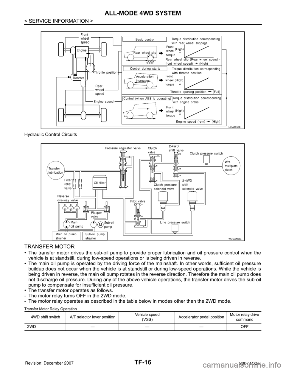
Hydraulic Control Circuits
TRANSFER MOTOR
• The transfer motor drives the sub-oil pump to provide proper lubrication and oil pressure control when the
vehicle is at standstill, during low-speed operations or is being driven in reverse.
• The main oil pump is operated by the driving force of the mainshaft. In other words, sufficient oil pressure
buildup does not occur when the vehicle is at standstill or during low-speed operations. While the vehicle is
being driven in reverse, the main oil pump rotates in the reverse direction. Therefore the main oil pump does
not discharge oil pressure. During any of the above vehicle operations, the transfer motor drives the sub-oil
pump to compensate for insufficient oil pressure.
• The transfer motor operates as follows.
- The motor relay turns OFF in the 2WD mode.
- The motor relay operates as described in the table below in modes other than the 2WD mode.
Transfer Motor Relay Operation
LDIA0055E
WDIA0163E
4WD shift switch A/T selector lever positionVehicle speed
(VSS)Accelerator pedal positionMotor relay drive
command
2WD — — — OFF
Page 2839 of 3061

ALL-MODE 4WD SYSTEM
TF-17
< SERVICE INFORMATION >
C
E
F
G
H
I
J
K
L
MA
B
TF
N
O
P
*: After 2.5 seconds have elapsed.
• 4WD shift switch, PNP switch, Neutral-4LO switch, vehicle speed sensor and throttle position sensor are
used in conjunction with the transfer motor.
WAIT DETECTION SWITCH
• The wait detection switch operates when there is “circulating” torque produced in the propeller shaft (L→H)
or when there is a phase difference between 2-4 sleeve and clutch drum (H→L). After the release of the “cir-
culating” torque, the wait detection switch helps provide the 4WD lock gear (clutch drum) shifts. A difference
may occur between the operation of the 4WD shift switch and actual drive mode. At this point, the wait
detection switch senses an actual drive mode.
• The wait detection switch operates as follows.
- 4WD lock gear (clutch drum) locked: ON
- 4WD lock gear (clutch drum) released: OFF
• The wait detection switch senses an actual drive mode and the 4WD shift indicator lamp indicates the vehi-
cle drive mode.
NEUTRAL-4LO SWITCH
The neutral-4LO switch detects that transfer gear is in neutral or 4LO (or shifting from neutral to 4LO) condi-
tion by L-H shift fork position.
AT P S W I T C H
ATP switch detects if transfer gear is in a neutral condition by L-H shift fork position.
NOTE:
Transfer gear may be in a neutral condition in 4H-4LO.
2-4WD SHIFT SOLENOID VALVE
The 2-4WD shift solenoid valve operates to apply oil pressure to the wet-multiplate clutch, depending on the
drive mode. The driving force is transmitted to the front wheels through the clutch so the vehicle is set in the
4WD mode. Setting the vehicle in the 2WD mode requires no pressure buildup. In other words, pressure force
applied to the wet-multiplate clutch becomes zero.
CLUTCH PRESSURE SOLENOID VALVE
The clutch pressure solenoid valve distributes torque (front and rear) in AUTO mode.
4H (LOCK) and 4LO“N” position 0 — ON
“P” position 00 - 0.07/8 OFF*
0.07/8 - 1/8 HOLD
1/8 - MAX ON
Other than “R” position0 < VSS ≤ 50 km/h (31 MPH)
— ON
50 km/h (31 MPH) < VSS < 55
km/h (34 MPH) HOLD
55 km/h (34 MPH) ≤ VSS OFF
“R” position — — ON
“R” position — — ON
AUTO“P” or “N” position00 - 0.07/8 OFF*
0.07/8 - 1/8 HOLD
1/8 - MAX ON
0 < VSS ≤ 50 km/h (31 MPH)
— ON
50 km/h (31 MPH) < VSS < 55
km/h (34 MPH) HOLD
55 km/h (34 MPH) ≤ VSS OFF
Other than “R”, "P" and "N"
position0 < VSS ≤ 50 km/h (31 MPH)
— ON
50 km/h (31 MPH) < VSS < 55
km/h (34 MPH) HOLD
55 km/h (34 MPH) ≤ VSS OFF 4WD shift switch A/T selector lever positionVehicle speed
(VSS)Accelerator pedal positionMotor relay drive
command
Page 2856 of 3061
TF-34
< SERVICE INFORMATION >
TROUBLE DIAGNOSIS
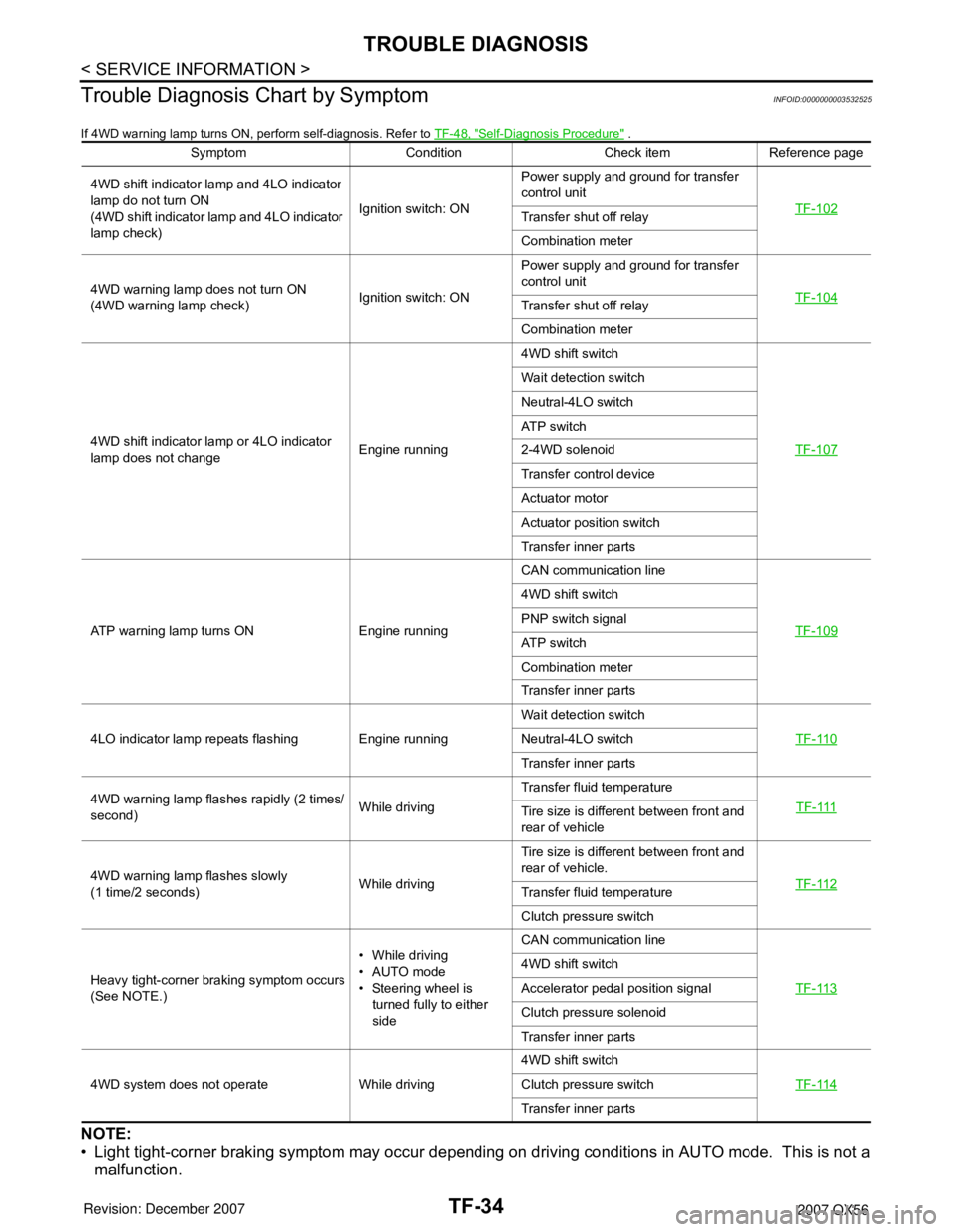
Trouble Diagnosis Chart by Symptom
INFOID:0000000003532525
If 4WD warning lamp turns ON, perform self-diagnosis. Refer to TF-48, "Self-Diagnosis Procedure" .
NOTE:
• Light tight-corner braking symptom may occur depending on driving conditions in AUTO mode. This is not a
malfunction.
Symptom Condition Check item Reference page
4WD shift indicator lamp and 4LO indicator
lamp do not turn ON
(4WD shift indicator lamp and 4LO indicator
lamp check)Ignition switch: ONPower supply and ground for transfer
control unit
TF-102
Transfer shut off relay
Combination meter
4WD warning lamp does not turn ON
(4WD warning lamp check)Ignition switch: ONPower supply and ground for transfer
control unit
TF-104
Transfer shut off relay
Combination meter
4WD shift indicator lamp or 4LO indicator
lamp does not changeEngine running4WD shift switch
TF-107
Wait detection switch
Neutral-4LO switch
ATP switch
2-4WD solenoid
Transfer control device
Actuator motor
Actuator position switch
Transfer inner parts
ATP warning lamp turns ON Engine runningCAN communication line
TF-109
4WD shift switch
PNP switch signal
ATP switch
Combination meter
Transfer inner parts
4LO indicator lamp repeats flashing Engine runningWait detection switch
TF-110
Neutral-4LO switch
Transfer inner parts
4WD warning lamp flashes rapidly (2 times/
second)While drivingTransfer fluid temperature
TF-111
Tire size is different between front and
rear of vehicle
4WD warning lamp flashes slowly
(1 time/2 seconds)While drivingTire size is different between front and
rear of vehicle.
TF-112
Transfer fluid temperature
Clutch pressure switch
Heavy tight-corner braking symptom occurs
(See NOTE.)• While driving
•AUTO mode
• Steering wheel is
turned fully to either
sideCAN communication line
TF-113
4WD shift switch
Accelerator pedal position signal
Clutch pressure solenoid
Transfer inner parts
4WD system does not operate While driving4WD shift switch
TF-114
Clutch pressure switch
Transfer inner parts