2007 INFINITI QX56 seats
[x] Cancel search: seatsPage 1842 of 3061
EM-72
< SERVICE INFORMATION >
CYLINDER HEAD
VALVE SEAT CONTACT
• After confirming that the dimensions of the valve guides and valves
are within specifications, perform this procedure.
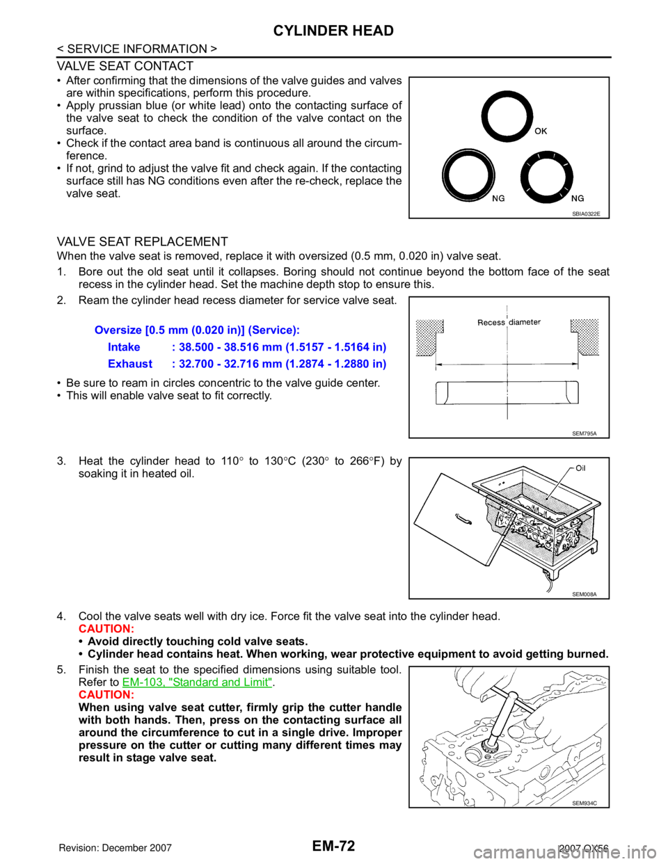
• Apply prussian blue (or white lead) onto the contacting surface of
the valve seat to check the condition of the valve contact on the
surface.
• Check if the contact area band is continuous all around the circum-
ference.
• If not, grind to adjust the valve fit and check again. If the contacting
surface still has NG conditions even after the re-check, replace the
valve seat.
VALVE SEAT REPLACEMENT
When the valve seat is removed, replace it with oversized (0.5 mm, 0.020 in) valve seat.
1. Bore out the old seat until it collapses. Boring should not continue beyond the bottom face of the seat
recess in the cylinder head. Set the machine depth stop to ensure this.
2. Ream the cylinder head recess diameter for service valve seat.
• Be sure to ream in circles concentric to the valve guide center.
• This will enable valve seat to fit correctly.
3. Heat the cylinder head to 110° to 130°C (230° to 266°F) by
soaking it in heated oil.
4. Cool the valve seats well with dry ice. Force fit the valve seat into the cylinder head.
CAUTION:
• Avoid directly touching cold valve seats.
• Cylinder head contains heat. When working, wear protective equipment to avoid getting burned.
5. Finish the seat to the specified dimensions using suitable tool.
Refer to EM-103, "
Standard and Limit".
CAUTION:
When using valve seat cutter, firmly grip the cutter handle
with both hands. Then, press on the contacting surface all
around the circumference to cut in a single drive. Improper
pressure on the cutter or cutting many different times may
result in stage valve seat.
SBIA0322E
Oversize [0.5 mm (0.020 in)] (Service):
Intake : 38.500 - 38.516 mm (1.5157 - 1.5164 in)
Exhaust : 32.700 - 32.716 mm (1.2874 - 1.2880 in)
SEM795A
SEM008A
SEM934C
Page 1855 of 3061
CYLINDER BLOCK
EM-85
< SERVICE INFORMATION >
C
D
E
F
G
H
I
J
K
L
MA
EM
N
P O
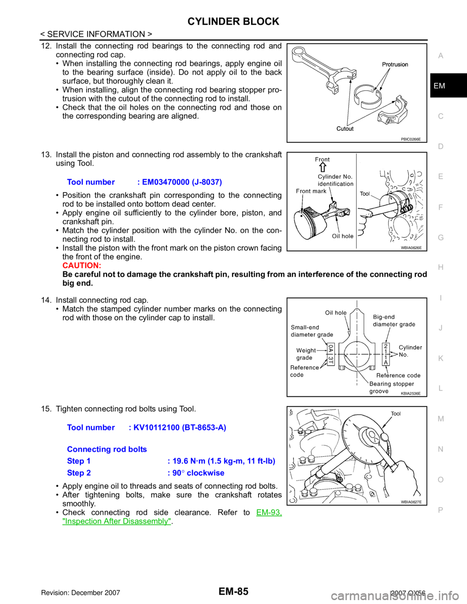
12. Install the connecting rod bearings to the connecting rod and
connecting rod cap.
• When installing the connecting rod bearings, apply engine oil
to the bearing surface (inside). Do not apply oil to the back
surface, but thoroughly clean it.
• When installing, align the connecting rod bearing stopper pro-
trusion with the cutout of the connecting rod to install.
• Check that the oil holes on the connecting rod and those on
the corresponding bearing are aligned.
13. Install the piston and connecting rod assembly to the crankshaft
using Tool.
• Position the crankshaft pin corresponding to the connecting
rod to be installed onto bottom dead center.
• Apply engine oil sufficiently to the cylinder bore, piston, and
crankshaft pin.
• Match the cylinder position with the cylinder No. on the con-
necting rod to install.
• Install the piston with the front mark on the piston crown facing
the front of the engine.
CAUTION:
Be careful not to damage the crankshaft pin, resulting from an interference of the connecting rod
big end.
14. Install connecting rod cap.
• Match the stamped cylinder number marks on the connecting
rod with those on the cylinder cap to install.
15. Tighten connecting rod bolts using Tool.
• Apply engine oil to threads and seats of connecting rod bolts.
• After tightening bolts, make sure the crankshaft rotates
smoothly.
• Check connecting rod side clearance. Refer to EM-93,
"Inspection After Disassembly".
PBIC0266E
Tool number : EM03470000 (J-8037)
WBIA0626E
KBIA2536E
Tool number : KV10112100 (BT-8653-A)
Connecting rod bolts
Step 1 : 19.6 N·m (1.5 kg-m, 11 ft-lb)
Step 2 : 90° clockwise
WBIA0627E
Page 2027 of 3061

GW-8
< SERVICE INFORMATION >
SQUEAK AND RATTLE TROUBLE DIAGNOSIS
Most of these incidents can be repaired by adjusting, securing or insulating the item(s) or component(s) caus-
ing the noise.
SUNROOF/HEADLINER
Noises in the sunroof/headliner area can often be traced to one of the following:
1. Sunroof lid, rail, linkage or seals making a rattle or light knocking noise
2. Sun visor shaft shaking in the holder
3. Front or rear windshield touching headliner and squeaking
Again, pressing on the components to stop the noise while duplicating the conditions can isolate most of these
incidents. Repairs usually consist of insulating with felt cloth tape.
OVERHEAD CONSOLE (FRONT AND REAR)
Overhead console noises are often caused by the console panel clips not being engaged correctly. Most of
these incidents are repaired by pushing up on the console at the clip locations until the clips engage.
In addition look for:
1. Loose harness or harness connectors.
2. Front console map/reading lamp lense loose.
3. Loose screws at console attachment points.
SEATS
When isolating seat noise it's important to note the position the seat is in and the load placed on the seat when
the noise is present. These conditions should be duplicated when verifying and isolating the cause of the
noise.
Cause of seat noise include:
1. Headrest rods and holder
2. A squeak between the seat pad cushion and frame
3. The rear seatback lock and bracket
These noises can be isolated by moving or pressing on the suspected components while duplicating the con-
ditions under which the noise occurs. Most of these incidents can be repaired by repositioning the component
or applying urethane tape to the contact area.
UNDERHOOD
Some interior noise may be caused by components under the hood or on the engine wall. The noise is then
transmitted into the passenger compartment.
Causes of transmitted underhood noise include:
1. Any component mounted to the engine wall
2. Components that pass through the engine wall
3. Engine wall mounts and connectors
4. Loose radiator mounting pins
5. Hood bumpers out of adjustment
6. Hood striker out of adjustment
These noises can be difficult to isolate since they cannot be reached from the interior of the vehicle. The best
method is to secure, move or insulate one component at a time and test drive the vehicle. Also, engine RPM
or load can be changed to isolate the noise. Repairs can usually be made by moving, adjusting, securing, or
insulating the component causing the noise.
Page 2119 of 3061
SQUEAK AND RATTLE TROUBLE DIAGNOSIS
IP-7
< SERVICE INFORMATION >
C
D
E
F
G
H
J
K
L
MA
B
IP
N
O
P
Most of these incidents can be repaired by adjusting, securing or insulating the item(s) or component(s) caus-
ing the noise.
SUNROOF/HEADLINING
Noises in the sunroof/headlining area can often be traced to one of the following:
1. Sunroof lid, rail, linkage or seals making a rattle or light knocking noise
2. Sun visor shaft shaking in the holder
3. Front or rear windshield touching headliner and squeaking
Again, pressing on the components to stop the noise while duplicating the conditions can isolate most of these
incidents. Repairs usually consist of insulating with felt cloth tape.
OVERHEAD CONSOLE (FRONT AND REAR)
Overhead console noises are often caused by the console panel clips not being engaged correctly. Most of
these incidents are repaired by pushing up on the console at the clip locations until the clips engage.
In addition look for:
1. Loose harness or harness connectors.
2. Front console map/reading lamp lens loose.
3. Loose screws at console attachment points.
SEATS
When isolating seat noise it's important to note the position the seat is in and the load placed on the seat when
the noise is present. These conditions should be duplicated when verifying and isolating the cause of the
noise.
Cause of seat noise include:
1. Headrest rods and holder
2. A squeak between the seat pad cushion and frame
3. The rearseat back lock and bracket
These noises can be isolated by moving or pressing on the suspected components while duplicating the con-
ditions under which the noise occurs. Most of these incidents can be repaired by repositioning the component
or applying urethane tape to the contact area.
UNDERHOOD
Some interior noise may be caused by components under the hood or on the engine wall. The noise is then
transmitted into the passenger compartment.
Causes of transmitted underhood noise include:
1. Any component mounted to the engine wall
2. Components that pass through the engine wall
3. Engine wall mounts and connectors
4. Loose radiator mounting pins
5. Hood bumpers out of adjustment
6. Hood striker out of adjustment
These noises can be difficult to isolate since they cannot be reached from the interior of the vehicle. The best
method is to secure, move or insulate one component at a time and test drive the vehicle. Also, engine RPM
or load can be changed to isolate the noise. Repairs can usually be made by moving, adjusting, securing, or
insulating the component causing the noise.
Page 2126 of 3061
IP-14
< SERVICE INFORMATION >
INSTRUMENT PANEL ASSEMBLY
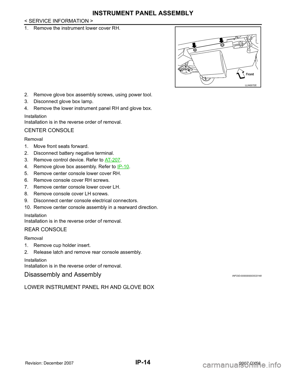
1. Remove the instrument lower cover RH.
2. Remove glove box assembly screws, using power tool.
3. Disconnect glove box lamp.
4. Remove the lower instrument panel RH and glove box.
Installation
Installation is in the reverse order of removal.
CENTER CONSOLE
Removal
1. Move front seats forward.
2. Disconnect battery negative terminal.
3. Remove control device. Refer to AT-207
.
4. Remove glove box assembly. Refer to IP-10
.
5. Remove center console lower cover RH.
6. Remove console cover RH screws.
7. Remove center console lower cover LH.
8. Remove console cover LH screws.
9. Disconnect center console electrical connectors.
10. Remove center console assembly in a rearward direction.
Installation
Installation is in the reverse order of removal.
REAR CONSOLE
Removal
1. Remove cup holder insert.
2. Release latch and remove rear console assembly.
Installation
Installation is in the reverse order of removal.
Disassembly and AssemblyINFOID:0000000003533148
LOWER INSTRUMENT PANEL RH AND GLOVE BOX
LLIA0072E
Page 2366 of 3061
MA-4
< SERVICE INFORMATION >
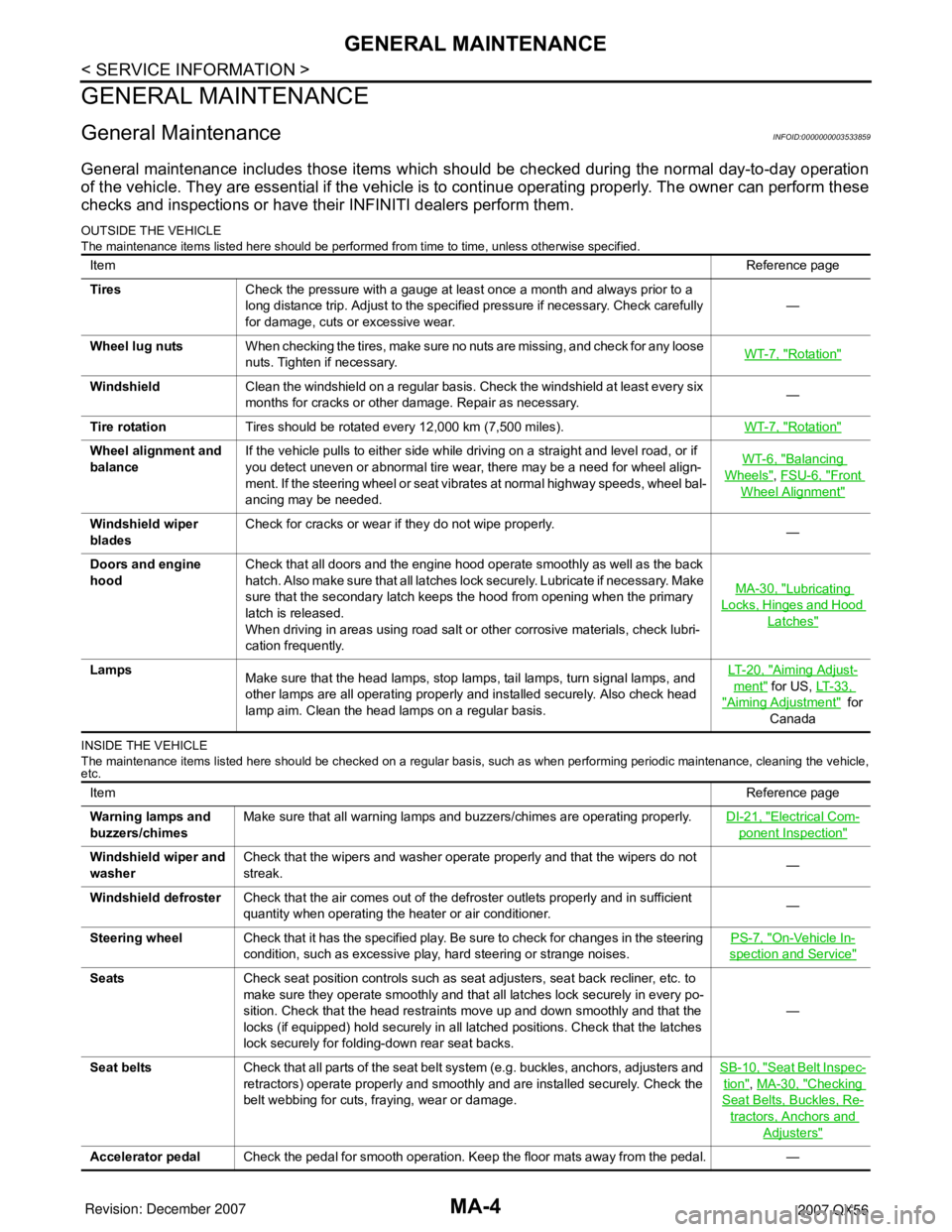
GENERAL MAINTENANCE
GENERAL MAINTENANCE
General MaintenanceINFOID:0000000003533859
General maintenance includes those items which should be checked during the normal day-to-day operation
of the vehicle. They are essential if the vehicle is to continue operating properly. The owner can perform these
checks and inspections or have their INFINITI dealers perform them.
OUTSIDE THE VEHICLE
The maintenance items listed here should be performed from time to time, unless otherwise specified.
INSIDE THE VEHICLE
The maintenance items listed here should be checked on a regular basis, such as when performing periodic maintenance, cleaning the vehicle,
etc.
ItemReference page
TiresCheck the pressure with a gauge at least once a month and always prior to a
long distance trip. Adjust to the specified pressure if necessary. Check carefully
for damage, cuts or excessive wear.—
Wheel lug nutsWhen checking the tires, make sure no nuts are missing, and check for any loose
nuts. Tighten if necessary.WT-7, "
Rotation"
WindshieldClean the windshield on a regular basis. Check the windshield at least every six
months for cracks or other damage. Repair as necessary.—
Tire rotationTires should be rotated every 12,000 km (7,500 miles).WT-7, "
Rotation"
Wheel alignment and
balanceIf the vehicle pulls to either side while driving on a straight and level road, or if
you detect uneven or abnormal tire wear, there may be a need for wheel align-
ment. If the steering wheel or seat vibrates at normal highway speeds, wheel bal-
ancing may be needed.WT-6, "Balancing
Wheels", FSU-6, "Front
Wheel Alignment"
Windshield wiper
bladesCheck for cracks or wear if they do not wipe properly.
—
Doors and engine
hoodCheck that all doors and the engine hood operate smoothly as well as the back
hatch. Also make sure that all latches lock securely. Lubricate if necessary. Make
sure that the secondary latch keeps the hood from opening when the primary
latch is released.
When driving in areas using road salt or other corrosive materials, check lubri-
cation frequently.MA-30, "
Lubricating
Locks, Hinges and Hood
Latches"
Lamps
Make sure that the head lamps, stop lamps, tail lamps, turn signal lamps, and
other lamps are all operating properly and installed securely. Also check head
lamp aim. Clean the head lamps on a regular basis.LT- 2 0 , "Aiming Adjust-
ment" for US, LT- 3 3 ,
"Aiming Adjustment" for
Canada
ItemReference page
Warning lamps and
buzzers/chimesMake sure that all warning lamps and buzzers/chimes are operating properly.DI-21, "
Electrical Com-
ponent Inspection"
Windshield wiper and
washerCheck that the wipers and washer operate properly and that the wipers do not
streak.—
Windshield defrosterCheck that the air comes out of the defroster outlets properly and in sufficient
quantity when operating the heater or air conditioner.—
Steering wheelCheck that it has the specified play. Be sure to check for changes in the steering
condition, such as excessive play, hard steering or strange noises.PS-7, "
On-Vehicle In-
spection and Service"
SeatsCheck seat position controls such as seat adjusters, seat back recliner, etc. to
make sure they operate smoothly and that all latches lock securely in every po-
sition. Check that the head restraints move up and down smoothly and that the
locks (if equipped) hold securely in all latched positions. Check that the latches
lock securely for folding-down rear seat backs.—
Seat beltsCheck that all parts of the seat belt system (e.g. buckles, anchors, adjusters and
retractors) operate properly and smoothly and are installed securely. Check the
belt webbing for cuts, fraying, wear or damage.SB-10, "
Seat Belt Inspec-
tion", MA-30, "Checking
Seat Belts, Buckles, Re-
tractors, Anchors and
Adjusters"
Accelerator pedalCheck the pedal for smooth operation. Keep the floor mats away from the pedal. —
Page 2539 of 3061
SQUEAK AND RATTLE TROUBLE DIAGNOSIS
RF-7
< SERVICE INFORMATION >
C
D
E
F
G
H
J
K
L
MA
B
RF
N
O
P
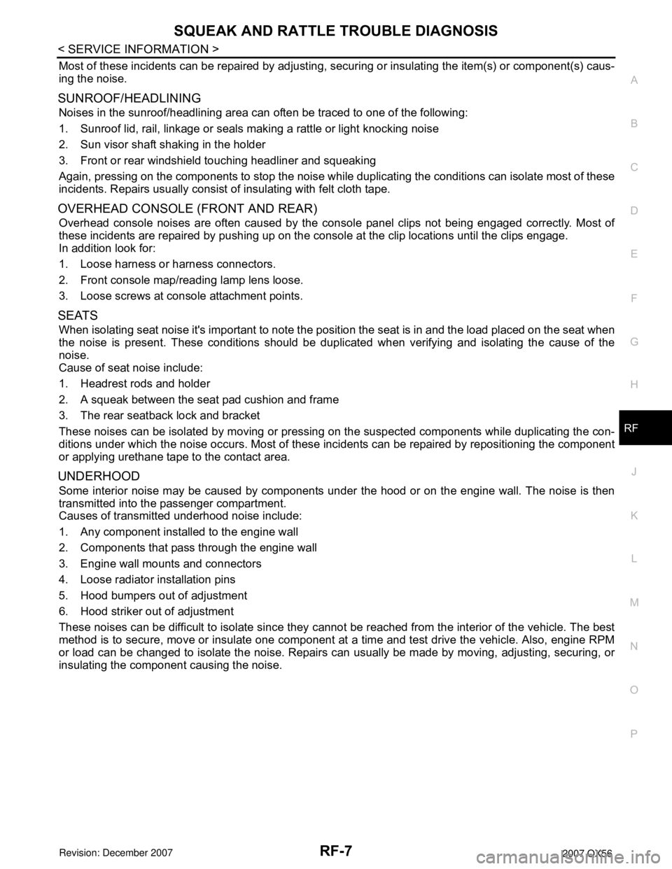
Most of these incidents can be repaired by adjusting, securing or insulating the item(s) or component(s) caus-
ing the noise.
SUNROOF/HEADLINING
Noises in the sunroof/headlining area can often be traced to one of the following:
1. Sunroof lid, rail, linkage or seals making a rattle or light knocking noise
2. Sun visor shaft shaking in the holder
3. Front or rear windshield touching headliner and squeaking
Again, pressing on the components to stop the noise while duplicating the conditions can isolate most of these
incidents. Repairs usually consist of insulating with felt cloth tape.
OVERHEAD CONSOLE (FRONT AND REAR)
Overhead console noises are often caused by the console panel clips not being engaged correctly. Most of
these incidents are repaired by pushing up on the console at the clip locations until the clips engage.
In addition look for:
1. Loose harness or harness connectors.
2. Front console map/reading lamp lens loose.
3. Loose screws at console attachment points.
SEATS
When isolating seat noise it's important to note the position the seat is in and the load placed on the seat when
the noise is present. These conditions should be duplicated when verifying and isolating the cause of the
noise.
Cause of seat noise include:
1. Headrest rods and holder
2. A squeak between the seat pad cushion and frame
3. The rear seatback lock and bracket
These noises can be isolated by moving or pressing on the suspected components while duplicating the con-
ditions under which the noise occurs. Most of these incidents can be repaired by repositioning the component
or applying urethane tape to the contact area.
UNDERHOOD
Some interior noise may be caused by components under the hood or on the engine wall. The noise is then
transmitted into the passenger compartment.
Causes of transmitted underhood noise include:
1. Any component installed to the engine wall
2. Components that pass through the engine wall
3. Engine wall mounts and connectors
4. Loose radiator installation pins
5. Hood bumpers out of adjustment
6. Hood striker out of adjustment
These noises can be difficult to isolate since they cannot be reached from the interior of the vehicle. The best
method is to secure, move or insulate one component at a time and test drive the vehicle. Also, engine RPM
or load can be changed to isolate the noise. Repairs can usually be made by moving, adjusting, securing, or
insulating the component causing the noise.
Page 2554 of 3061
RF-22
< SERVICE INFORMATION >
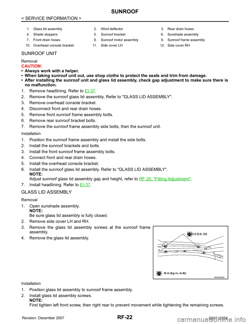
SUNROOF
SUNROOF UNIT
Removal
CAUTION:
• Always work with a helper.
• When taking sunroof unit out, use shop cloths to protect the seats and trim from damage.
• After installing the sunroof unit and glass lid assembly, check gap adjustment to make sure there is
no malfunction.
1. Remove headlining. Refer to EI-37
.
2. Remove the sunroof glass lid assembly. Refer to "GLASS LID ASSEMBLY".
3. Remove overhead console bracket.
4. Disconnect front and rear drain hoses.
5. Remove front sunroof frame assembly bolts.
6. Remove rear sunroof bracket bolts.
7. Remove the sunroof frame assembly side bolts, then the sunroof unit.
Installation
1. Position the sunroof frame assembly and install the side bolts.
2. Install the sunroof brackets and bolts.
3. Install the front sunroof frame assembly bolts.
4. Connect front and rear drain hoses.
5. Install the overhead console bracket.
6. Install the sunroof glass lid assembly. Refer to "GLASS LID ASSEMBLY".
NOTE:
Adjust sunroof glass lid assembly gap and height, refer to RF-20, "
Fitting Adjustment".
7. Install headlining. Refer to EI-37
.
GLASS LID ASSEMBLY
Removal
1. Open sunshade assembly.
NOTE:
Be sure glass lid assembly is fully closed.
2. Remove side cover LH and RH.
3. Remove the glass lid assembly screws at the sunroof frame
assembly.
4. Remove the glass lid assembly.
Installation
1. Position glass lid assembly to sunroof frame assembly.
2. Install glass lid assembly screws.
NOTE:
First tighten left front screw, then right rear to prevent movement while tightening the remaining screws.
1. Glass lid assembly 2. Wind deflector 3. Rear drain hoses
4. Shade stoppers 5. Sunroof bracket 6. Sunshade assembly
7. Front drain hoses 8. Sunroof motor assembly 9. Sunroof frame assembly
10. Overhead console bracket 11. Side cover LH 12. Side cover RH
WIIA0252E