2007 INFINITI QX56 height adjustment
[x] Cancel search: height adjustmentPage 1913 of 3061
FFD-14
< SERVICE INFORMATION >
FRONT FINAL DRIVE ASSEMBLY
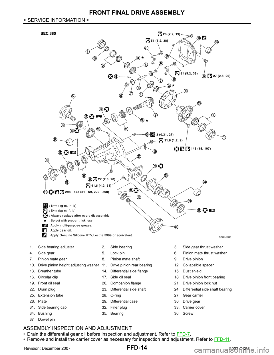
ASSEMBLY INSPECTION AND ADJUSTMENT
• Drain the differential gear oil before inspection and adjustment. Refer to FFD-7.
• Remove and install the carrier cover as necessary for inspection and adjustment. Refer to FFD-11
.
1. Side bearing adjuster 2. Side bearing 3. Side gear thrust washer
4. Side gear 5. Lock pin 6. Pinion mate thrust washer
7. Pinion mate gear 8. Pinion mate shaft 9. Drive pinion
10. Drive pinion height adjusting washer 11. Drive pinion rear bearing 12. Collapsible spacer
13. Breather tube 14. Differential side flange 15. Dust shield
16. Circular clip 17. Side oil seal 18. Drive pinion front bearing
19. Front oil seal 20. Companion flange 21. Drive pinion lock nut
22. Drain plug 23. Differential side shaft 24. Differential side shaft bearing
25. Extension tube 26. O-ring 27. Gear carrier
28. Plate 29. Differential case 30. Drive gear
31. Side bearing cap 32. Filler plug 33. Carrier cover
34. Bushing 35. Bearing 36 Screw
37 Dowel pin
SDIA3207E
Page 1915 of 3061
FFD-16
< SERVICE INFORMATION >
FRONT FINAL DRIVE ASSEMBLY
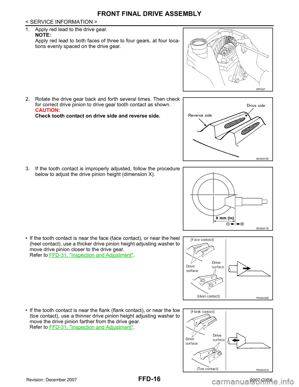
1. Apply red lead to the drive gear.
NOTE:
Apply red lead to both faces of three to four gears, at four loca-
tions evenly spaced on the drive gear.
2. Rotate the drive gear back and forth several times. Then check
for correct drive pinion to drive gear tooth contact as shown.
CAUTION:
Check tooth contact on drive side and reverse side.
3. If the tooth contact is improperly adjusted, follow the procedure
below to adjust the drive pinion height (dimension X).
• If the tooth contact is near the face (face contact), or near the heel
(heel contact), use a thicker drive pinion height adjusting washer to
move drive pinion closer to the drive gear.
Refer to FFD-31, "
Inspection and Adjustment".
• If the tooth contact is near the flank (flank contact), or near the toe
(toe contact), use a thinner drive pinion height adjusting washer to
move the drive pinion farther from the drive gear.
Refer to FFD-31, "
Inspection and Adjustment".
SPD357
SDIA0570E
SDIA0517E
PDIA0440E
PDIA0441E
Page 1923 of 3061
FFD-24
< SERVICE INFORMATION >
FRONT FINAL DRIVE ASSEMBLY
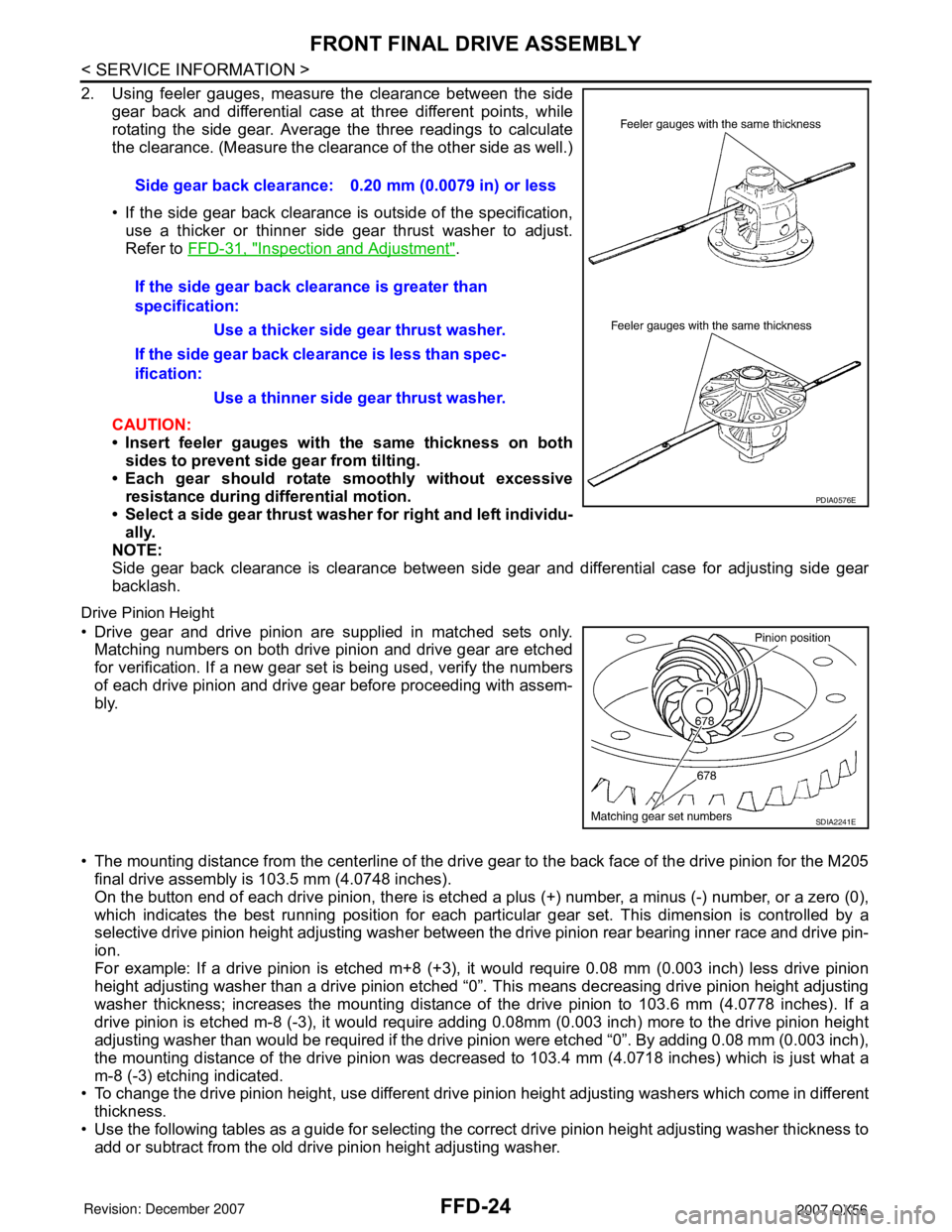
2. Using feeler gauges, measure the clearance between the side
gear back and differential case at three different points, while
rotating the side gear. Average the three readings to calculate
the clearance. (Measure the clearance of the other side as well.)
• If the side gear back clearance is outside of the specification,
use a thicker or thinner side gear thrust washer to adjust.
Refer to FFD-31, "
Inspection and Adjustment".
CAUTION:
• Insert feeler gauges with the same thickness on both
sides to prevent side gear from tilting.
• Each gear should rotate smoothly without excessive
resistance during differential motion.
• Select a side gear thrust washer for right and left individu-
ally.
NOTE:
Side gear back clearance is clearance between side gear and differential case for adjusting side gear
backlash.
Drive Pinion Height
• Drive gear and drive pinion are supplied in matched sets only.
Matching numbers on both drive pinion and drive gear are etched
for verification. If a new gear set is being used, verify the numbers
of each drive pinion and drive gear before proceeding with assem-
bly.
• The mounting distance from the centerline of the drive gear to the back face of the drive pinion for the M205
final drive assembly is 103.5 mm (4.0748 inches).
On the button end of each drive pinion, there is etched a plus (+) number, a minus (-) number, or a zero (0),
which indicates the best running position for each particular gear set. This dimension is controlled by a
selective drive pinion height adjusting washer between the drive pinion rear bearing inner race and drive pin-
ion.
For example: If a drive pinion is etched m+8 (+3), it would require 0.08 mm (0.003 inch) less drive pinion
height adjusting washer than a drive pinion etched “0”. This means decreasing drive pinion height adjusting
washer thickness; increases the mounting distance of the drive pinion to 103.6 mm (4.0778 inches). If a
drive pinion is etched m-8 (-3), it would require adding 0.08mm (0.003 inch) more to the drive pinion height
adjusting washer than would be required if the drive pinion were etched “0”. By adding 0.08 mm (0.003 inch),
the mounting distance of the drive pinion was decreased to 103.4 mm (4.0718 inches) which is just what a
m-8 (-3) etching indicated.
• To change the drive pinion height, use different drive pinion height adjusting washers which come in different
thickness.
• Use the following tables as a guide for selecting the correct drive pinion height adjusting washer thickness to
add or subtract from the old drive pinion height adjusting washer.Side gear back clearance: 0.20 mm (0.0079 in) or less
If the side gear back clearance is greater than
specification:
Use a thicker side gear thrust washer.
If the side gear back clearance is less than spec-
ification:
Use a thinner side gear thrust washer.
PDIA0576E
SDIA2241E
Page 1930 of 3061
SERVICE DATA AND SPECIFICATIONS (SDS)
FFD-31
< SERVICE INFORMATION >
C
E
F
G
H
I
J
K
L
MA
B
FFD
N
O
P
SERVICE DATA AND SPECIFICATIONS (SDS)
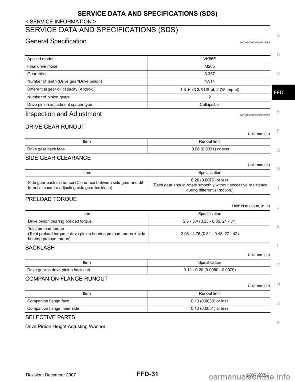
General SpecificationINFOID:0000000003532595
Inspection and AdjustmentINFOID:0000000003532596
DRIVE GEAR RUNOUT
Unit: mm (in)
SIDE GEAR CLEARANCE
Unit: mm (in)
PRELOAD TORQUE
Unit: N·m (kg-m, in-lb)
BACKLASH
Unit: mm (in)
COMPANION FLANGE RUNOUT
Unit: mm (in)
SELECTIVE PARTS
Drive Pinion Height Adjusting Washer
Applied modelVK56E
Final drive modelM205
Gear ratio3.357
Number of teeth (Drive gear/Drive pinion) 47/14
Differential gear oil capacity (Approx.)
1.6 (3 3/8 US pt, 2 7/8 Imp pt)
Number of pinion gears2
Drive pinion adjustment spacer type Collapsible
Item Runout limit
Drive gear back face 0.08 (0.0031) or less
Item Specification
Side gear back clearance (Clearance between side gear and dif-
ferential case for adjusting side gear backlash)0.20 (0.0079) or less
(Each gear should rotate smoothly without excessive resistance
during differential motion.)
Item Specification
Drive pinion bearing preload torque 2.3 - 3.4 (0.23 - 0.35, 21 - 31)
Total preload torque
(Total preload torque = drive pinion bearing preload torque + side
bearing preload torque).2.98 - 4.76 (0.31 - 0.48, 27 - 42)
Item Specification
Drive gear to drive pinion backlash 0.12 - 0.20 (0.0050 - 0.0079)
Item Runout limit
Companion flange face 0.10 (0.0039) or less
Companion flange inner side 0.13 (0.0051) or less
Page 1952 of 3061
FSU-6
< SERVICE INFORMATION >
ON-VEHICLE SERVICE
ON-VEHICLE SERVICE
Front Suspension PartsINFOID:0000000003532636
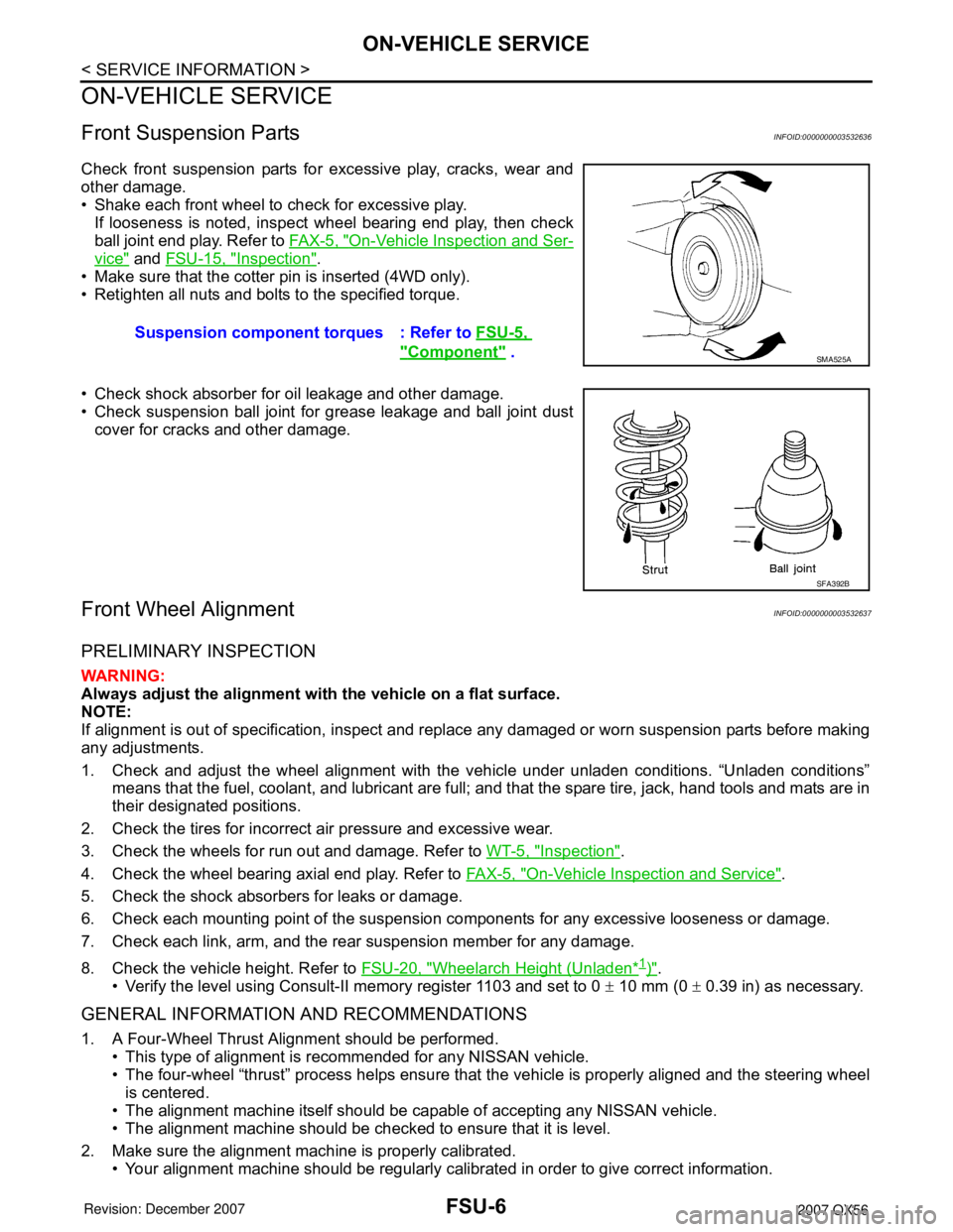
Check front suspension parts for excessive play, cracks, wear and
other damage.
• Shake each front wheel to check for excessive play.
If looseness is noted, inspect wheel bearing end play, then check
ball joint end play. Refer to FA X - 5 , "
On-Vehicle Inspection and Ser-
vice" and FSU-15, "Inspection".
• Make sure that the cotter pin is inserted (4WD only).
• Retighten all nuts and bolts to the specified torque.
• Check shock absorber for oil leakage and other damage.
• Check suspension ball joint for grease leakage and ball joint dust
cover for cracks and other damage.
Front Wheel AlignmentINFOID:0000000003532637
PRELIMINARY INSPECTION
WARNING:
Always adjust the alignment with the vehicle on a flat surface.
NOTE:
If alignment is out of specification, inspect and replace any damaged or worn suspension parts before making
any adjustments.
1. Check and adjust the wheel alignment with the vehicle under unladen conditions. “Unladen conditions”
means that the fuel, coolant, and lubricant are full; and that the spare tire, jack, hand tools and mats are in
their designated positions.
2. Check the tires for incorrect air pressure and excessive wear.
3. Check the wheels for run out and damage. Refer to WT-5, "
Inspection".
4. Check the wheel bearing axial end play. Refer to FA X - 5 , "
On-Vehicle Inspection and Service".
5. Check the shock absorbers for leaks or damage.
6. Check each mounting point of the suspension components for any excessive looseness or damage.
7. Check each link, arm, and the rear suspension member for any damage.
8. Check the vehicle height. Refer to FSU-20, "
Wheelarch Height (Unladen*1)".
• Verify the level using Consult-II memory register 1103 and set to 0 ± 10 mm (0 ± 0.39 in) as necessary.
GENERAL INFORMATION AND RECOMMENDATIONS
1. A Four-Wheel Thrust Alignment should be performed.
• This type of alignment is recommended for any NISSAN vehicle.
• The four-wheel “thrust” process helps ensure that the vehicle is properly aligned and the steering wheel
is centered.
• The alignment machine itself should be capable of accepting any NISSAN vehicle.
• The alignment machine should be checked to ensure that it is level.
2. Make sure the alignment machine is properly calibrated.
• Your alignment machine should be regularly calibrated in order to give correct information.Suspension component torques : Refer to FSU-5,
"Component" . SMA525A
SFA392B
Page 2109 of 3061
IDX-5
A
C
D
E
F
G
H
I
J
K
L B
IDX
ALPHABETICAL INDEX
Grease .............................................................. MA-11
Ground distribution ............................................ PG-31
H
H/AIM - Wiring diagram ...................................... LT-51
H/LAMP - Wiring diagram .................................... LT-9
Handling precautions for plastics ..................... BL-179
Harness connector ............................................ PG-68
Harness layout .................................................. PG-41
Hazard warning lamp ......................................... LT-63
Headlamp ............................................................. LT-5
Headlamp aiming control ................................... LT-51
Headlamp leveler - See Headlamp aiming control . LT-
51
Headlamp removal and installation .................... LT-25
Heated oxygen sensor 2 (bank 1) .... EC-276, EC-287,
EC-300
Heated oxygen sensor 2 (bank 2) .... EC-276, EC-287,
EC-300
Heated oxygen sensor 2 heater (bank 1) ........ EC-181
Heated oxygen sensor 2 heater (bank 2) ........ EC-181
Heated seat ....................................................... SE-82
Heater and cooling unit (Heater core) . ATC-157, ATC-
160
Heater unit (heater core) ............... ATC-157, ATC-160
Height (Dimensions) ........................................... GI-51
HFC134a (R134a) system identification ........... ATC-6
HFC134a (R134a) system precaution ............... ATC-5
HFC134a (R134a) system service procedure ATC-175
HFC134a (R134a) system service tools ......... ATC-14
HFC134a system service equipment precaution ATC-
11
High and low reverse clutch solenoid valve .... AT-147,
AT-149
Homelink universal transceiver ........................ BL-146
Horn ................................................................ WW-48
HORN - Wiring diagram .................................. WW-48
How to erase DTC for OBD system .................. EC-63
HSEAT - Wiring diagram ................................... SE-84
I
IATS - Wiring diagram ..................................... EC-215
ICC - Wiring diagram ....................................... ACS-20
ICC/BS - Wiring diagram ................................. EC-565
ICC/SW - Wiring diagram ................................ EC-550
ICCBOF - Wiring diagram ............................... EC-672
Identification plate .............................................. GI-49
Idle air volume learning ..................................... EC-80
Idle speed .............................................. EC-73, EC-78
Idle speed control (ISC) .................... EC-466, EC-468
Ignition coil .......................................... EM-28, EC-679
Ignition control system .................................... EC-679
Ignition key hole illumination ............................ LT-110
Ignition timing ........................................ EC-73, EC-78
IGNSYS - Wiring diagram ............................... EC-680
ILL - Wiring diagram ......................................... LT-136
Illumination ....................................................... LT-130
In vehicle sensor ........................... ATC-141, ATC-150
In-cabin Microfilter ............................................. MA-21
INJECT - Wiring diagram ................................. EC-660
Injector ............................................................. EC-659
Input clutch solenoid valve ................. AT-135, AT-137
Instrument panel .................................................. IP-10
Intake air temperature sensor ............ EC-214, EC-234
Intake door control linkage adjustment . ATC-85, ATC-
88
Intake door motor ........................... ATC-83, ATC-164
Intake manifold .................................................. EM-17
Intake sensor ................................ ATC-146, ATC-152
Intake valve timing control (Bank 1) ................ EC-161
Intake valve timing control (Bank 2) ................ EC-161
Intake valve timing control position sensor (Bank 1) ....
EC-492
Intake valve timing control position sensor (Bank 2) ....
EC-492
Intake valve timing control solenoid valve (Bank 1) EC-
189
Intake valve timing control solenoid valve (Bank 2) EC-
189
Integrated homelink transmitter - See Homelink univer-
sal tranceiver .................................................... BL-146
Intelligent cruise control (ICC) system ............... ACS-6
Interior ................................................................. EI-35
Interior lamp ...................................................... LT-110
Interior lamp on-off control ................................ LT-111
Internal gear (Transfer) ....................... TF-149, TF-176
IPDM (Intelligent power distribution module engine
room) ................................................................. PG-18
IVCB1 - Wiring diagram ................................... EC-190
IVCB2 - Wiring diagram ................................... EC-192
IVCSB1 - Wiring diagram ................................ EC-493
IVCSB2 - Wiring diagram ................................ EC-495
IVIS (Infiniti vehicle immobilizer system) .......... BL-127
IVIS (Infiniti vehicle immobilizer system) precautions ...
GI-3
IVTB1 - Wiring diagram ................................... EC-164
IVTB2 - Wiring diagram ................................... EC-166
J
Jacking points ..................................................... GI-42
Junction box (J/B) .............................................. PG-76
K
Key illumination ................................................ LT-111
KEYLES - Wiring diagram .................................. BL-45
Knock sensor (KS) ........................................... EC-357
KS - Wiring diagram ........................................ EC-358
L
Laser beam aiming adjustment ....................... ACS-12
Length (Dimensions) .......................................... GI-51
License lamp ...................................................... LT-89
Lifting points ....................................................... GI-43
Page 2262 of 3061
FRONT FOG LAMP
LT-55
< SERVICE INFORMATION >
C
D
E
F
G
H
I
J
L
MA
B
LT
N
O
P
Aiming AdjustmentINFOID:0000000003533400
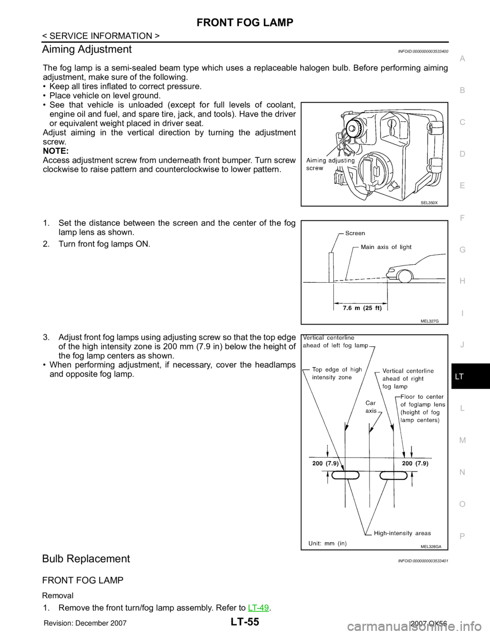
The fog lamp is a semi-sealed beam type which uses a replaceable halogen bulb. Before performing aiming
adjustment, make sure of the following.
• Keep all tires inflated to correct pressure.
• Place vehicle on level ground.
• See that vehicle is unloaded (except for full levels of coolant,
engine oil and fuel, and spare tire, jack, and tools). Have the driver
or equivalent weight placed in driver seat.
Adjust aiming in the vertical direction by turning the adjustment
screw.
NOTE:
Access adjustment screw from underneath front bumper. Turn screw
clockwise to raise pattern and counterclockwise to lower pattern.
1. Set the distance between the screen and the center of the fog
lamp lens as shown.
2. Turn front fog lamps ON.
3. Adjust front fog lamps using adjusting screw so that the top edge
of the high intensity zone is 200 mm (7.9 in) below the height of
the fog lamp centers as shown.
• When performing adjustment, if necessary, cover the headlamps
and opposite fog lamp.
Bulb ReplacementINFOID:0000000003533401
FRONT FOG LAMP
Removal
1. Remove the front turn/fog lamp assembly. Refer to LT- 4 9.
SEL350X
MEL327G
MEL328GA
Page 2552 of 3061
RF-20
< SERVICE INFORMATION >
SUNROOF
Fitting Adjustment
INFOID:0000000003533112
GAP ADJUSTMENT
NOTE:
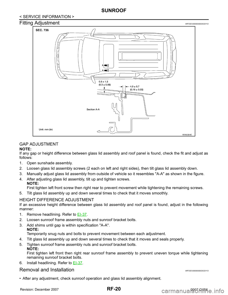
If any gap or height difference between glass lid assembly and roof panel is found, check the fit and adjust as
follows:
1. Open sunshade assembly.
2. Loosen glass lid assembly screws (2 each on left and right sides), then tilt glass lid assembly down.
3. Manually adjust glass lid assembly from outside of vehicle so it resembles "A-A" as shown in the figure.
4. After adjusting glass lid assembly, tilt up and tighten screws.
NOTE:
First tighten left front screw then right rear to prevent movement while tightening the remaining screws.
5. Tilt glass lid assembly up and down several times to check that it moves smoothly.
HEIGHT DIFFERENCE ADJUSTMENT
If an excessive height difference between glass lid assembly and roof panel is found, adjust in the following
manner:
1. Remove headlining. Refer to EI-37
.
2. Loosen sunroof frame assembly nuts and sunroof bracket bolts.
3. Add shims until gap is within specification "A-A".
NOTE:
Temporarily snug nuts and bolts to prevent movement between each adjustment.
4. Tilt glass lid assembly up and down several times to check that it moves and seals properly.
5. Tighten sunroof frame assembly nuts and sunroof bracket bolts.
NOTE:
First tighten left front then right rear sunroof frame assembly to prevent uneven torque while tightening
remaining sunroof bracket bolts.
6. Install headlining. Refer to EI-37
.
Removal and InstallationINFOID:0000000003533113
• After any adjustment, check sunroof operation and glass lid assembly alignment.
WIIA0304E