2007 INFINITI QX56 height adjustment
[x] Cancel search: height adjustmentPage 2554 of 3061
RF-22
< SERVICE INFORMATION >
SUNROOF
SUNROOF UNIT
Removal
CAUTION:
• Always work with a helper.
• When taking sunroof unit out, use shop cloths to protect the seats and trim from damage.
• After installing the sunroof unit and glass lid assembly, check gap adjustment to make sure there is
no malfunction.
1. Remove headlining. Refer to EI-37
.
2. Remove the sunroof glass lid assembly. Refer to "GLASS LID ASSEMBLY".
3. Remove overhead console bracket.
4. Disconnect front and rear drain hoses.
5. Remove front sunroof frame assembly bolts.
6. Remove rear sunroof bracket bolts.
7. Remove the sunroof frame assembly side bolts, then the sunroof unit.
Installation
1. Position the sunroof frame assembly and install the side bolts.
2. Install the sunroof brackets and bolts.
3. Install the front sunroof frame assembly bolts.
4. Connect front and rear drain hoses.
5. Install the overhead console bracket.
6. Install the sunroof glass lid assembly. Refer to "GLASS LID ASSEMBLY".
NOTE:
Adjust sunroof glass lid assembly gap and height, refer to RF-20, "
Fitting Adjustment".
7. Install headlining. Refer to EI-37
.
GLASS LID ASSEMBLY
Removal
1. Open sunshade assembly.
NOTE:
Be sure glass lid assembly is fully closed.
2. Remove side cover LH and RH.
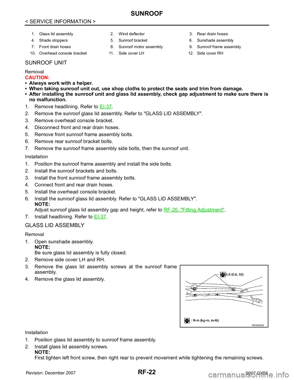
3. Remove the glass lid assembly screws at the sunroof frame
assembly.
4. Remove the glass lid assembly.
Installation
1. Position glass lid assembly to sunroof frame assembly.
2. Install glass lid assembly screws.
NOTE:
First tighten left front screw, then right rear to prevent movement while tightening the remaining screws.
1. Glass lid assembly 2. Wind deflector 3. Rear drain hoses
4. Shade stoppers 5. Sunroof bracket 6. Sunshade assembly
7. Front drain hoses 8. Sunroof motor assembly 9. Sunroof frame assembly
10. Overhead console bracket 11. Side cover LH 12. Side cover RH
WIIA0252E
Page 2575 of 3061
RFD-18
< SERVICE INFORMATION >
REAR FINAL DRIVE ASSEMBLY
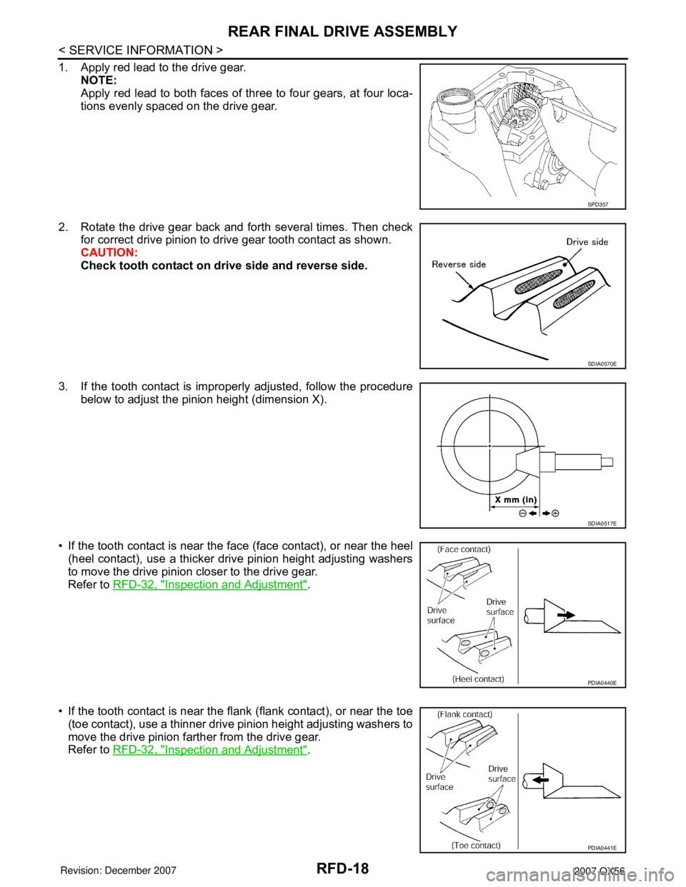
1. Apply red lead to the drive gear.
NOTE:
Apply red lead to both faces of three to four gears, at four loca-
tions evenly spaced on the drive gear.
2. Rotate the drive gear back and forth several times. Then check
for correct drive pinion to drive gear tooth contact as shown.
CAUTION:
Check tooth contact on drive side and reverse side.
3. If the tooth contact is improperly adjusted, follow the procedure
below to adjust the pinion height (dimension X).
• If the tooth contact is near the face (face contact), or near the heel
(heel contact), use a thicker drive pinion height adjusting washers
to move the drive pinion closer to the drive gear.
Refer to RFD-32, "
Inspection and Adjustment".
• If the tooth contact is near the flank (flank contact), or near the toe
(toe contact), use a thinner drive pinion height adjusting washers to
move the drive pinion farther from the drive gear.
Refer to RFD-32, "
Inspection and Adjustment".
SPD357
SDIA0570E
SDIA0517E
PDIA0440E
PDIA0441E
Page 2583 of 3061
RFD-26
< SERVICE INFORMATION >
REAR FINAL DRIVE ASSEMBLY
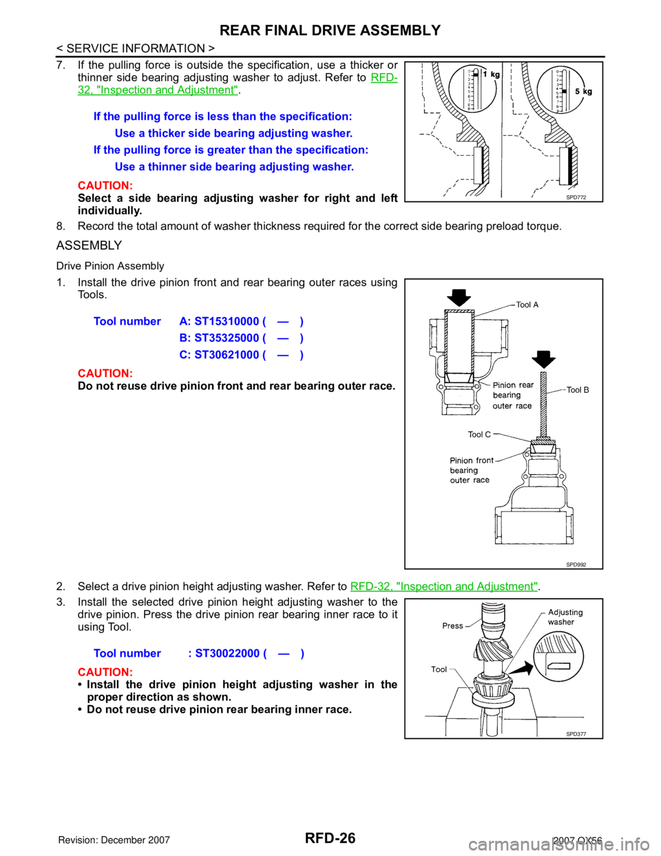
7. If the pulling force is outside the specification, use a thicker or
thinner side bearing adjusting washer to adjust. Refer to RFD-
32, "Inspection and Adjustment".
CAUTION:
Select a side bearing adjusting washer for right and left
individually.
8. Record the total amount of washer thickness required for the correct side bearing preload torque.
ASSEMBLY
Drive Pinion Assembly
1. Install the drive pinion front and rear bearing outer races using
Tools.
CAUTION:
Do not reuse drive pinion front and rear bearing outer race.
2. Select a drive pinion height adjusting washer. Refer to RFD-32, "
Inspection and Adjustment".
3. Install the selected drive pinion height adjusting washer to the
drive pinion. Press the drive pinion rear bearing inner race to it
using Tool.
CAUTION:
• Install the drive pinion height adjusting washer in the
proper direction as shown.
• Do not reuse drive pinion rear bearing inner race.If the pulling force is less than the specification:
Use a thicker side bearing adjusting washer.
If the pulling force is greater than the specification:
Use a thinner side bearing adjusting washer.
SPD772
Tool number A: ST15310000 ( — )
B: ST35325000 ( — )
C: ST30621000 ( — )
SPD992
Tool number : ST30022000 ( — )
SPD377
Page 2601 of 3061
TROUBLE DIAGNOSIS
RSU-11
< SERVICE INFORMATION >
C
D
F
G
H
I
J
K
L
MA
B
RSU
N
O
P
POWER SYSTEM TERMINAL LOOSENESS AND BATTERY INSPECTION
Make sure the battery positive cable, negative cable and ground connection are not loose. In addition, make
sure the battery is sufficiently charged.
CK SUSP INDICATOR LAMP INSPECTION
1. Make sure the CK SUSP indicator lamp turns on for approximately 2 seconds when the ignition switch is
turned ON. If it does not, check the combination meter. Refer to DI-5
.
2. Make sure the lamp turns off approximately 2 seconds after the ignition switch is turned ON. If the lamp
does not turn off, conduct self-diagnosis of the suspension control unit.
3. After conducting the self-diagnosis, be sure to erase the error memory. Refer to RSU-11, "
CONSULT-II
Function (AIR LEVELIZER)" .
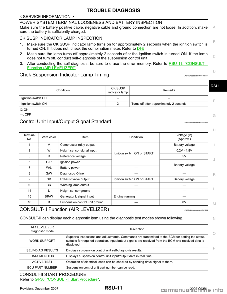
Chek Suspension Indicator Lamp TimingINFOID:0000000003532661
X: ON
—: OFF
Control Unit Input/Output Signal StandardINFOID:0000000003532662
CONSULT-II Function (AIR LEVELIZER)INFOID:0000000003532663
CONSULT-II can display each diagnostic item using the diagnostic test modes shown following.
CONSULT-II START PROCEDURE
Refer to GI-36, "CONSULT-II Start Procedure".
ConditionCK SUSP
indicator lampRemarks
Ignition switch OFF – –
Ignition switch ON X Turns off after approximately 2 seconds.
Te r m i n a l
No.Wire color Item ConditionVoltage (V)
(Approx.)
1 V Compressor relay output
Ignition switch ON or STARTBattery voltage
3 W Height sensor signal input 0.2V - 4.8V
5 R Reference voltage 5V
6 G/R Ignition power
Battery voltage
7W/LBattery power —
8 G/W Diagnostic K-line — —
9 SB Exhaust valve output Ignition switch ON or START Battery voltage
10 BR Warning lamp output — —
14 L Height sensor ground — —
15 BR/W Generator L signal input Engine running —
16 B Suspension control unit ground — 0V
AIR LEVELIZER
diagnostic modeDescription
WORK SUPPORTSupports inspections and adjustments. Commands are transmitted to the BCM for setting the status
suitable for required operation, input/output signals are received from the BCM and received data is
displayed.
SELF-DIAG RESULTS Displays suspension control unit self-diagnosis results.
DATA MONITOR Displays suspension control unit input/output data in real time.
ACTIVE TEST Operation of electrical loads can be checked by sending drive signal to them.
ECU PART NUMBER Suspension control unit part number can be read.
Page 2613 of 3061
REAR SUSPENSION ASSEMBLY
RSU-23
< SERVICE INFORMATION >
C
D
F
G
H
I
J
K
L
MA
B
RSU
N
O
P
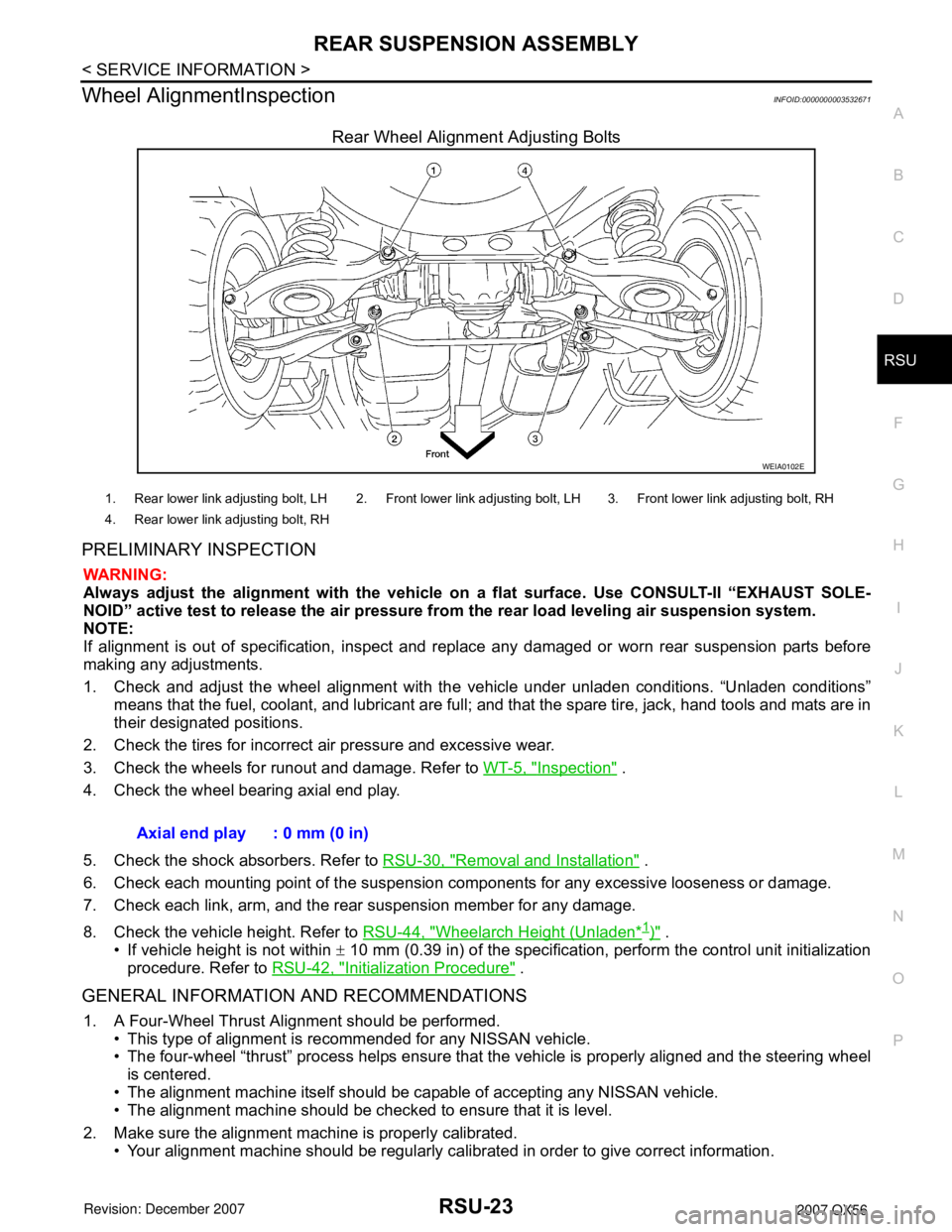
Wheel AlignmentInspectionINFOID:0000000003532671
Rear Wheel Alignment Adjusting Bolts
PRELIMINARY INSPECTION
WARNING:
Always adjust the alignment with the vehicle on a flat surface. Use CONSULT-II “EXHAUST SOLE-
NOID” active test to release the air pressure from the rear load leveling air suspension system.
NOTE:
If alignment is out of specification, inspect and replace any damaged or worn rear suspension parts before
making any adjustments.
1. Check and adjust the wheel alignment with the vehicle under unladen conditions. “Unladen conditions”
means that the fuel, coolant, and lubricant are full; and that the spare tire, jack, hand tools and mats are in
their designated positions.
2. Check the tires for incorrect air pressure and excessive wear.
3. Check the wheels for runout and damage. Refer to WT-5, "
Inspection" .
4. Check the wheel bearing axial end play.
5. Check the shock absorbers. Refer to RSU-30, "
Removal and Installation" .
6. Check each mounting point of the suspension components for any excessive looseness or damage.
7. Check each link, arm, and the rear suspension member for any damage.
8. Check the vehicle height. Refer to RSU-44, "
Wheelarch Height (Unladen*1)" .
• If vehicle height is not within ± 10 mm (0.39 in) of the specification, perform the control unit initialization
procedure. Refer to RSU-42, "
Initialization Procedure" .
GENERAL INFORMATION AND RECOMMENDATIONS
1. A Four-Wheel Thrust Alignment should be performed.
• This type of alignment is recommended for any NISSAN vehicle.
• The four-wheel “thrust” process helps ensure that the vehicle is properly aligned and the steering wheel
is centered.
• The alignment machine itself should be capable of accepting any NISSAN vehicle.
• The alignment machine should be checked to ensure that it is level.
2. Make sure the alignment machine is properly calibrated.
• Your alignment machine should be regularly calibrated in order to give correct information.
WEIA0102E
1. Rear lower link adjusting bolt, LH 2. Front lower link adjusting bolt, LH 3. Front lower link adjusting bolt, RH
4. Rear lower link adjusting bolt, RH
Axial end play : 0 mm (0 in)