2007 INFINITI QX56 oil pressure
[x] Cancel search: oil pressurePage 2512 of 3061
POWER STEERING OIL PUMP
PS-21
< SERVICE INFORMATION >
C
D
E
F
H
I
J
K
L
MA
B
PS
N
O
P
POWER STEERING OIL PUMP
On-Vehicle Inspection and ServiceINFOID:0000000003532831
CHECKING RELIEF OIL PRESSURE
CAUTION:
Before starting work, confirm belt tension is proper.
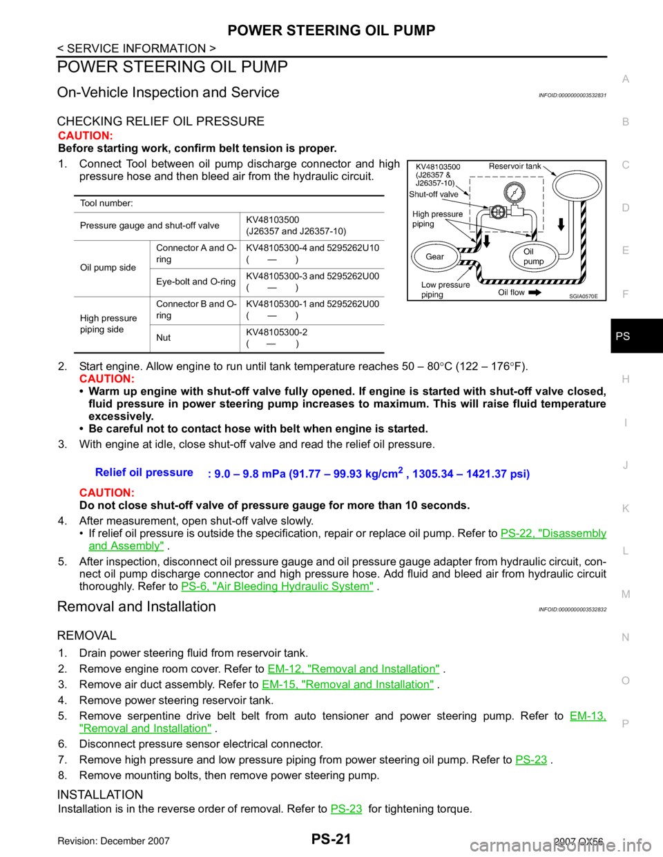
1. Connect Tool between oil pump discharge connector and high
pressure hose and then bleed air from the hydraulic circuit.
2. Start engine. Allow engine to run until tank temperature reaches 50 – 80°C (122 – 176°F).
CAUTION:
• Warm up engine with shut-off valve fully opened. If engine is started with shut-off valve closed,
fluid pressure in power steering pump increases to maximum. This will raise fluid temperature
excessively.
• Be careful not to contact hose with belt when engine is started.
3. With engine at idle, close shut-off valve and read the relief oil pressure.
CAUTION:
Do not close shut-off valve of pressure gauge for more than 10 seconds.
4. After measurement, open shut-off valve slowly.
• If relief oil pressure is outside the specification, repair or replace oil pump. Refer to PS-22, "
Disassembly
and Assembly" .
5. After inspection, disconnect oil pressure gauge and oil pressure gauge adapter from hydraulic circuit, con-
nect oil pump discharge connector and high pressure hose. Add fluid and bleed air from hydraulic circuit
thoroughly. Refer to PS-6, "
Air Bleeding Hydraulic System" .
Removal and InstallationINFOID:0000000003532832
REMOVAL
1. Drain power steering fluid from reservoir tank.
2. Remove engine room cover. Refer to EM-12, "
Removal and Installation" .
3. Remove air duct assembly. Refer to EM-15, "
Removal and Installation" .
4. Remove power steering reservoir tank.
5. Remove serpentine drive belt belt from auto tensioner and power steering pump. Refer to EM-13,
"Removal and Installation" .
6. Disconnect pressure sensor electrical connector.
7. Remove high pressure and low pressure piping from power steering oil pump. Refer to PS-23
.
8. Remove mounting bolts, then remove power steering pump.
INSTALLATION
Installation is in the reverse order of removal. Refer to PS-23 for tightening torque.
Tool number:
Pressure gauge and shut-off valveKV48103500
(J26357 and J26357-10)
Oil pump sideConnector A and O-
ringKV48105300-4 and 5295262U10
(—)
Eye-bolt and O-ringKV48105300-3 and 5295262U00
(—)
High pressure
piping sideConnector B and O-
ringKV48105300-1 and 5295262U00
(—)
NutKV48105300-2
( — )
SGIA0570E
Relief oil pressure
: 9.0 – 9.8 mPa (91.77 – 99.93 kg/cm2 , 1305.34 – 1421.37 psi)
Page 2513 of 3061
PS-22
< SERVICE INFORMATION >
POWER STEERING OIL PUMP
• After installation, bleed air. Refer to PS-6, "Air Bleeding Hydraulic System" .
NOTE:
Belt tension is automatic and requires no adjustment.
Disassembly and AssemblyINFOID:0000000003532833
INSPECTION BEFORE DISASSEMBLY
Disassemble the power steering oil pump only if the following items are found.
• Deformed or damaged pulley, bracket, connector or suction pipe.
• Oil leakage from the suction pipe or connector.
DISASSEMBLY
NOTE:
Mount the power steering oil pump in a vise as needed.
1. Remove the connector bolt, connector and copper washers.
CAUTION:
Do not reuse the copper washers.
2. Remove the suction pipe and O-ring.
CAUTION:
Do not reuse the O-ring.
3. Remove the pulley nut and pulley.
4. Remove the bracket bolts and bracket.
INSPECTION AFTER DISASSEMBLY
Body Assembly Inspection
Check the power steering oil pump body assembly for damage. If any damage is found, replace with a new
power steering oil pump assembly.
ASSEMBLY
Assembly is in the reverse order of disassembly.
CAUTION:
• Do not reuse the copper gaskets
• Do not reuse the O-ring. Apply a coat of Genuine Nissan PSF or equivalent to the O-ring.
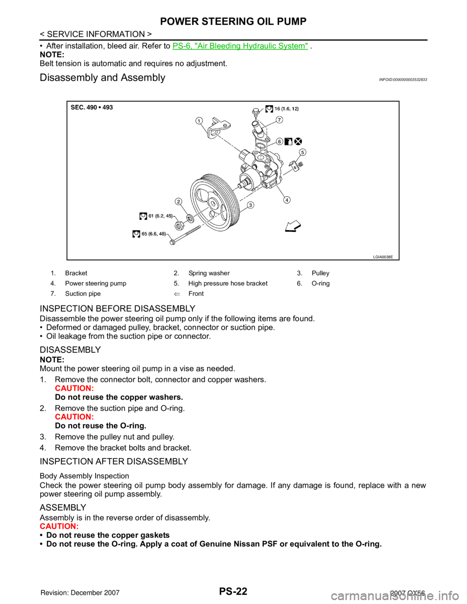
1. Bracket 2. Spring washer 3. Pulley
4. Power steering pump 5. High pressure hose bracket 6. O-ring
7. Suction pipe⇐Front
LGIA0038E
Page 2514 of 3061
HYDRAULIC LINE
PS-23
< SERVICE INFORMATION >
C
D
E
F
H
I
J
K
L
MA
B
PS
N
O
P
HYDRAULIC LINE
Removal and InstallationINFOID:0000000003532834
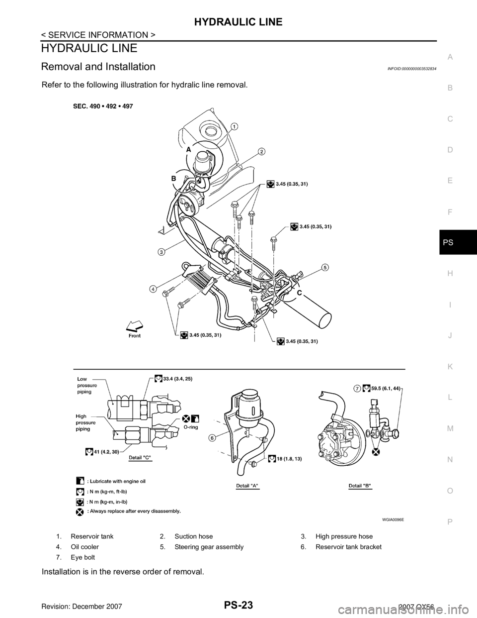
Refer to the following illustration for hydralic line removal.
Installation is in the reverse order of removal.
1. Reservoir tank 2. Suction hose 3. High pressure hose
4. Oil cooler 5. Steering gear assembly 6. Reservoir tank bracket
7. Eye bolt
WGIA0096E
Page 2518 of 3061

SERVICE DATA AND SPECIFICATIONS (SDS)
PS-27
< SERVICE INFORMATION >
C
D
E
F
H
I
J
K
L
MA
B
PS
N
O
P
Oil PumpINFOID:0000000003532839
Steering FluidINFOID:0000000003532840
Rack sliding forceAt the neutral point:
Range within ± 11.5 mm
(±0.453 in) from the neutral
position
(in power ON)Area average value 147 − 211 N (14.99 − 21.52 kg, 33.1 − 47.52 lb)
Allowable variation 98 N (10 kg, 22 lb) or less
Whole area (in power OFF)Peak value 294 N (30.0 kg, 66 lb) or less
Allowable variation 147 N (16 kg, 35 lb) or less Steering gear modelPR26AM
Relief oil pressure
9.0 − 9.8 mPa (91.77 − 99.93 kg/cm2, 1305.34 − 1421.37 psi)
Fluid capacity
Approx. 1.0 (1-1/8 US qt, 7/8 Imp qt)
Page 2617 of 3061
REAR SUSPENSION MEMBER
RSU-27
< SERVICE INFORMATION >
C
D
F
G
H
I
J
K
L
MA
B
RSU
N
O
P
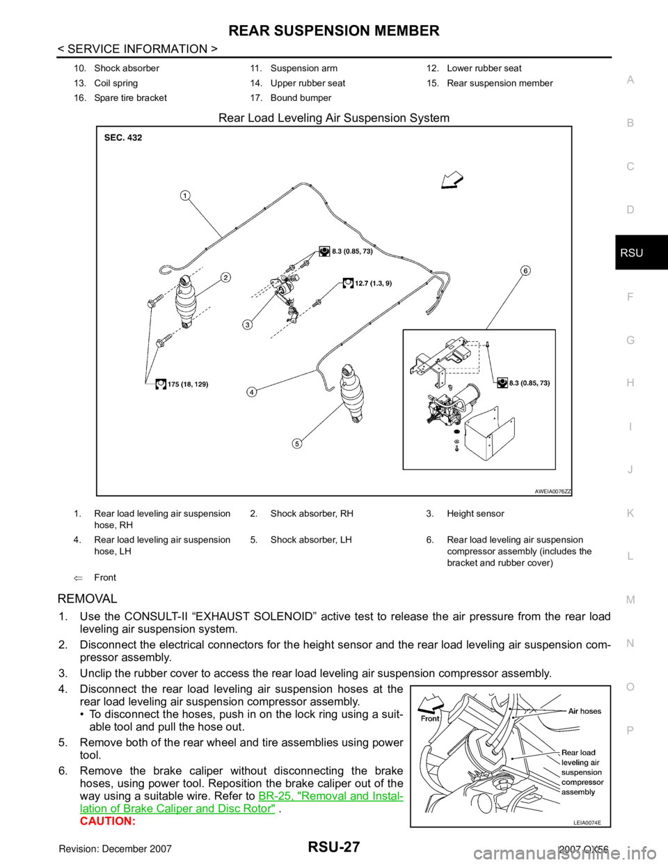
Rear Load Leveling Air Suspension System
REMOVAL
1. Use the CONSULT-II “EXHAUST SOLENOID” active test to release the air pressure from the rear load
leveling air suspension system.
2. Disconnect the electrical connectors for the height sensor and the rear load leveling air suspension com-
pressor assembly.
3. Unclip the rubber cover to access the rear load leveling air suspension compressor assembly.
4. Disconnect the rear load leveling air suspension hoses at the
rear load leveling air suspension compressor assembly.
• To disconnect the hoses, push in on the lock ring using a suit-
able tool and pull the hose out.
5. Remove both of the rear wheel and tire assemblies using power
tool.
6. Remove the brake caliper without disconnecting the brake
hoses, using power tool. Reposition the brake caliper out of the
way using a suitable wire. Refer to BR-25, "
Removal and Instal-
lation of Brake Caliper and Disc Rotor" .
CAUTION:
10. Shock absorber 11. Suspension arm 12. Lower rubber seat
13. Coil spring 14. Upper rubber seat 15. Rear suspension member
16. Spare tire bracket 17. Bound bumper
AWEIA0076ZZ
1. Rear load leveling air suspension
hose, RH2. Shock absorber, RH 3. Height sensor
4. Rear load leveling air suspension
hose, LH5. Shock absorber, LH 6. Rear load leveling air suspension
compressor assembly (includes the
bracket and rubber cover)
⇐Front
LEIA0074E
Page 2625 of 3061
REAR LOWER LINK & COIL SPRING
RSU-35
< SERVICE INFORMATION >
C
D
F
G
H
I
J
K
L
MA
B
RSU
N
O
P
REAR LOWER LINK & COIL SPRING
Removal and InstallationINFOID:0000000003532676
REMOVAL
1. Remove the wheel and tire assembly using power tool. Refer to WT-7, "Rotation" .
2. Use CONSULT-II "EXHAUST SOLENOID" active test to release the air pressure from the rear load level-
ing air suspension system.
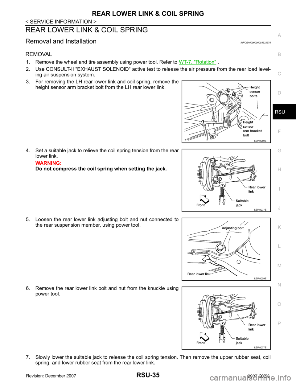
3. For removing the LH rear lower link and coil spring, remove the
height sensor arm bracket bolt from the LH rear lower link.
4. Set a suitable jack to relieve the coil spring tension from the rear
lower link.
WARNING:
Do not compress the coil spring when setting the jack.
5. Loosen the rear lower link adjusting bolt and nut connected to
the rear suspension member, using power tool.
6. Remove the rear lower link bolt and nut from the knuckle using
power tool.
7. Slowly lower the suitable jack to release the coil spring tension. Then remove the upper rubber seat, coil
spring, and lower rubber seat from the rear lower link.
LEIA0080E
LEIA0077E
LEIA0009E
LEIA0077E
Page 2838 of 3061
TF-16
< SERVICE INFORMATION >
ALL-MODE 4WD SYSTEM
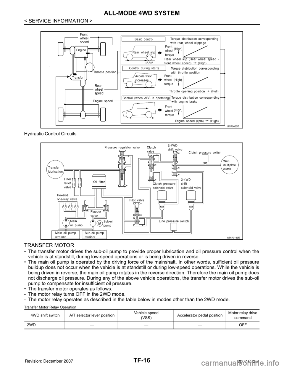
Hydraulic Control Circuits
TRANSFER MOTOR
• The transfer motor drives the sub-oil pump to provide proper lubrication and oil pressure control when the
vehicle is at standstill, during low-speed operations or is being driven in reverse.
• The main oil pump is operated by the driving force of the mainshaft. In other words, sufficient oil pressure
buildup does not occur when the vehicle is at standstill or during low-speed operations. While the vehicle is
being driven in reverse, the main oil pump rotates in the reverse direction. Therefore the main oil pump does
not discharge oil pressure. During any of the above vehicle operations, the transfer motor drives the sub-oil
pump to compensate for insufficient oil pressure.
• The transfer motor operates as follows.
- The motor relay turns OFF in the 2WD mode.
- The motor relay operates as described in the table below in modes other than the 2WD mode.
Transfer Motor Relay Operation
LDIA0055E
WDIA0163E
4WD shift switch A/T selector lever positionVehicle speed
(VSS)Accelerator pedal positionMotor relay drive
command
2WD — — — OFF
Page 2839 of 3061

ALL-MODE 4WD SYSTEM
TF-17
< SERVICE INFORMATION >
C
E
F
G
H
I
J
K
L
MA
B
TF
N
O
P
*: After 2.5 seconds have elapsed.
• 4WD shift switch, PNP switch, Neutral-4LO switch, vehicle speed sensor and throttle position sensor are
used in conjunction with the transfer motor.
WAIT DETECTION SWITCH
• The wait detection switch operates when there is “circulating” torque produced in the propeller shaft (L→H)
or when there is a phase difference between 2-4 sleeve and clutch drum (H→L). After the release of the “cir-
culating” torque, the wait detection switch helps provide the 4WD lock gear (clutch drum) shifts. A difference
may occur between the operation of the 4WD shift switch and actual drive mode. At this point, the wait
detection switch senses an actual drive mode.
• The wait detection switch operates as follows.
- 4WD lock gear (clutch drum) locked: ON
- 4WD lock gear (clutch drum) released: OFF
• The wait detection switch senses an actual drive mode and the 4WD shift indicator lamp indicates the vehi-
cle drive mode.
NEUTRAL-4LO SWITCH
The neutral-4LO switch detects that transfer gear is in neutral or 4LO (or shifting from neutral to 4LO) condi-
tion by L-H shift fork position.
AT P S W I T C H
ATP switch detects if transfer gear is in a neutral condition by L-H shift fork position.
NOTE:
Transfer gear may be in a neutral condition in 4H-4LO.
2-4WD SHIFT SOLENOID VALVE
The 2-4WD shift solenoid valve operates to apply oil pressure to the wet-multiplate clutch, depending on the
drive mode. The driving force is transmitted to the front wheels through the clutch so the vehicle is set in the
4WD mode. Setting the vehicle in the 2WD mode requires no pressure buildup. In other words, pressure force
applied to the wet-multiplate clutch becomes zero.
CLUTCH PRESSURE SOLENOID VALVE
The clutch pressure solenoid valve distributes torque (front and rear) in AUTO mode.
4H (LOCK) and 4LO“N” position 0 — ON
“P” position 00 - 0.07/8 OFF*
0.07/8 - 1/8 HOLD
1/8 - MAX ON
Other than “R” position0 < VSS ≤ 50 km/h (31 MPH)
— ON
50 km/h (31 MPH) < VSS < 55
km/h (34 MPH) HOLD
55 km/h (34 MPH) ≤ VSS OFF
“R” position — — ON
“R” position — — ON
AUTO“P” or “N” position00 - 0.07/8 OFF*
0.07/8 - 1/8 HOLD
1/8 - MAX ON
0 < VSS ≤ 50 km/h (31 MPH)
— ON
50 km/h (31 MPH) < VSS < 55
km/h (34 MPH) HOLD
55 km/h (34 MPH) ≤ VSS OFF
Other than “R”, "P" and "N"
position0 < VSS ≤ 50 km/h (31 MPH)
— ON
50 km/h (31 MPH) < VSS < 55
km/h (34 MPH) HOLD
55 km/h (34 MPH) ≤ VSS OFF 4WD shift switch A/T selector lever positionVehicle speed
(VSS)Accelerator pedal positionMotor relay drive
command