Page 2634 of 3061
RSU-44
< SERVICE INFORMATION >
SERVICE DATA AND SPECIFICATIONS (SDS)
Wheelarch Height (Unladen*
1)INFOID:0000000003532684
Unit: mm (in)
*1: Fuel, engine coolant and engine oil full. Spare tire, jack, hand tools and mats in designated positions.
*2: Verify the vehicle height. If vehicle height is not within ± 10 mm (0.39 in) of the specification, perform the control unit initialization pro-
cedure. Refer to RSU-42, "
Initialization Procedure" . Suspension type
Air leveling*
2
Applied model2WD 4WD
Front wheelarch height (Hf)913
(35.94)931
(36.65)
Rear wheelarch height (Hr)912
(35.91)932
(36.69)
LEIA0085E
Page 2832 of 3061
TF-10
< SERVICE INFORMATION >
NOISE, VIBRATION AND HARSHNESS (NVH) TROUBLESHOOTING
NOISE, VIBRATION AND HARSHNESS (NVH) TROUBLESHOOTING
NVH Troubleshooting ChartINFOID:0000000003532512
Use the chart below to help you find the cause of the symptom. The numbers indicate the order of the inspec-
tion. If necessary, repair or replace these parts.
Reference page
TF-11TF-128TF-128TF-128TF-128
SUSPECTED PARTS
(Possible cause)
TRANSFER FLUID (Level low)
TRANSFER FLUID (Wrong)
TRANSFER FLUID (Level too high)
LIQUID GASKET (Damaged)
O-RING (Worn or damaged)
OIL SEAL (Worn or damaged)
SHIFT FORK (Worn or damaged)
GEAR (Worn or damaged)
BEARING (Worn or damaged)
SymptomNoise 1 2 3 3
Transfer fluid leakage 31222
Hard to shift or will not shift 1 1 2
Page 2939 of 3061
FRONT OIL SEAL
TF-117
< SERVICE INFORMATION >
C
E
F
G
H
I
J
K
L
MA
B
TF
N
O
P
1. Install the new oil seal until it is flush with the end face of the
front case using Tool.
CAUTION:
• Do not reuse oil seal.
• Apply petroleum jelly to oil seal.
2. Align the matching mark of the front drive shaft with the match-
ing mark of the companion flange, then install the companion
flange.
3. Install the new self-lock nut. Tighten to the specified torque
using Tool. Refer to TF-128, "
Disassembly and Assembly".
CAUTION:
Do not reuse self-lock nut.
4. Install the front propeller shaft. Refer to PR-4, "
Removal and
Installation".
5. Refill the transfer with fluid and check fluid level. Refer to TF-11
.
6. Check the transfer for fluid leakage. Refer to TF-11, "
Inspec-
tion". Tool number : KV38100500 ( — )
SDIA2662E
SDIA2658E
Tool number : KV40104000 ( — )
LDIA0147E
Page 2941 of 3061
REAR OIL SEAL
TF-119
< SERVICE INFORMATION >
C
E
F
G
H
I
J
K
L
MA
B
TF
N
O
P
3. Install the new dust cover to the rear case using Tool.
CAUTION:
• Do not reuse dust cover.
• Apply petroleum jelly to dust cover.
4. Install the rear propeller shaft. Refer to PR-8, "
Removal and
Installation".
5. Refill the transfer with fluid and check fluid level. Refer to TF-11,
"Replacement".
6. Check the transfer for fluid leakage. Refer to TF-11, "
Inspec-
tion". Tool number : KV40105310 ( — )
PDIA0116E
Page 2950 of 3061

TF-128
< SERVICE INFORMATION >
TRANSFER ASSEMBLY
TRANSFER ASSEMBLY
Removal and InstallationINFOID:0000000003532570
REMOVAL
1. Remove the drain plug and gasket. Drain the fluid. Refer to TF-11, "Replacement".
2. Remove the A/T undercover using power tool.
3. Remove the center exhaust tube and main muffler. Refer to EX-3, "
Removal and Installation".
4. Remove the front and rear propeller shafts. Refer to PR-4, "
Removal and Installation" (front), PR-8,
"Removal and Installation" (rear).
CAUTION:
Do not damage spline, sleeve yoke and rear oil seal when removing rear propeller shaft.
NOTE:
Insert a plug into the rear oil seal after removing the rear propeller shaft.
5. Remove the A/T nuts from the A/T crossmember.
6. Position two suitable jacks under the A/T and transfer assembly.
7. Remove the crossmember. Refer to AT-223, "
Removal and Installation (2WD)".
WARNING:
Support A/T and transfer assembly using two suitable jacks while removing crossmember.
8. Disconnect the electrical connectors from the following:
•ATP switch
• Neutral 4LO switch
• Wait detection switch
• Transfer motor
• Transfer control device
• Transfer terminal cord assembly
9. Disconnect each air breather hose from the following. Refer to TF-122, "
Removal and Installation".
• Actuator
• Breather tube (transfer)
• Transfer motor (case connector)
10. Remove the transfer control device from the extension housing.
11. Remove the transfer to A/T and A/T to transfer bolts.
WARNING:
Support transfer assembly with suitable jack while removing it.
12. Remove the transfer assembly.
INSTALLATION
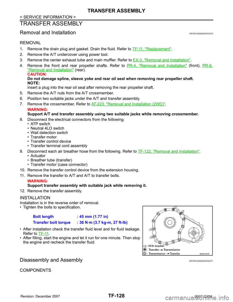
Installation is in the reverse order of removal.
• Tighten the bolts to specification.
• After installation check the transfer fluid level and for fluid leakage.
Refer to TF-11
.
• After filling, start the engine and let it run for one minute. Then stop
the engine and recheck the transfer fluid.
Disassembly and AssemblyINFOID:0000000003532571
COMPONENTS
Bolt length : 45 mm (1.77 in)
Transfer bolt torque : 36 N·m (3.7 kg-m, 27 ft-lb)
SDIA3181E